Week 9 - Challenge 1 - Base Bracket Design
AIM
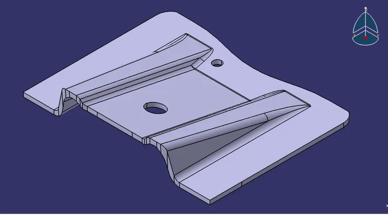
To create the Base Bracket Plastic component through the given Class-A surface.
PROCEDURE
Step 1 : Check the conitivity of the components
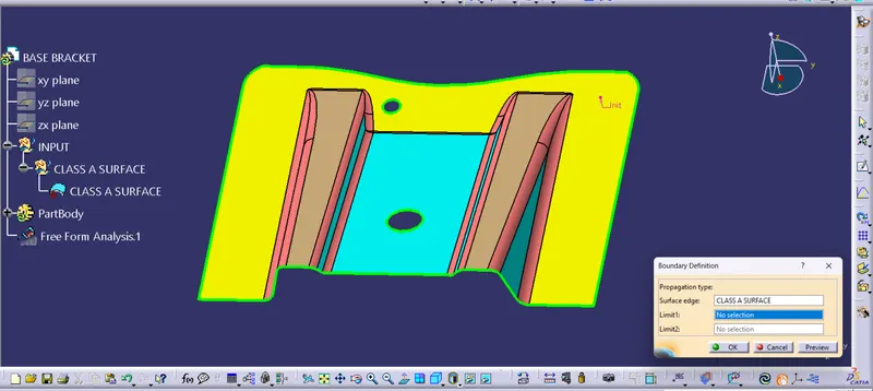
Step 2 : Create dummy tooling axis
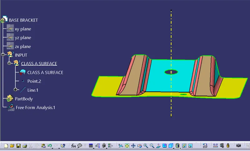
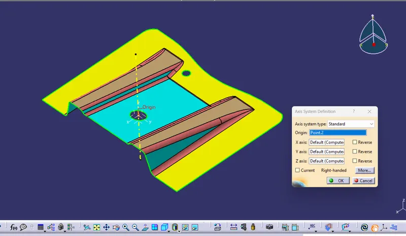
Step 3 : Set the axis system
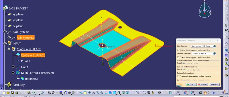
Step 4 : Take the intersect along the y direction and find the surfaces which are inclined to tooling axis.
Step 5 : Create the main tooling axis by bisecting lines.
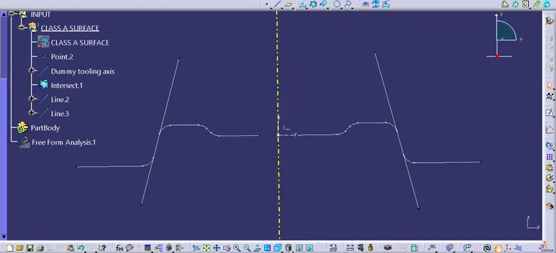
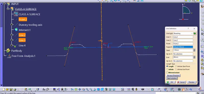
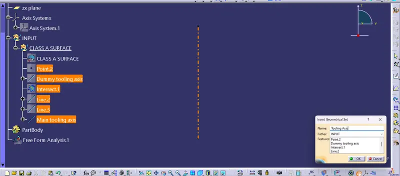
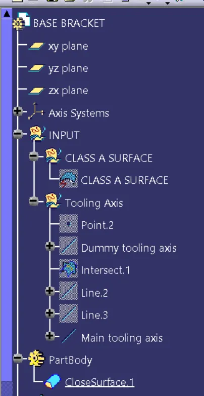
Step 6 : Insert a Geometrical set and put all the axis constructions in it and hide all expect the main tooling axis.
Step 7 : Change to material mode and goto 'Feature Draft Analysis'
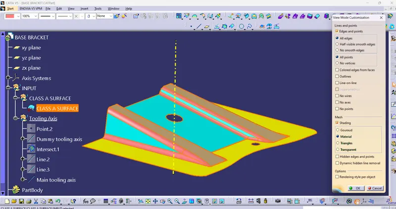
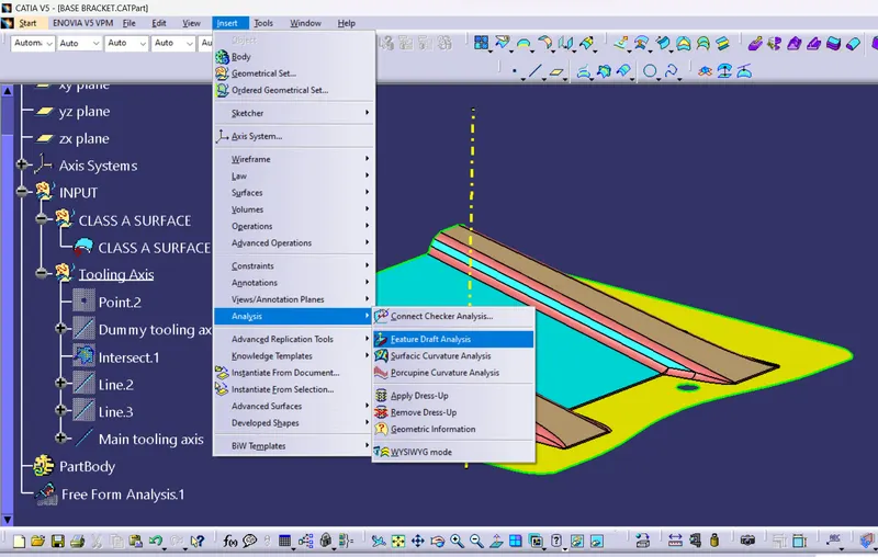
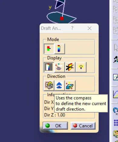
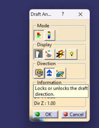
Step 8 : Select the compass in draft analysis to define the new current draft direction. Pick and place the compass on the component.Once compass is placed click on 'Lock draft direction'.
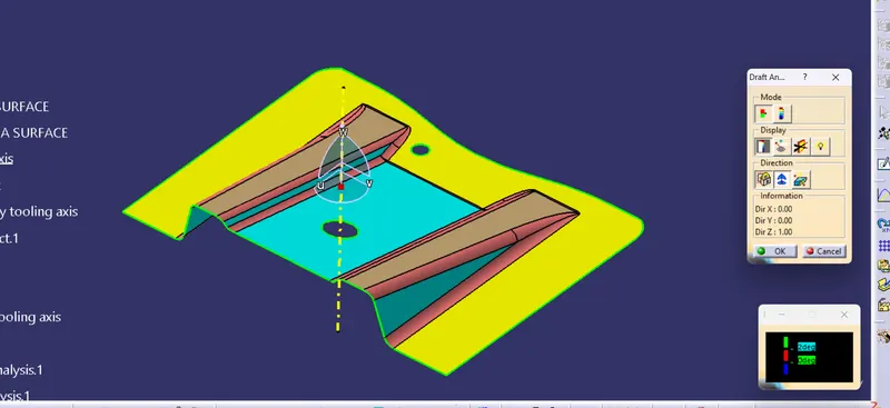
Step 9 : Click on the part body and check the draft. The Green indicated body is equal or above minium given draft angle.
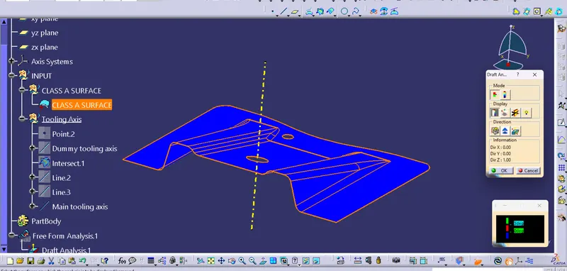
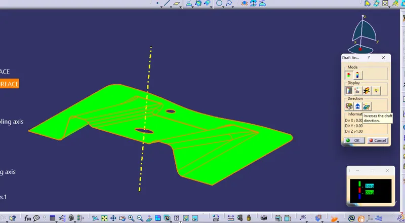
Step 10 : Once the draft anlalysis is done we can proceed to make the core and cavity for the part.For that first insert new geometrical set, Then extract the surfaces witn 'no propogation'
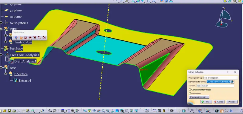
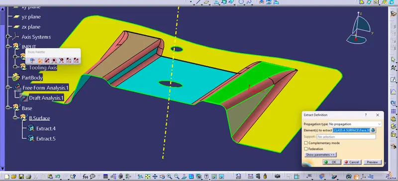
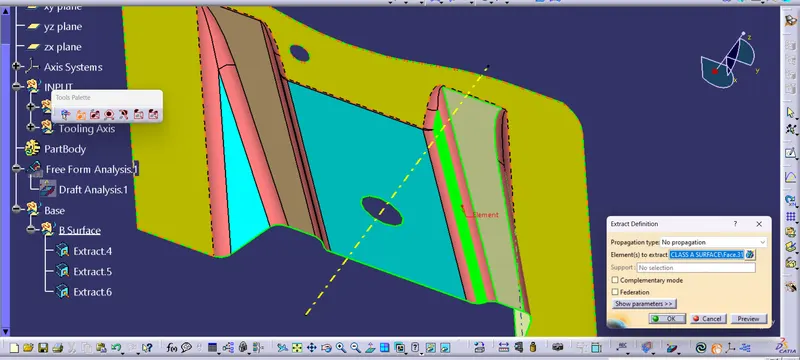
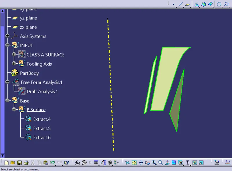
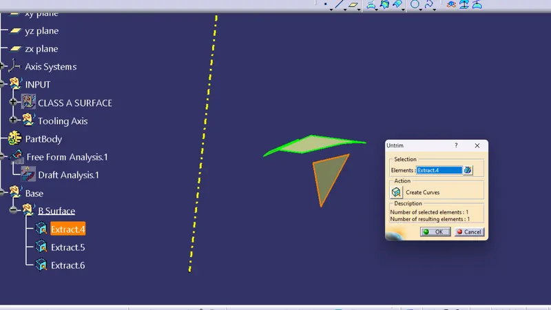
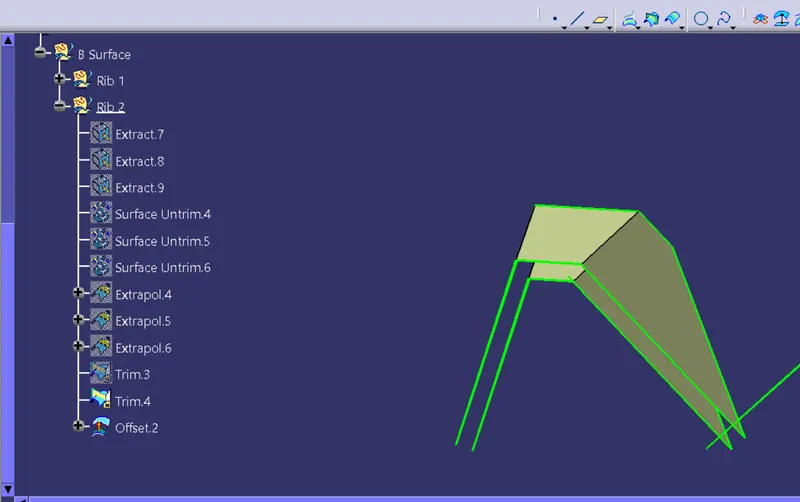
Step 11 : Untrim the faces onebyone.And then using 'Extrapolate' extent the planes for 10 mm
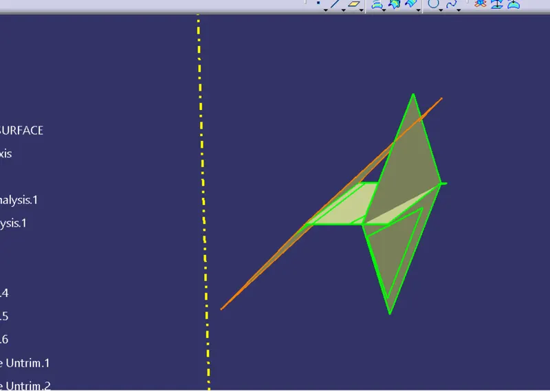
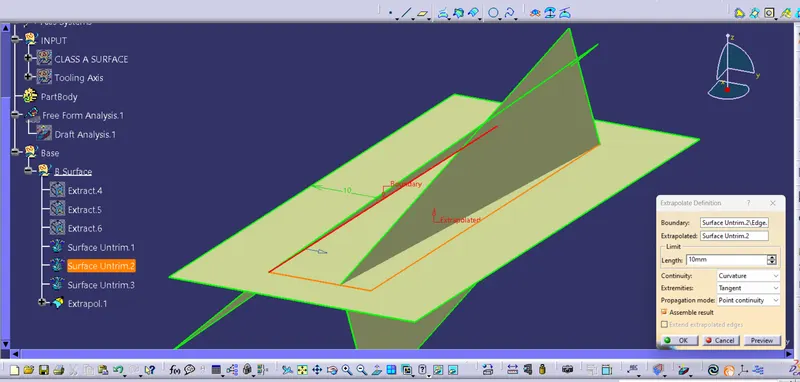
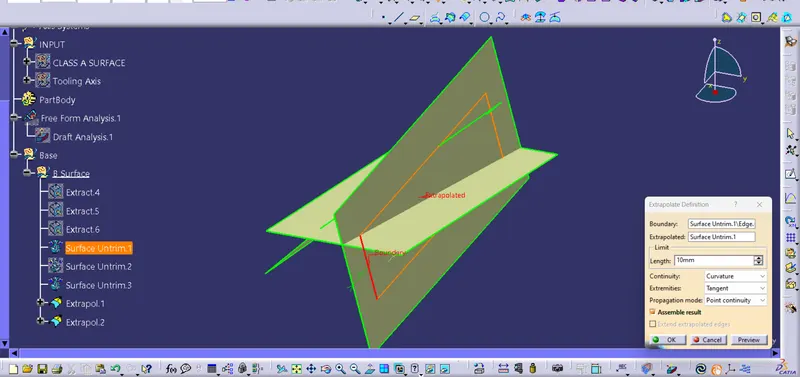
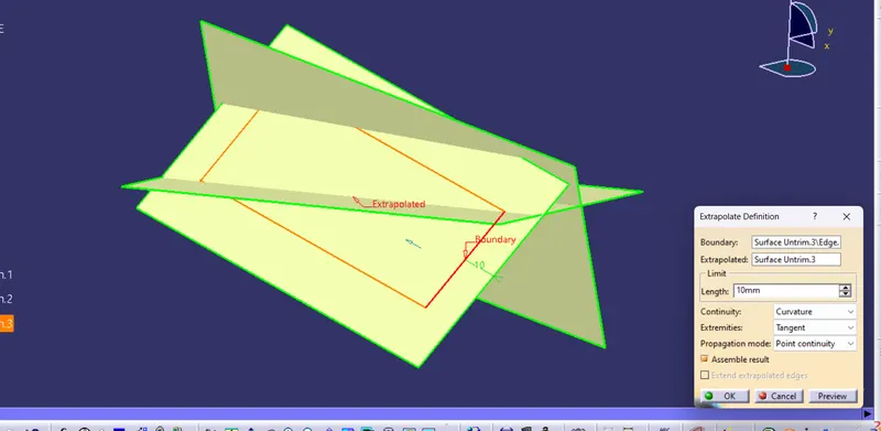
Step 12 : Using Trim command trimout the required component surface
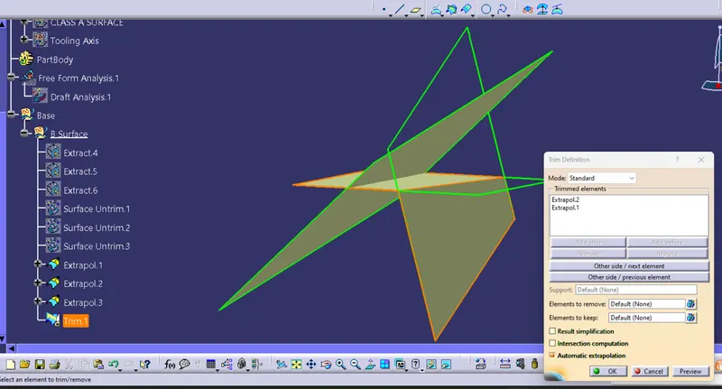
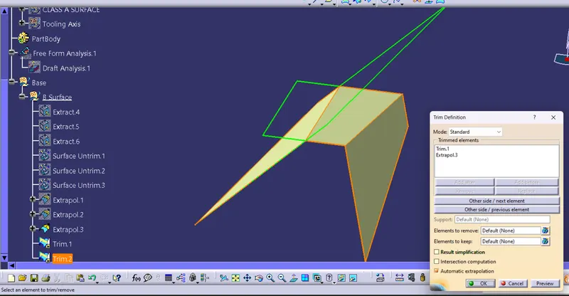
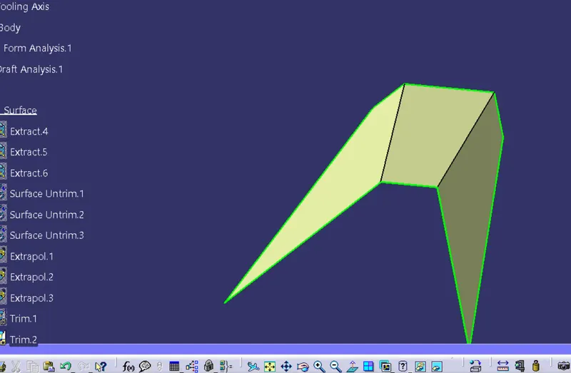
Step 13 : After getting the required surface, using Offset Command offset the surface to the thickness of the component which is 2.5 mm to get the part below ie core.
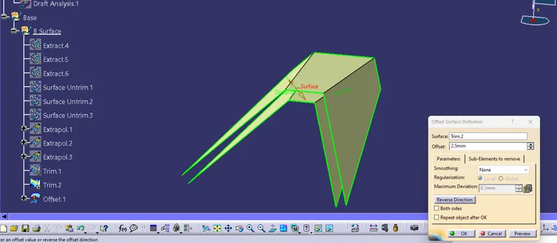
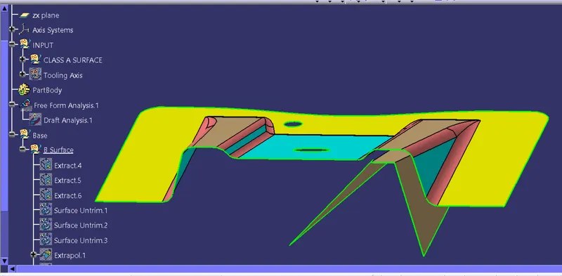
Step 14 : Repeat the steps to get the next Rib part.
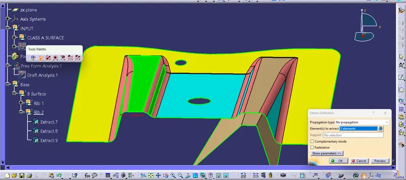
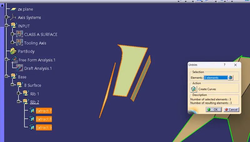
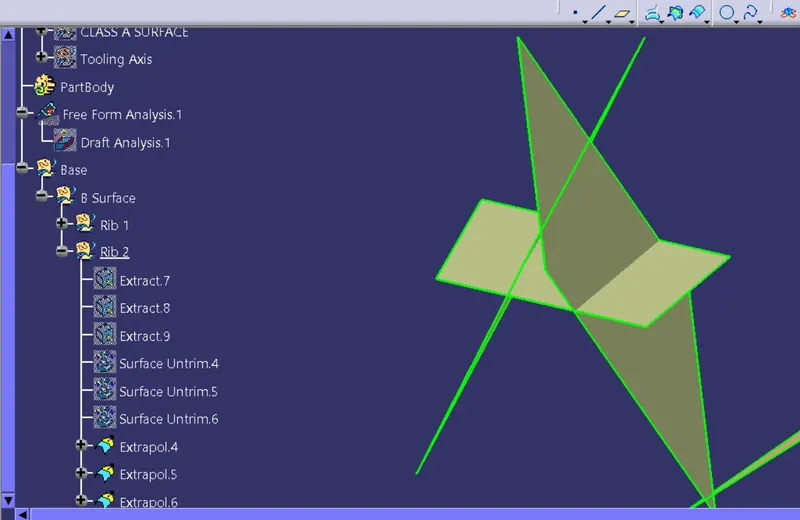
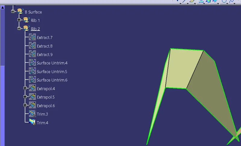
Step 15 : Extrat the other surface which is a base and then untrim the surface and extrapolate it..Then e offset if for 2.5 mm and trim them together.
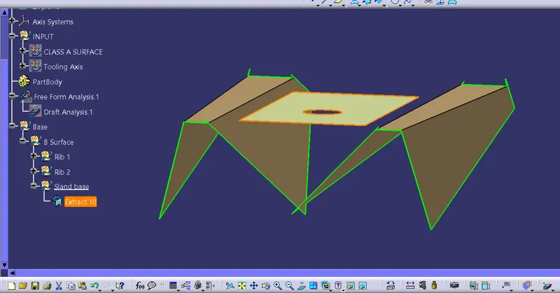
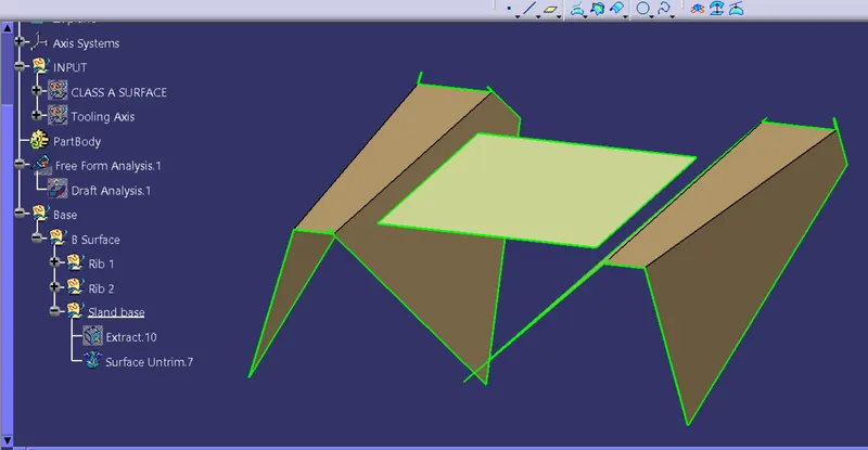
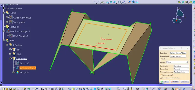
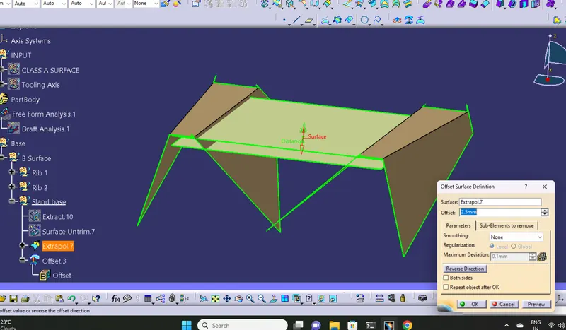
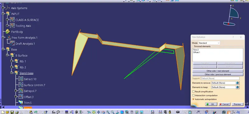
Step 16 : Reperat the steps for the large base.
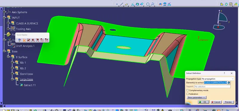
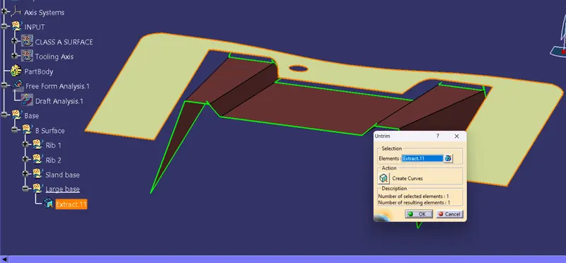
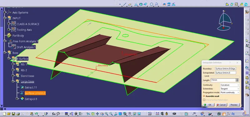
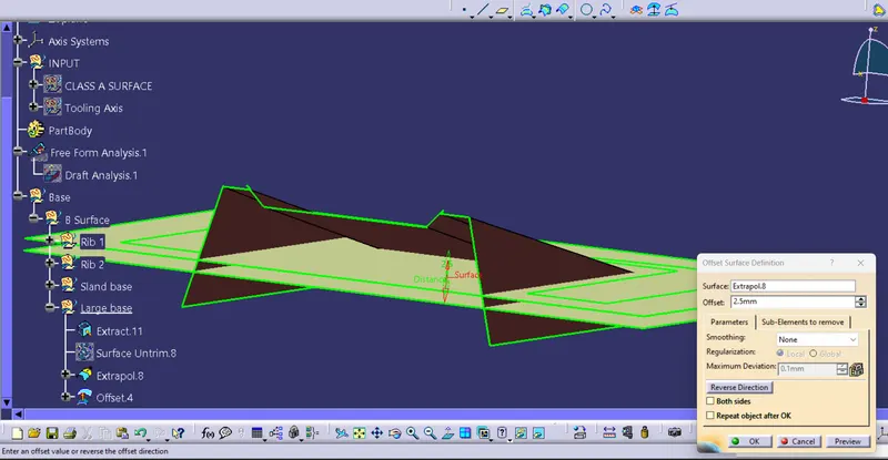
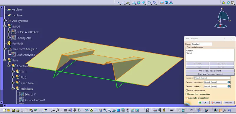
Step 17 : Give fillet using edge fillet, the value of the fillet will be fillet radius + thickness of the component.
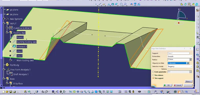
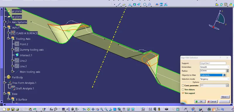
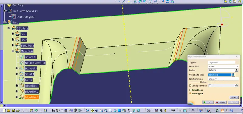
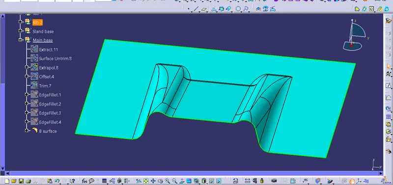
Step 18 : Once the B surface is completed, next create the C Surface. For that insert new geometrical set and pick the outside boundry of the class A surface.
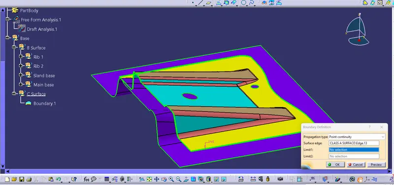
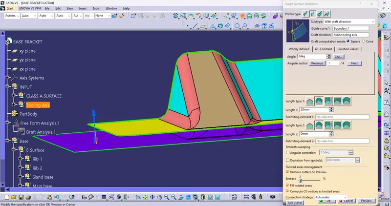
Step 19 : Goto 'Sweep' command to get the surface which closes class A and class B that is the class C surface.
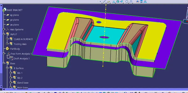
Step 20 : Similarly we have to make the holes in the surface
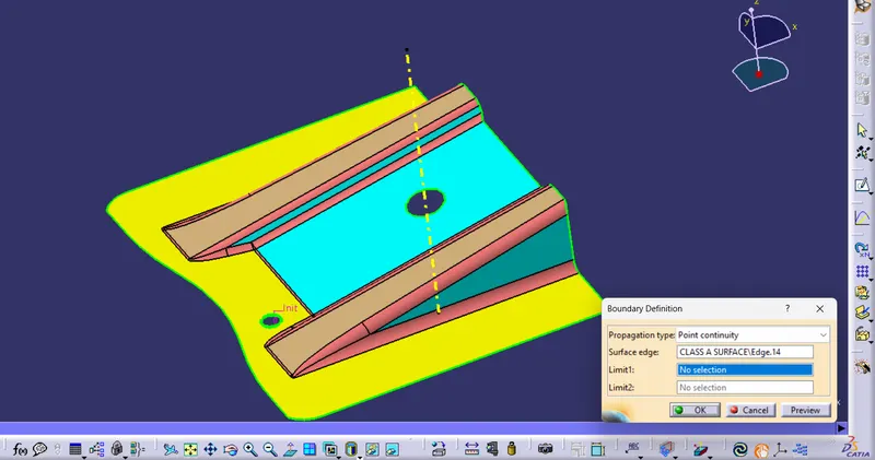
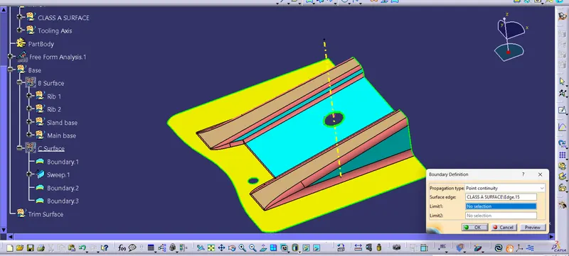
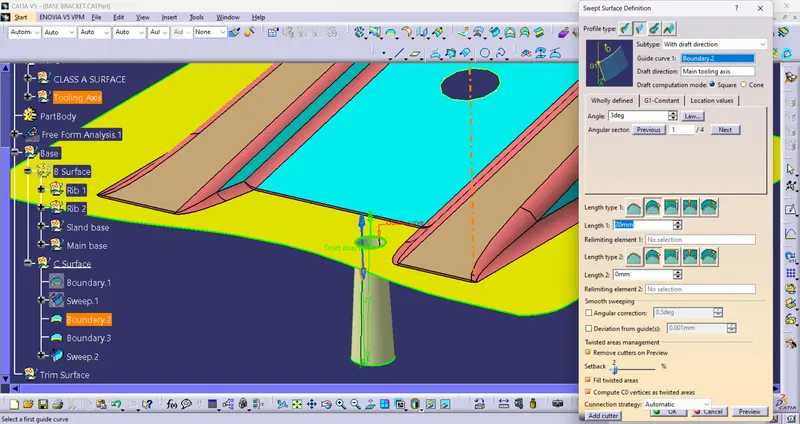
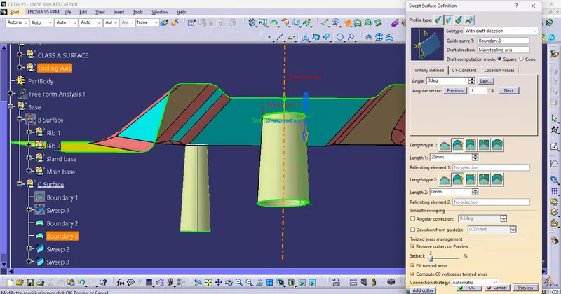
Step 20 : Join C and A surface together using 'Join' Command.
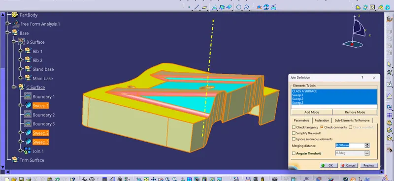
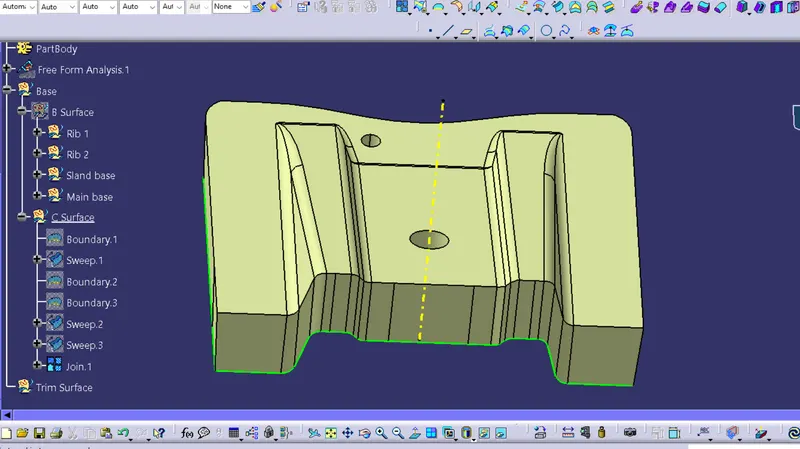
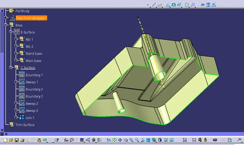
Step 21 : Using the B surface created, trim off the C surface to get the closed surface.
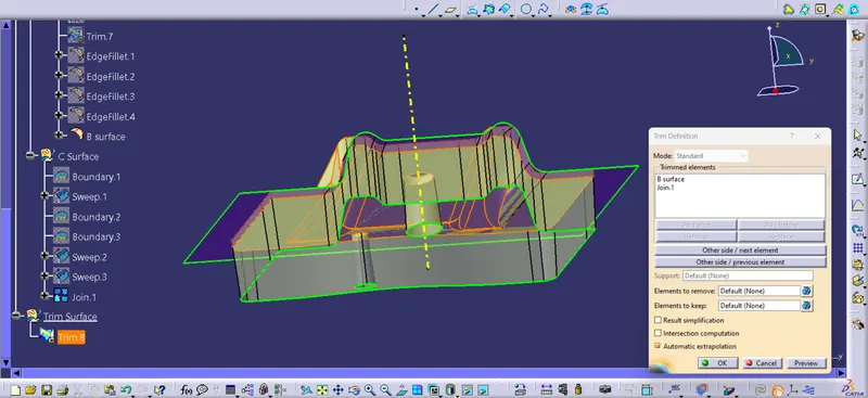
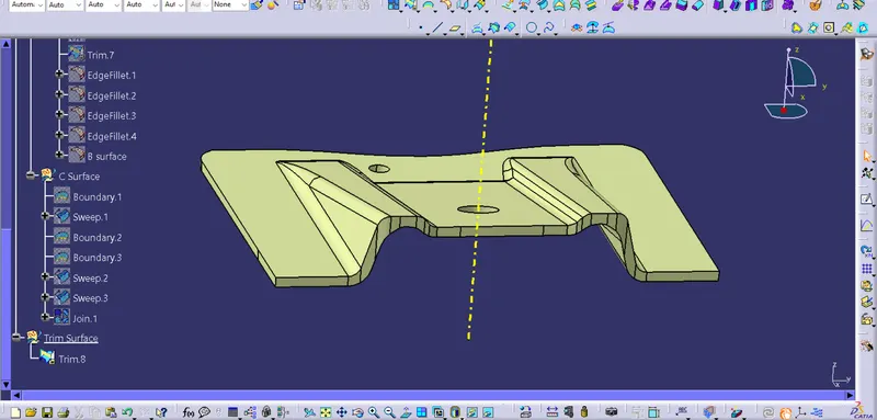
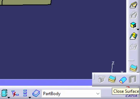
Step 22 : Now switch to 'Part Design' workbench and using 'Close Surface' command make the surface into solid body.
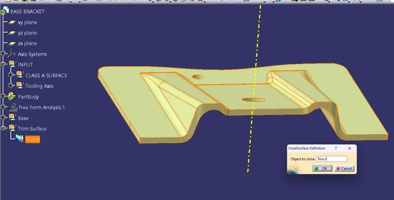
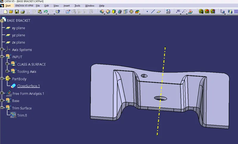
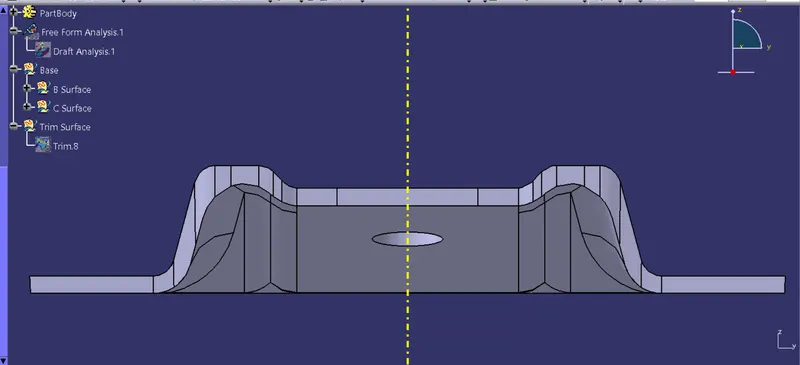
Front View
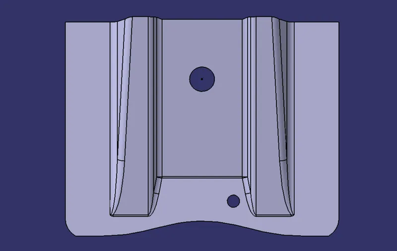
Top View
Side View
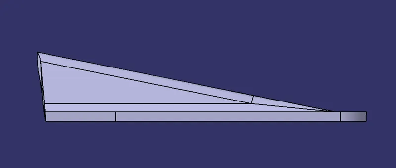
Isometric View
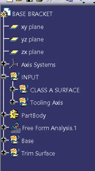
Tree Structure
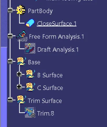
CONCLUSION
Created the Base Bracket Plastic component through the given Class-A surface.