Week 9 - Challenge 2 - Switch Bezel Design
AIM
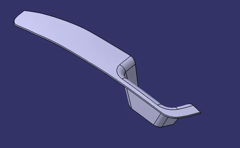
To create the Switch Bezel Plastic component through the given Class-A surface.
THEORY
- Class A Surfaces:
Class A surfaces are the highest quality surfaces with extremely tight tolerances and flawless aesthetics. These surfaces are typically used for visible parts of a product that end-users directly interact with or see. Examples include exterior car body panels, dashboard elements, and consumer electronics housings.
- Class B Surfaces:
Class B surfaces are of a lower level of quality compared to Class A surfaces but are still important for the overall appearance and function of a product. These surfaces are used for components that may not be directly visible to end-users but are necessary for the product's operation and aesthetics.
- Class C Surfaces:
Class C surfaces are the lowest level of surface quality and precision. These surfaces are used for internal components or areas of a product where aesthetics are not a primary concern.
Draft analysis and the tooling axis
- Draft Analysis
Draft analysis, also known as draft angle analysis, is a process used to evaluate the draft angles on a part's surfaces. Draft angles are the angles or tapers added to the vertical surfaces of a 3D model or part. These angles are necessary for certain manufacturing processes, such as injection molding, die-casting, or pattern-making for sand casting.
The purpose of draft angles is to facilitate the easy removal of the part from the mold or tool during the manufacturing process. Without appropriate draft angles, parts may get stuck in the mold, resulting in damage to the part or difficulties in production.
In a draft analysis, a CAD software (like CATIA) evaluates the selected surfaces or faces of a 3D model to determine if they have sufficient draft angles. The software visually highlights areas that do not meet the specified draft angle requirements, helping designers ensure that the part can be successfully manufactured without any issues.
- Tooling Axis Creation
Tooling axis creation, also known as parting line creation, is a process used in CAD software to define the separation plane between two halves of a mold used in manufacturing processes like injection molding or casting. The mold is typically composed of two halves that open and close to produce the final part.
The tooling axis or parting line determines the boundary where the two mold halves meet and separate. It is essential to create a smooth and feasible parting line so that the mold can open and close easily without causing any damage to the part.
PROCEDURE
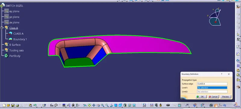
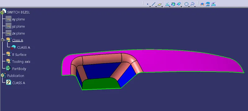
Step 1 : Create new geometrical set for adding the Tooling axis and B surface .Examin the class A surface for continuity and then publish the Class A surface.
Step 2 : Creating tooling axis
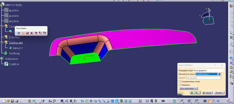
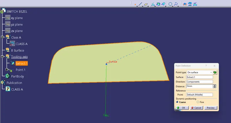
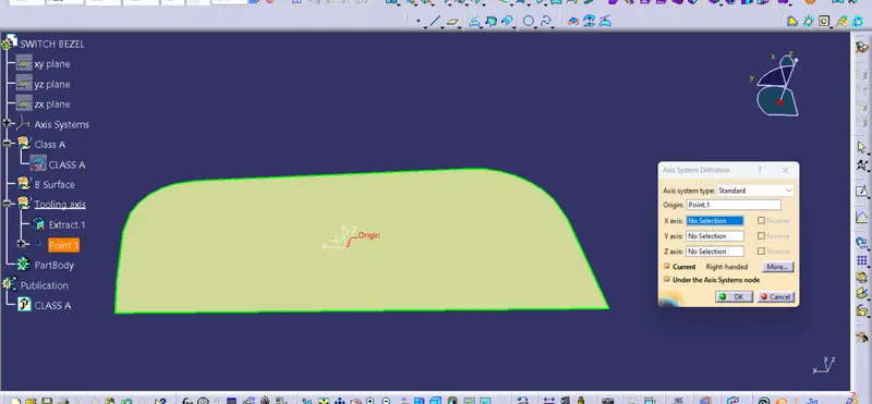
- Using the given class-A surface with the extract command extract the base surface of the pocket and create a midpoint on the extracted surface.
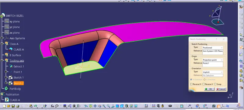
- Insert a new axis system with respect to the point created.
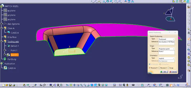
- Create a positioned sketch on the y-z plane and using the project 3D element, project the wall faces on the y-z plane.
- Then draw2 lines and which coincide with projected faces.
- Using the two lines a bisecting line is made.
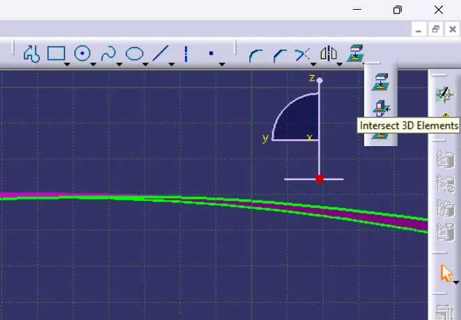
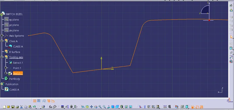
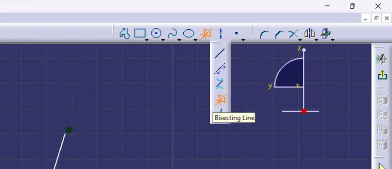
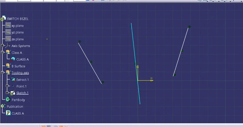
- Now we have to make an intersection line along the x direction, create a sketch on the x-z plane and now we have face only on one side. Create an intersection or project the surface and create on line on it which coincide with wall.
- Since we have only one wall for the other wall create a line on the point we created earlier and make it at an angle 6 degree with the face, further editing on the angle is done after doing the draft analysis.
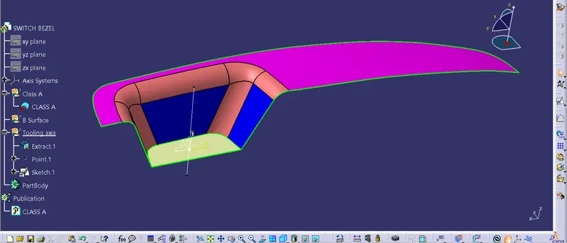
- Now we will get two lines,by bisecting these two lines we will get the 'Main tooling axis'.
- After getting the tooling axis publish it.
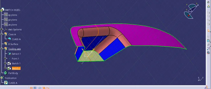
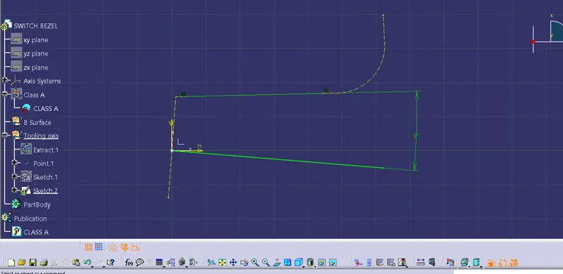
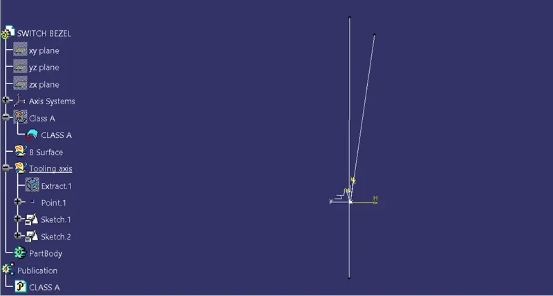
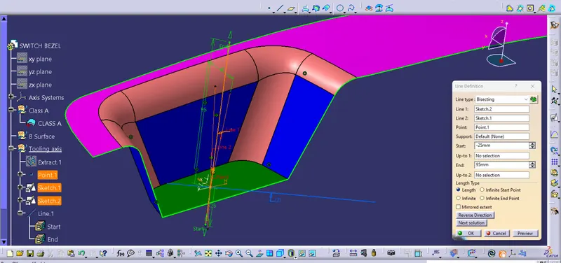
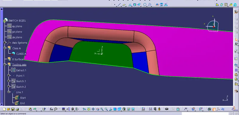
Here we can see all the surfaces so the tooling axis seems to be correct.
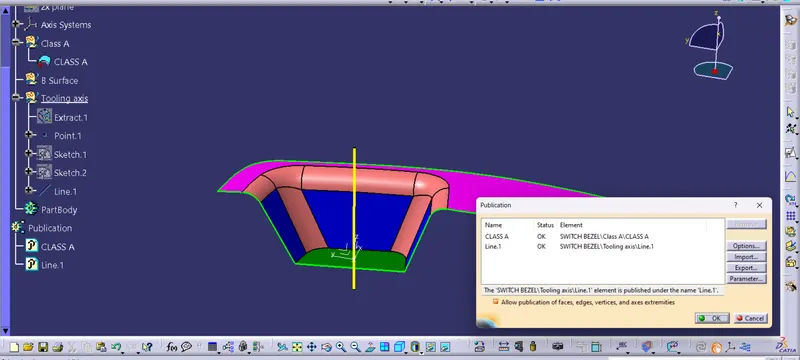
Step 3 : Now conduct the draft analysis
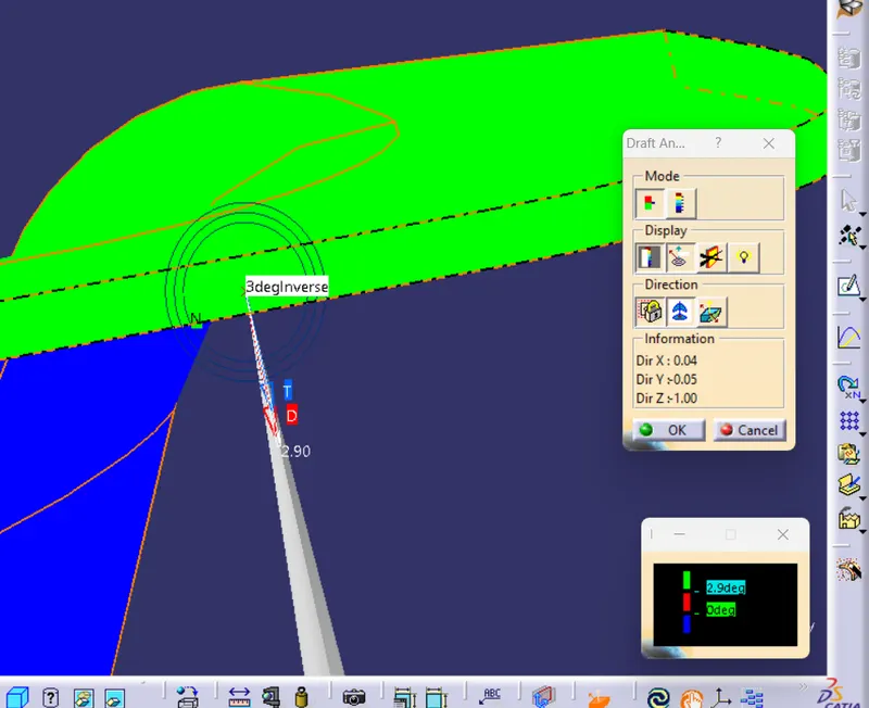
- Draft analysis is done after determining the tooling axis, draft analysis is used to check whether the minimum draft (3 degrees) is maintained or not.
- Change the view mode of the component to be in customized parameter mode and then select the shading mode as materials.
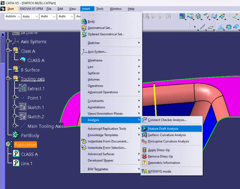
- Then open the featured draft analysis tool from the insert menu.
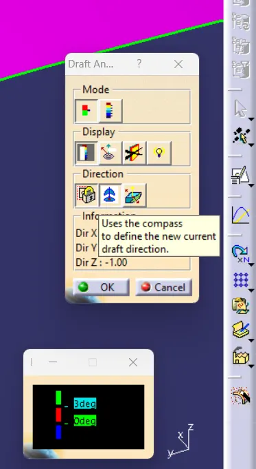
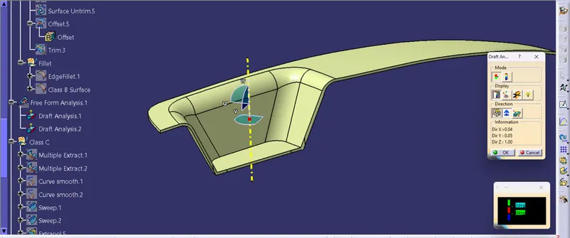
- Then click on use the compass to define the current drafting direction and then drag and align the compass on the Tooling axis.
- Then lock the draft direction and perform draft analysis by clicking on the component.
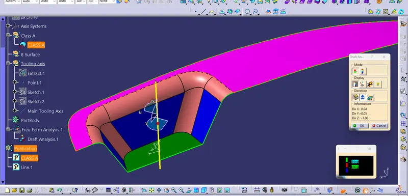
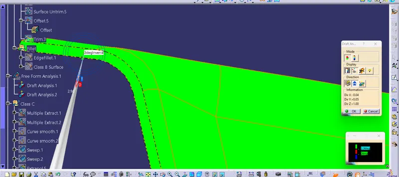
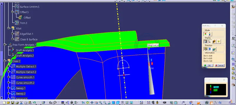
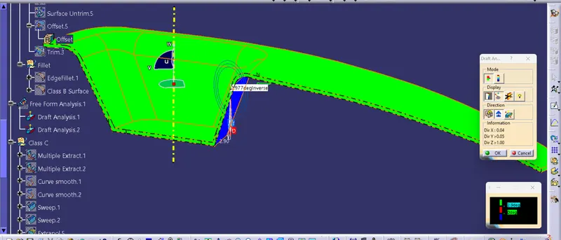
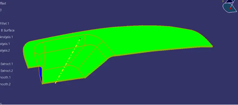
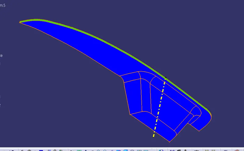
- The green colour indicates the positive daft tooling direction and the given surface passes the draft analysis.
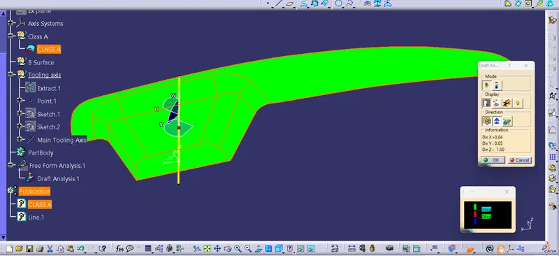
- Select the analyses under the running point to check the draft analysis on the individual faces. It shows how much draft on specific points when the cursor pointer is moved.
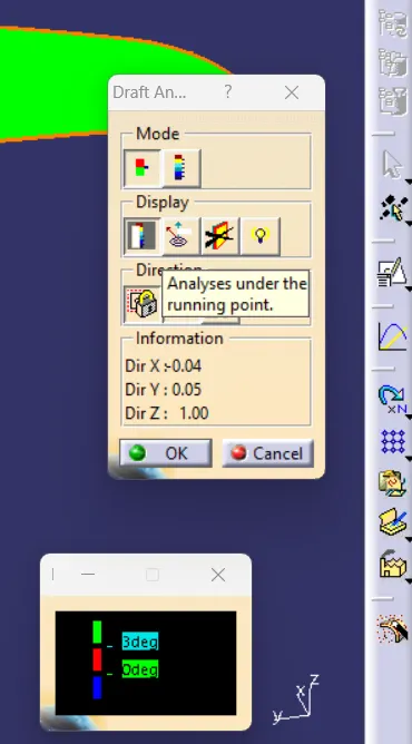
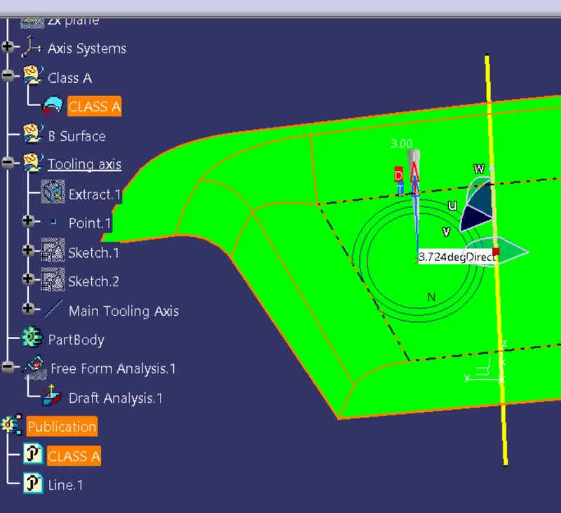
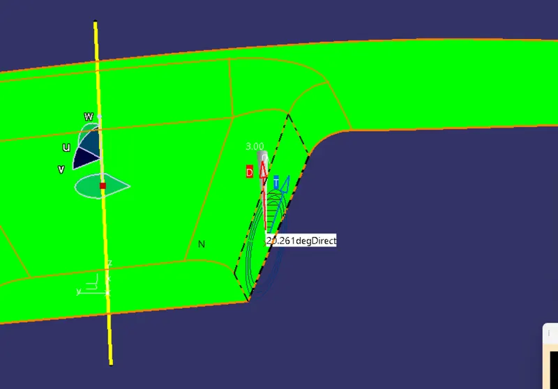
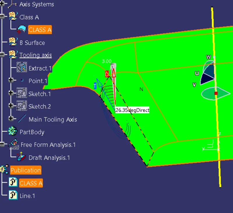
Step 4 : Once the draft analysis has completed the next step is to make the B Surface.
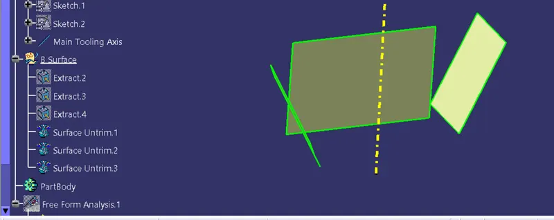
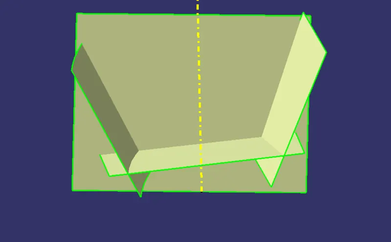
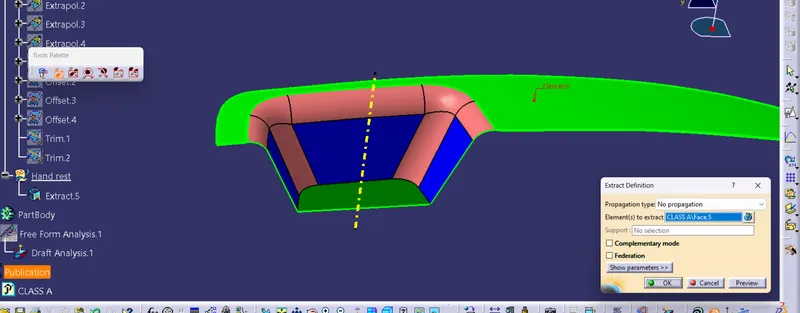
- Extract all the surfaces using 'Extract' command
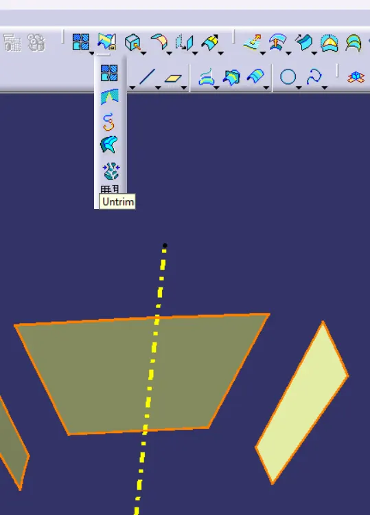
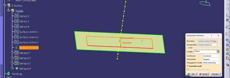
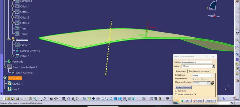
- Unsing 'Untrim' command untrim the surfaces to planes.
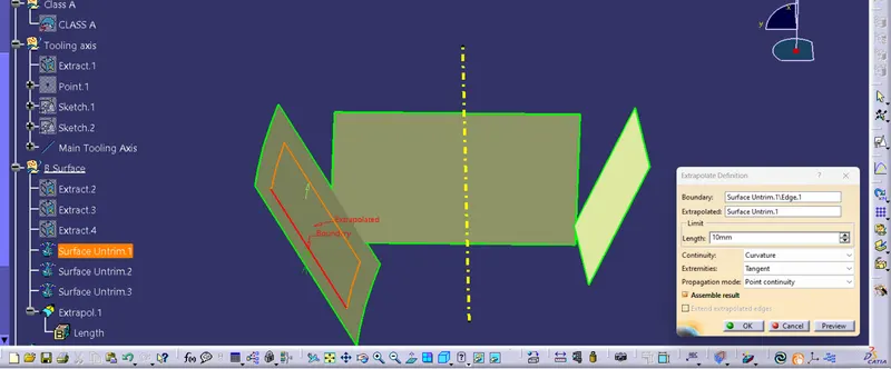
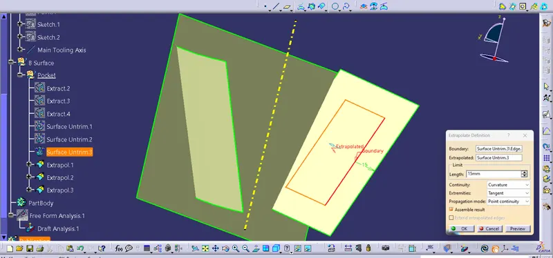
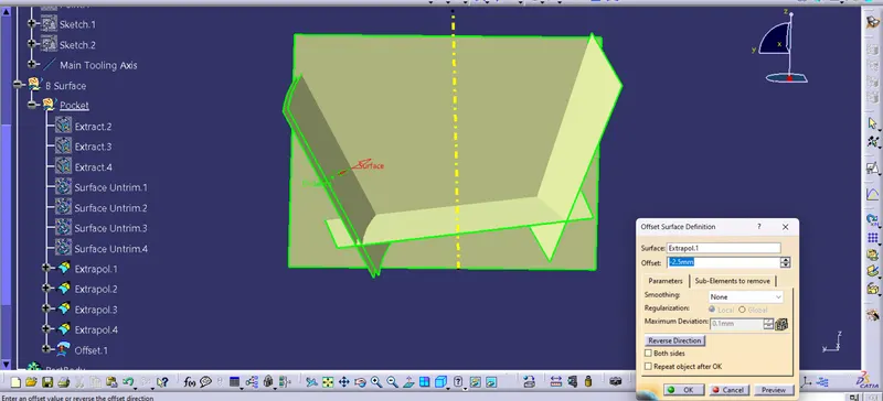
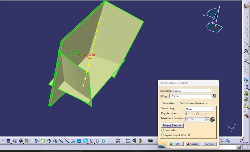
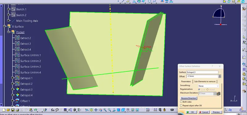
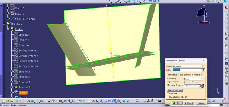
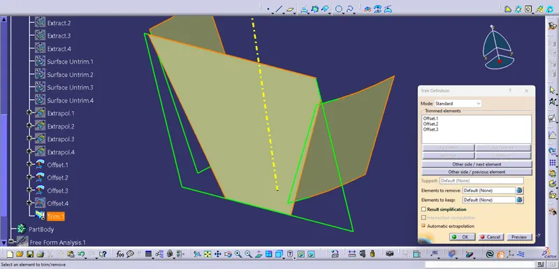
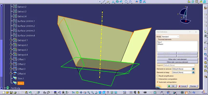
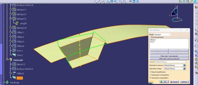
- Extrapolate the surfaces and using 'Offset' command offset the planes at 2.5 mm below the Class A surface,which is the thickness of the body.
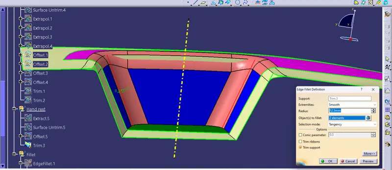
- Then create the fillet; Fillet radius for class B surface = fillet radius of class A surface ± wall thickness.
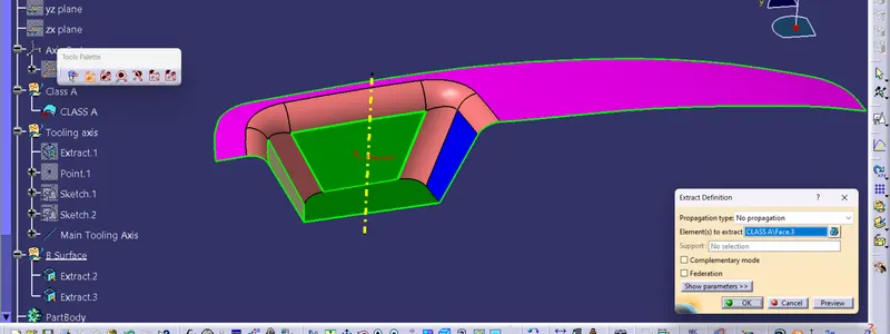
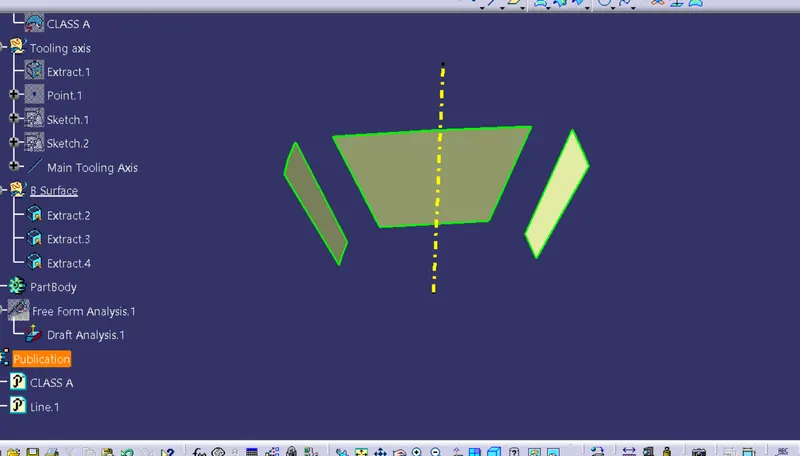
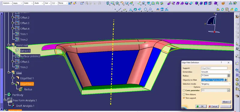
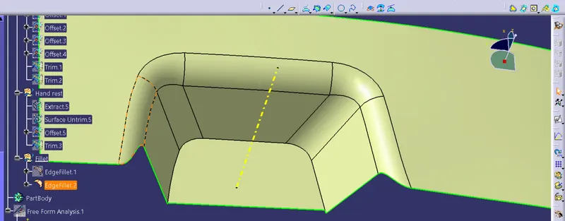
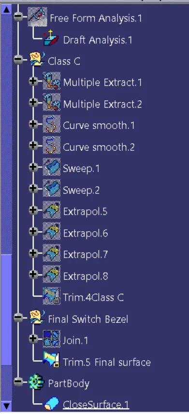
Step 5 : Next we have to create the Class C surface.
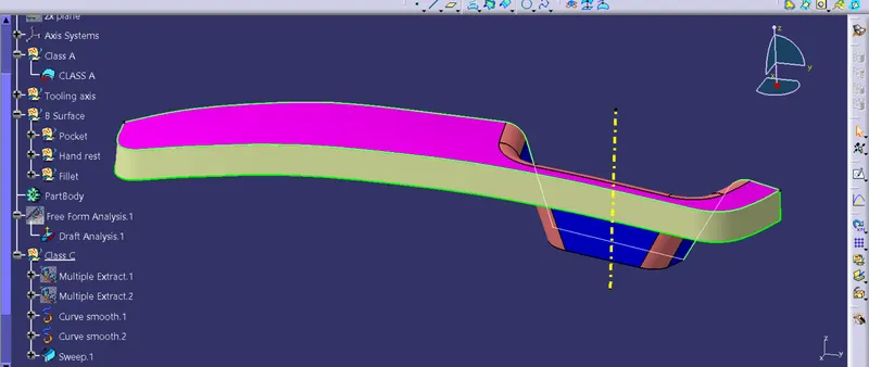
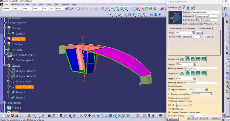
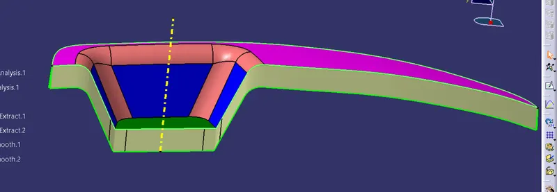
Create the boundary of the CLASS-A surface using multiple extract command and then smoothen it using 'Curve Smooth' command.
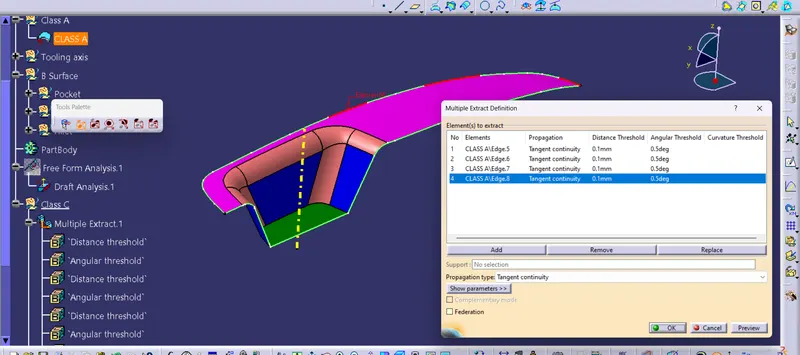
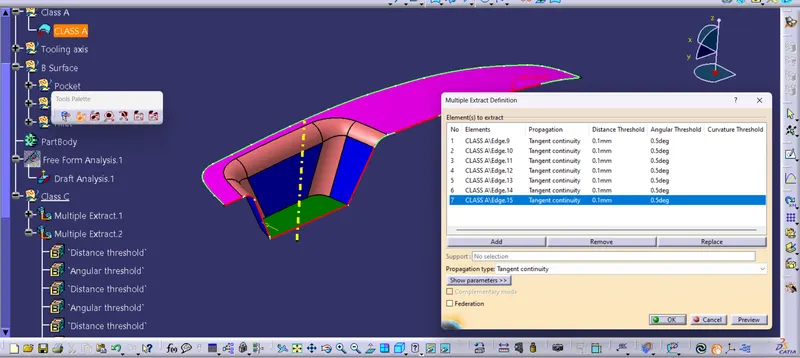
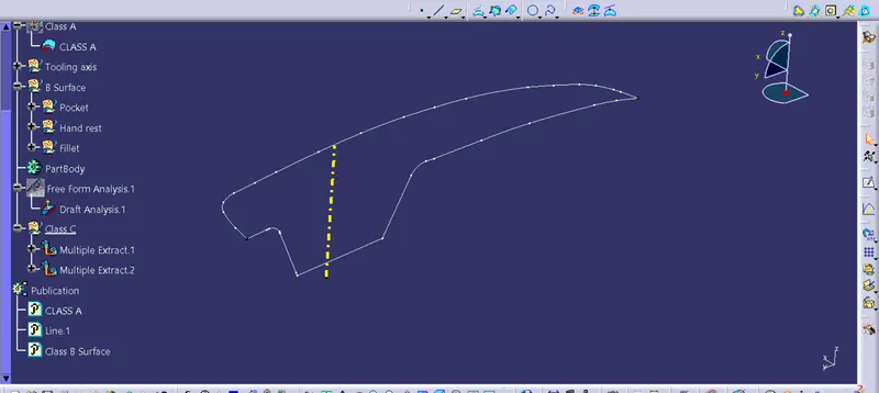
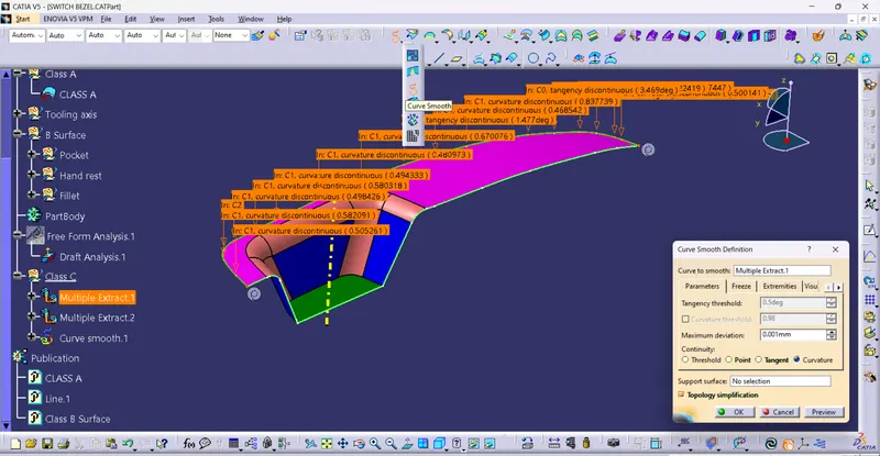
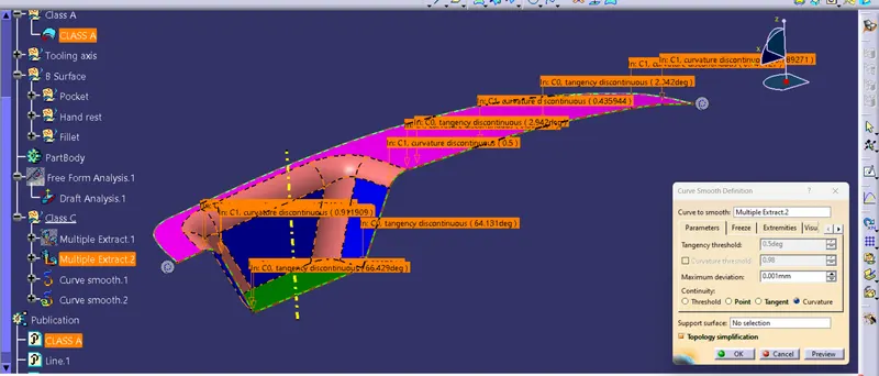
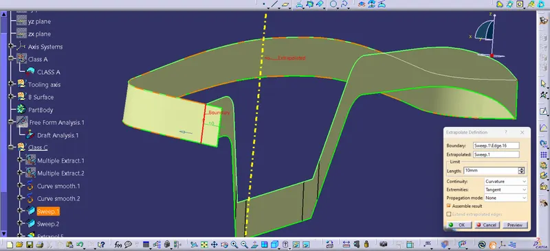
- Using the sweep command to create the sweep profiles of the two curves.
- The sweep surfaces are joined together by extrapolating it and trim with each other.
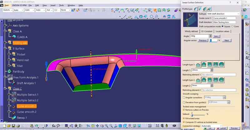
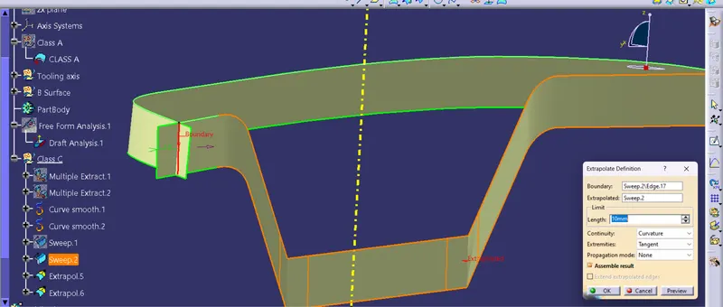
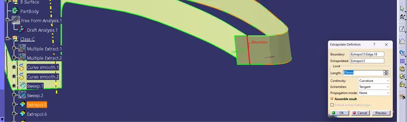
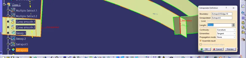
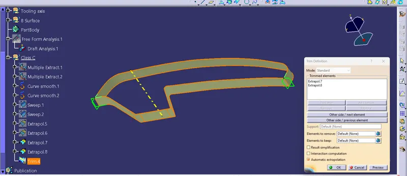
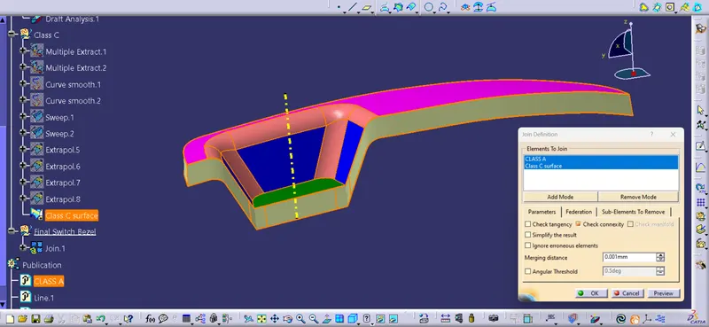
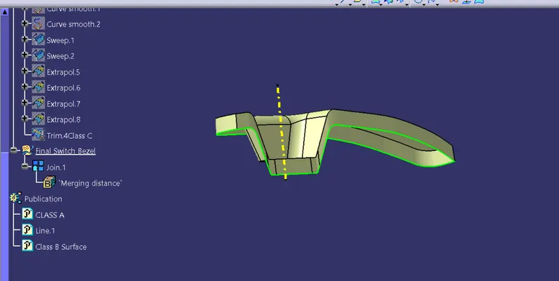
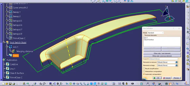
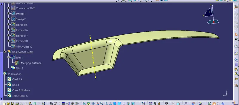
Step 6 : Making the final surface of the switch bezel by joining Class A with Class C and then triming it with Class B.
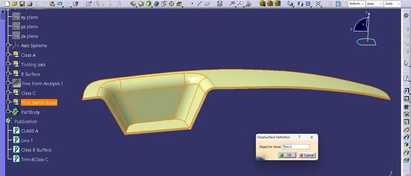
Step 7 : Switch to 'Part Design workbench' and using 'Close surface command convert the surface into solid part body.
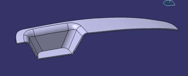
Front View
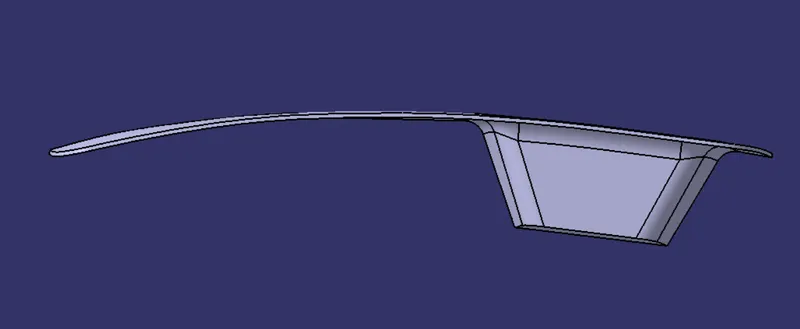
Side View

Top View
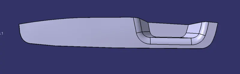
Isometric View
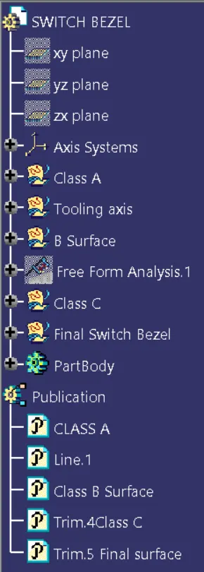
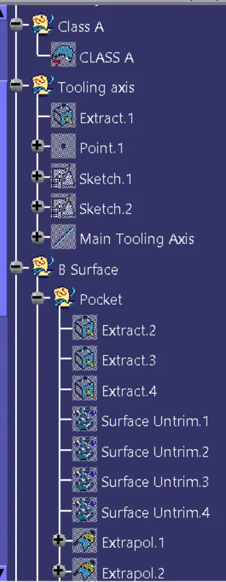
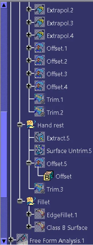
Tree Structure
Draft Analysis of Solid part body
CONCLUSION
Created the Switch Bezel Plastic component through the given Class-A surface and Conducted Draft analysis.