Project 2 - Wiring harness routing on given car body
AIM
To route the Wiring harness on Given car body and Prepare flatten view drawing in CATIA V5.
OBJECTIVE
- To create the wiring harness routing for the given Car body by using appropriate connectors, clips and clamps which is required.
- To create a flatten view drawing file in Catia v5.
- Need to apply the protection covering like cot tubes and insulation tapes to the bundles as required.
- Need to apply the industry best packaging rules and best practices studied in this course.
THEORY
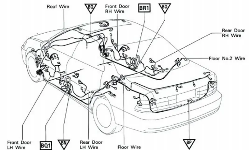
The car tailgate door wiring harness is a specialized electrical component in an automotive vehicle that connects various electrical systems and components located in the tailgate door. It is responsible for transmitting power and signals to and from the various electrical devices in the tailgate, such as the rear lights, wiper motor, defogger, central locking mechanism, and other accessories.
Here are some key details about a typical car tailgate door wiring harness:
-
Structure and Design: The wiring harness is a bundle of wires, connectors, and protective sheathing that is designed to withstand the environmental conditions encountered in the tailgate area. It is usually made of several individual wires, each with their own color-coding to aid in identification and connection.
-
Connectors: The harness includes connectors at each end, allowing it to be easily connected to the vehicle's main wiring system and the various electrical components in the tailgate. These connectors ensure a secure and reliable connection while allowing for easy removal or replacement if needed.
-
Wire Types: The wiring harness comprises different types of wires to accommodate various electrical needs. For instance, there are power wires that carry high-current electricity for components like the wiper motor or rear lights, as well as signal wires for controlling functions like the defogger or central locking mechanism.
-
Protective Sheathing: To protect the wires from damage due to abrasion, moisture, or other hazards, the harness is typically covered with a protective sheathing. This sheathing is usually made of durable materials like plastic or rubber and provides insulation and mechanical protection.
-
Routing and Mounting: The wiring harness is routed within the tailgate in a specific manner to ensure proper organization and prevent interference with moving parts, such as the hinges or latch mechanisms. It may be secured using clips, straps, or adhesive tapes to keep it in place and prevent it from getting tangled or damaged.
-
Integration with Vehicle Systems: The tailgate door wiring harness is integrated into the overall electrical system of the vehicle. It connects to the main wiring harness, which runs throughout the vehicle, allowing for communication with other systems, such as the body control module or the vehicle's computer.
Packaging rules and assumptions made in this project:
- Avoid harness routing and clipping in a blind zone.
- Avoid harness routing through the small structural holes and openings to minimise the chaffing and handling of the wiring harness during installation.
- Provide additional slack to the harness according to the surrounding and harness bending requirements. And avoid excess slack to the harness.
- Provide sufficient clearance to the different surrounding parts.
- Avoid routing over the bolts, near to the bolted joints or screwed joints. Because it may damage the harness or may puncture the harness.
- Avoid routing near the sharp edges like thin sheet metal brackets, panel joints, etc.
- Provide at least 100mm clearance to the harness from the ABC pedals, clutch lever & cables, Engine timing belt or any other dynamic components.
- Enough clips and clamps should be provided to ensure the positive clearance with the surrounding and safety of the wiring harness.
- Ensure distance between two clamps on a straight branch should be maximum of 200mm.
- Clamping requirements should be decided based on the harness bending, surrounding and mounting arrangements.
- Provide positive clamping at the engine and chassis to avoid the harness damage when Engine rocks.
- Keep harness away from the transmission dynamic assemblies like drive shaft or propeller shaft.
- Provide the guiding channel if it is required.
- Use the rubber gromets which provide the proper sealing, and also protects the harness from the sharp edges and absorbs the vibrations.
- Wiring harness minimum branch length should be 50mm.
- Minimum distance between the clip and nearest branching point should be atleast 25mm.
- Minimum distance between two breakouts should be 50mm.
- Limit the number of branches coming out from the single branch to 4.
- Provide the bracket for the interconnection connector parking.
PROCEDURE
Step 1 : Observe the component and make a list of compontents required for the harness routing.
Here I am going to consider the wiring harness routing is done only for Two brake light and Two lights for Number pate only which will be combined to a inter connection connector.
As per the obervation the following components are required:
* 776438-1 - One 12 pole connector for interconnection connector.
* DT06-4S - Two 4 pole connectors for Brake lights.
* DT06-2S - Two 2 pole connectors for Number plate light
* 10mm Fir Tree Clip
* 8mm Fir Tree Clip
* 5 mm Fir Tree Clip
Step 2 : Define the mechanical components and convert them into electrical parts and prepare the catalogue for the same:
- Imported the STP file of the connector into Catia V5 and saved as a CATPART file.
- Switched to part design workbench and created points at the front face and mating face of the connector.
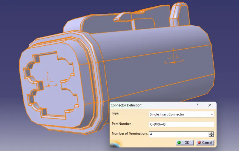
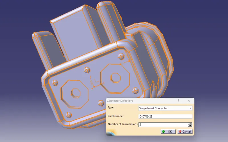
- Switched to electrical part design workbench and defined the connector electrically by using the command 'define connector'.
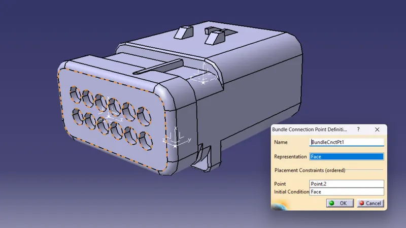
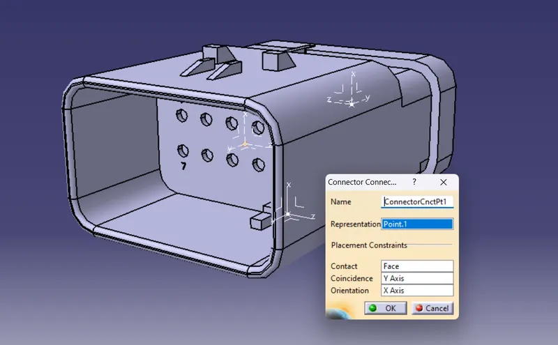
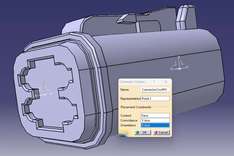
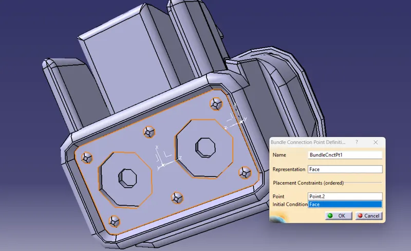
- And also created the bundle connection point, connector connection point and the cavity connection point of the connector. And saved the connector file into the catalogue which is already created and saved into the device.
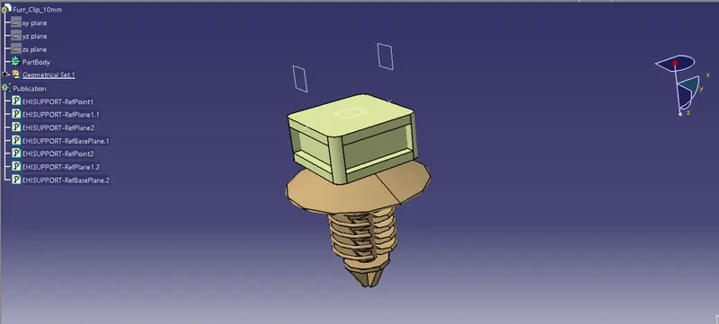
2.1. Defining Fir tree clip of 10mm ,8mm 5mm and adding them to catalogue created
- Import the STP file of fir tree clip rounded into the Catia V5 and save as a CATPART file.
- Now switch to part design workbench and create entry point and exit point for the clip by using the point command.
- Then create the entry plane, exit plane, and base for the clip.
- Now switch to the electrical part design workbench and define the clip by using the command define support part.
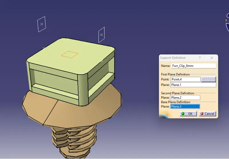
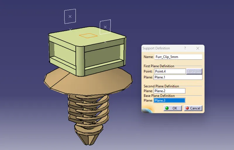
- Now define the first point, first plane, second plane and base plane of the clip.
- Fir tree clip of 10mm
- Fir tree clip of 8 mm
- Fir tree clip of 5 mm
A Catalogue was created with 3 Family and the 10mm fir tree clip is added to the clips family:
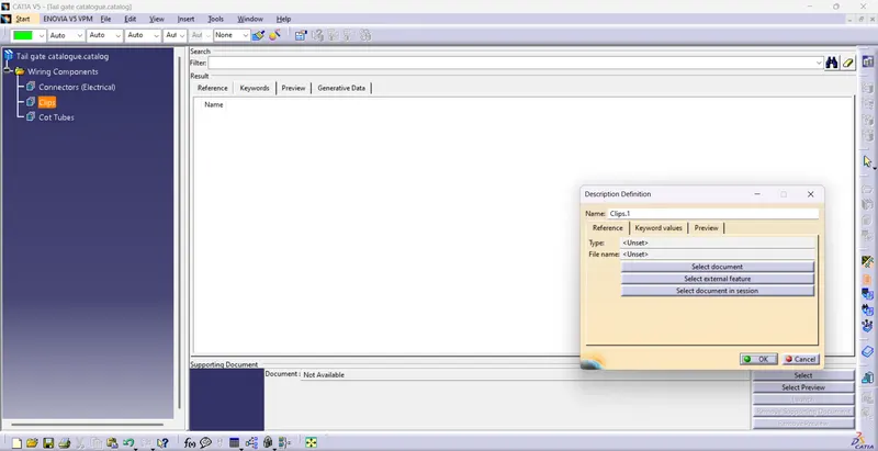
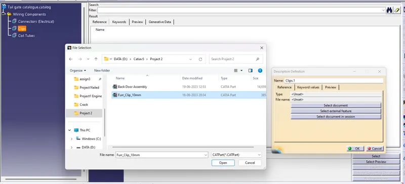
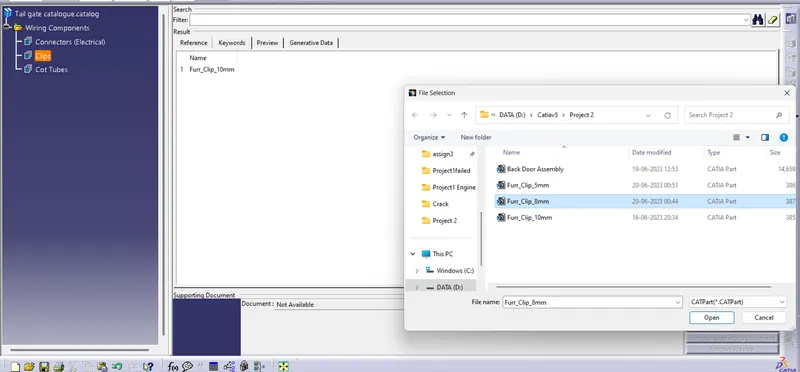
8 mm fir tree clip is added to the clips family:
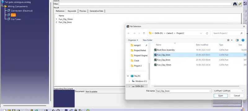
5 mm fir tree clip is added to the clips family:
2.2 Defining Connectors geometrical parameters and converting them to electrical components and then adding to Catalogue created:
- 776438-1 12 pole Inter connector
- DT06-4S - Two 4 pole connectors for Brake lights.
- DT06-2S - Two 2 pole connectors for Number plate lights.
Adding Connectors to Catalogue created:
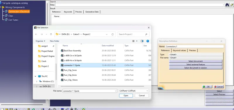
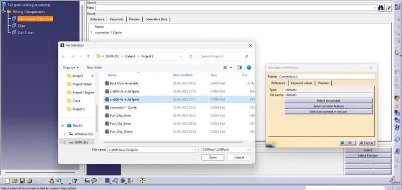
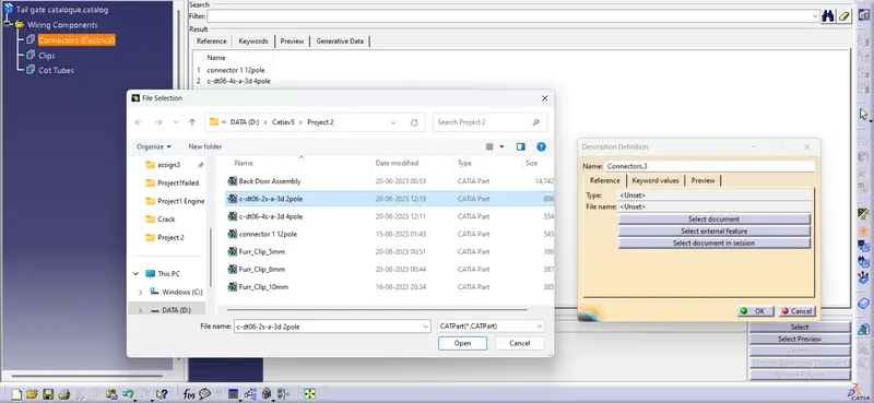
Step 2.3 : Creating required Corrugated tubes and adding them to Catalogue:
- 10 mm Corrugated tube
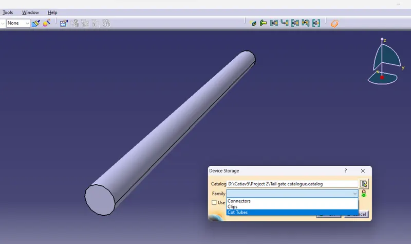
- 8 mm Corrugated tube
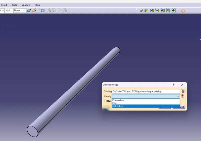
- 5 mm Corrugated tube
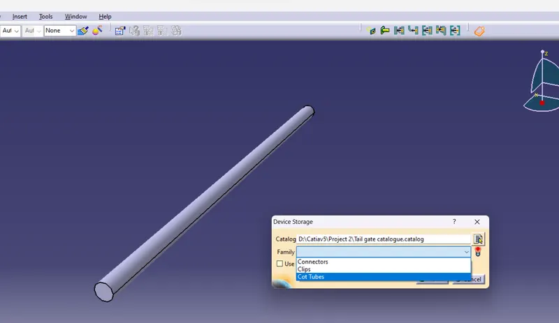
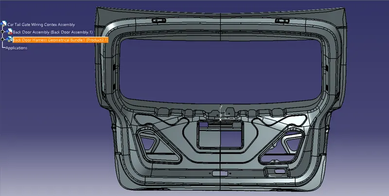
Step 3 : Creating Context Assembly and adding the Door CAD data and Geometrical Bundle for wiring
- A Context Assembly for Door Harness is created which will work as the main assembly.
- A Context Assembly will contain Back Door Assembly data for Back door and Door Harness Geometrical Bundle Assembly.
- Add New product int the Context assembly and rename it as 'Back Door Harness Geometrical Bundle1' and save it in the same folder.
- Add all the required connectors into it and also added the back door file.
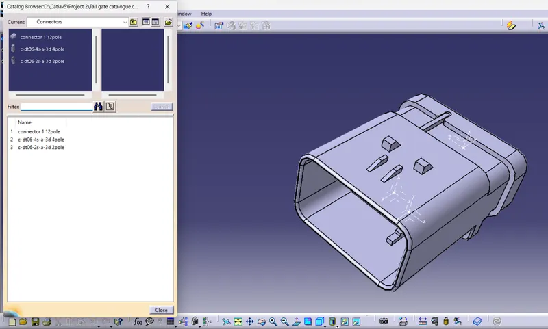
Adding Connectors :
The Geometrical bundle was opened in Mechanical assembly design workbench and then add a connector from the catalogue created.
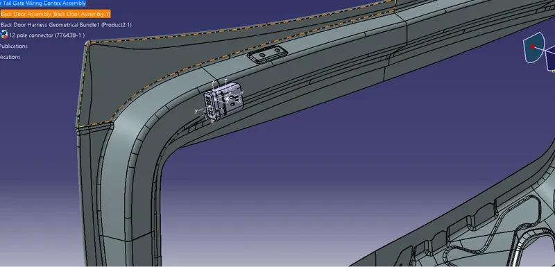
Step 4 : Aligning the imported connectors into required locations using 'Manipulation', 'Snap' and Compass for routing the wiring harness.
Importing and aligning DT06-2S
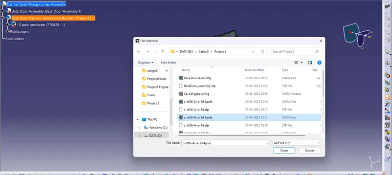
Importing and aligning DT06-4S
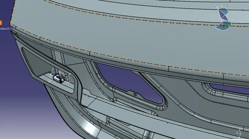
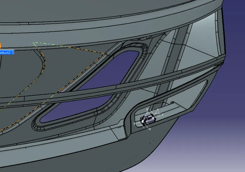
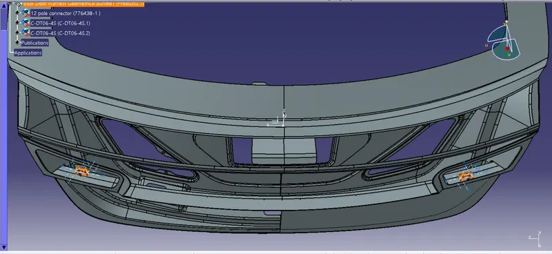
Importing and aligning DT06-2S
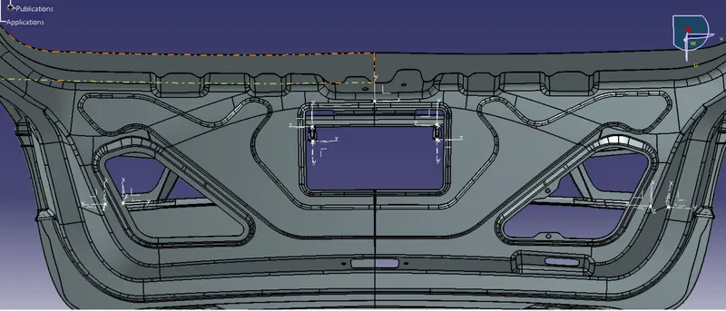
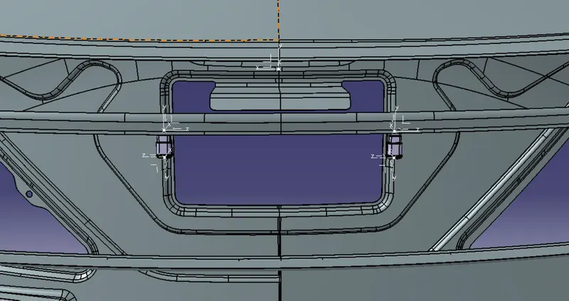
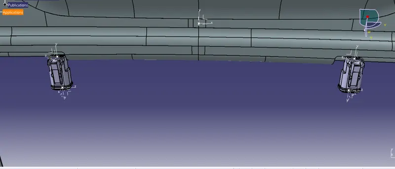
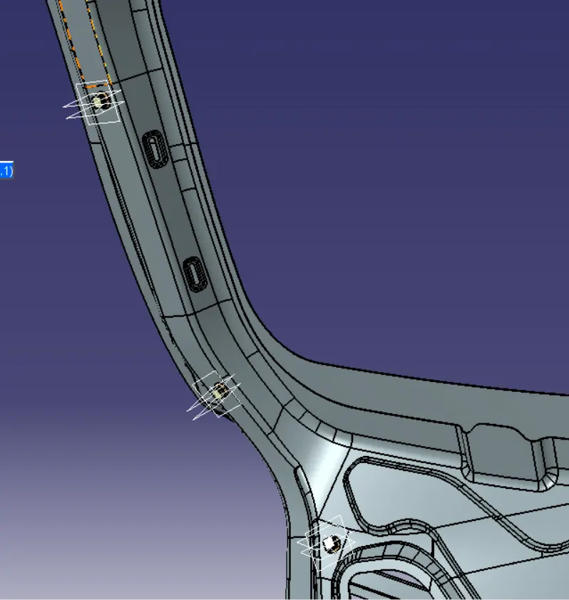
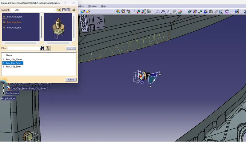
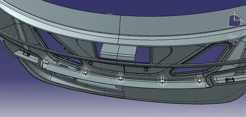
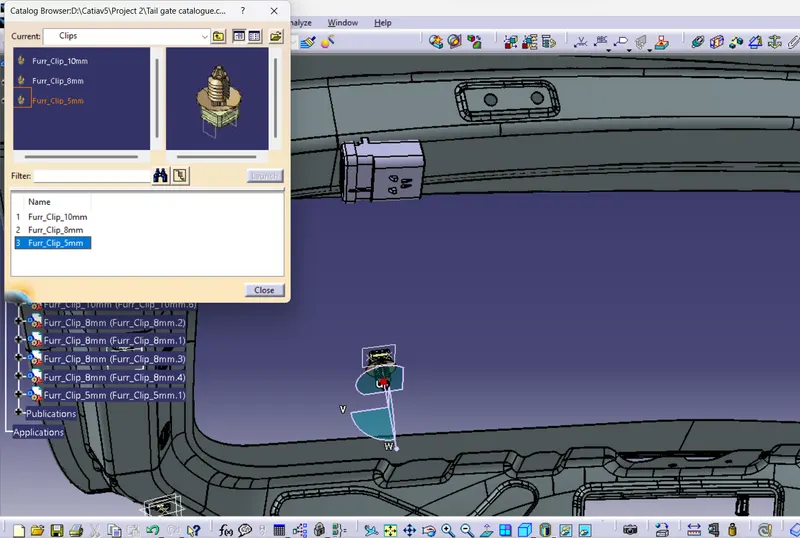
Step 5 : Adding the required sizes of fir tree clip 10mm,8mm and 5 mm from the catalogue for wiring harness routing
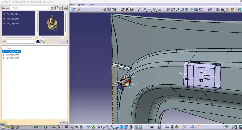
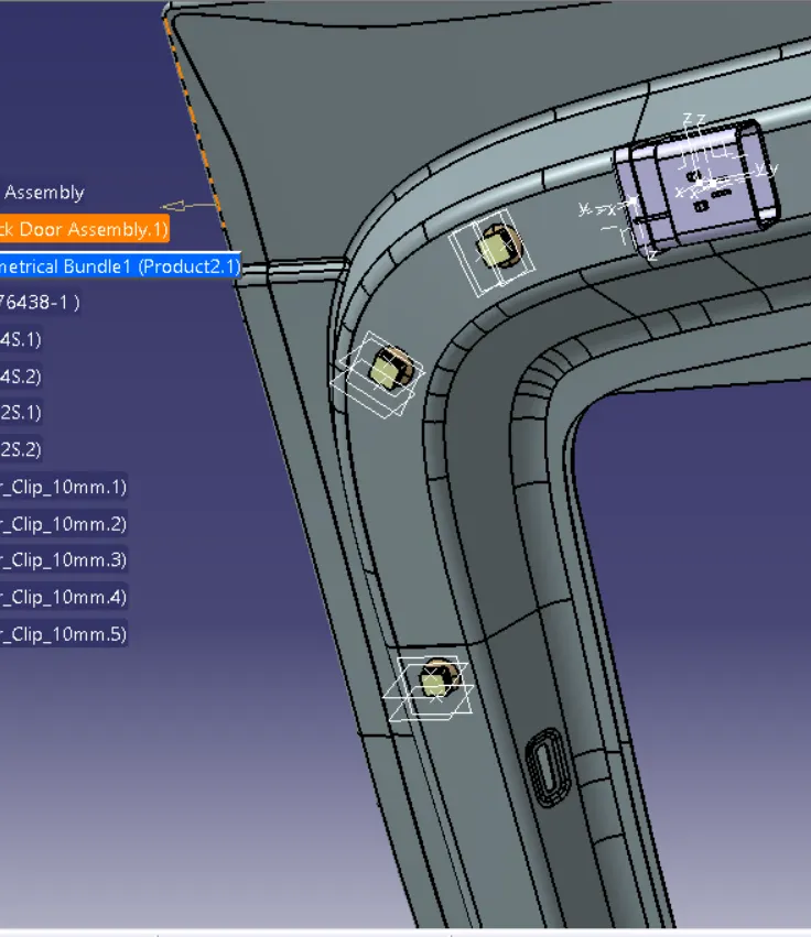
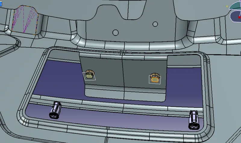
Step 6 : Wiring harness routing
- After inserting and placing all the required connectors and clips required the next step is wiring harness routing.
- Switch to Electrical harness assembly workbench
- Define the assembly as electrical assembly and start routing
The routing starts from the interconnection connector:
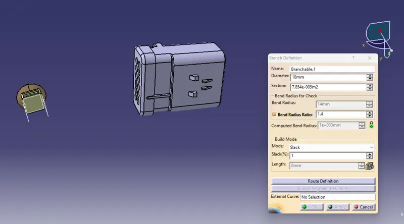
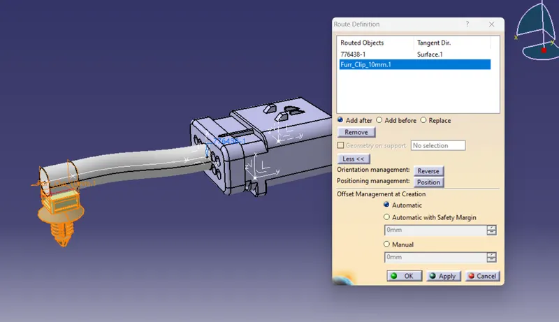
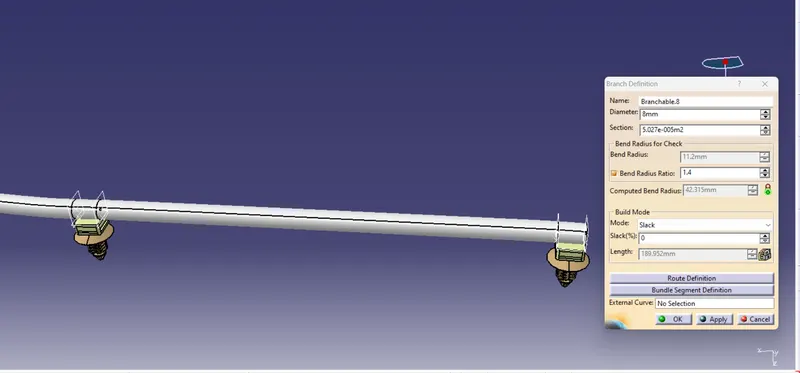
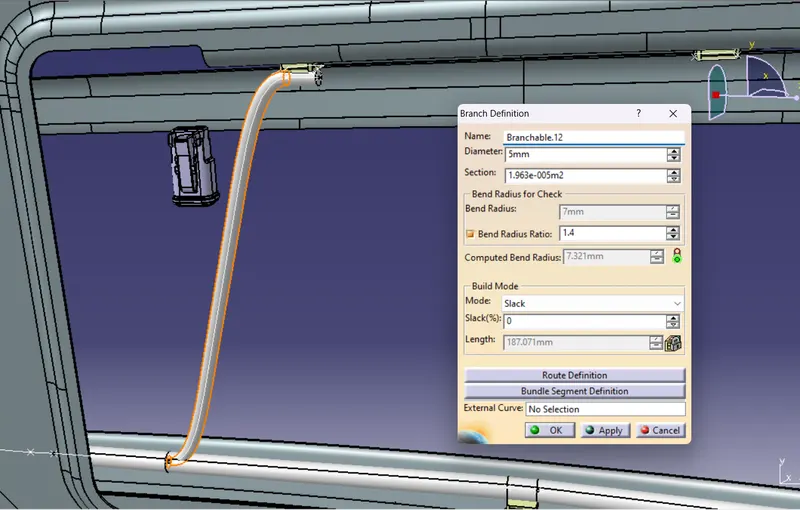
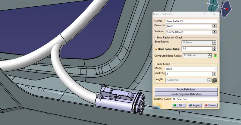
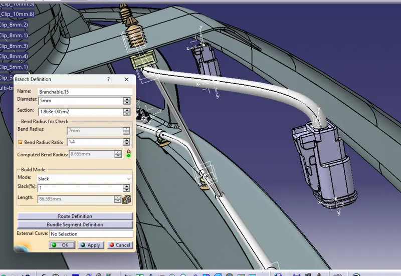
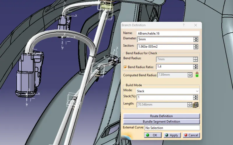
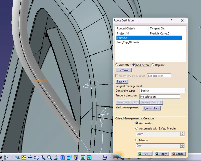
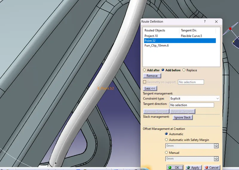
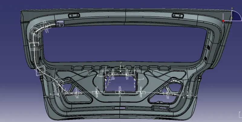
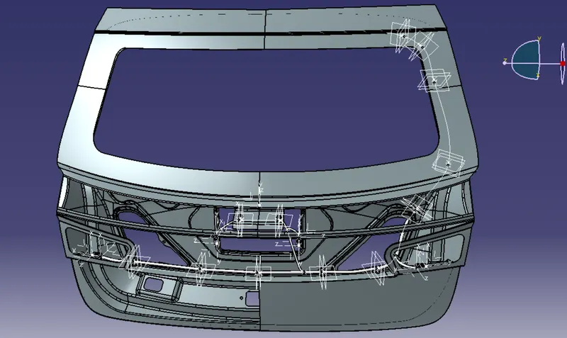
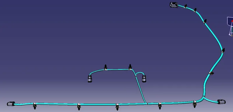
After finishing the wiring harness routing
Step 7 : Checking for Continuity of the routed wiring harness
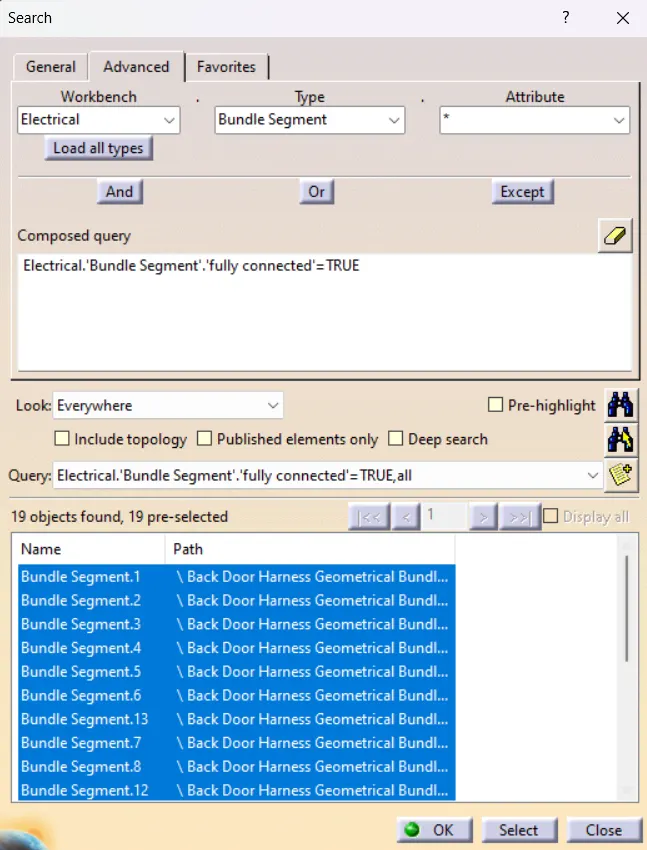
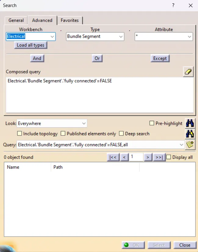
After the checking it is found that all the wiring are connected
Step 8 : Applying the Corrugated tubes as required.
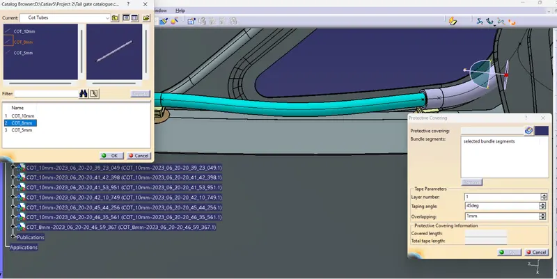
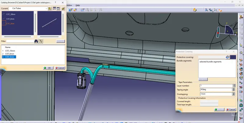
After applying Corrugated tubes
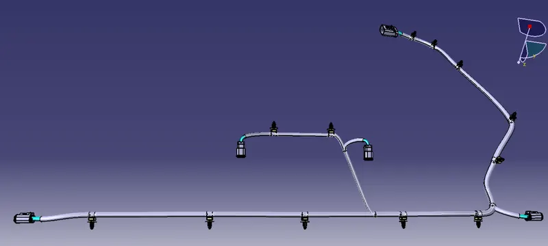
Step 9 : Flattening the wiring harness
- Open the flattening workbench and define the flattening parameters.
- Then open the two workbench side by side simultaneously, using extract command bring the wiring harness to flatten workbench.
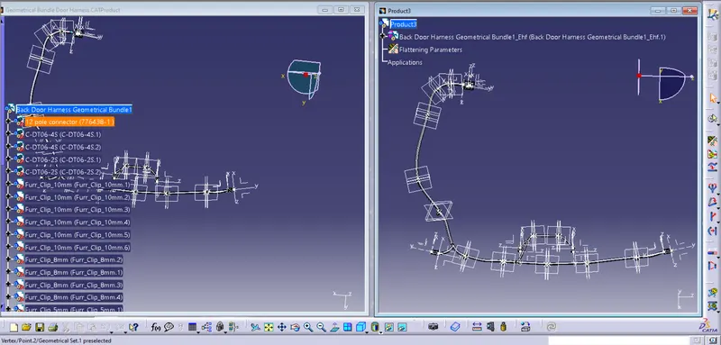
After importing using flatten command flatten the Harness:
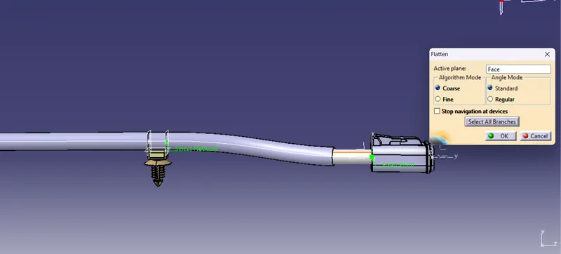
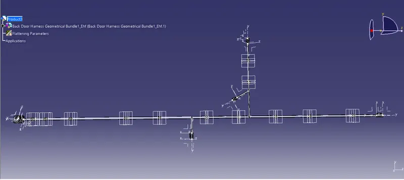
Afer flattening the wiring harness :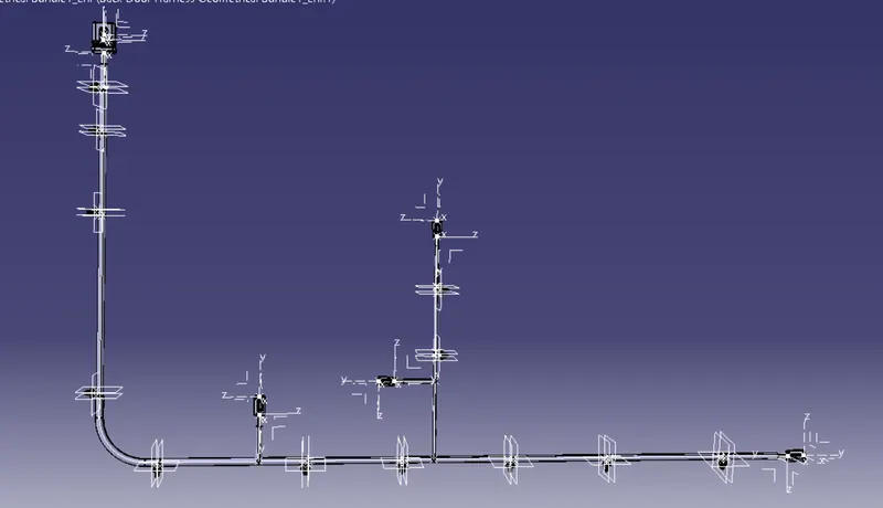
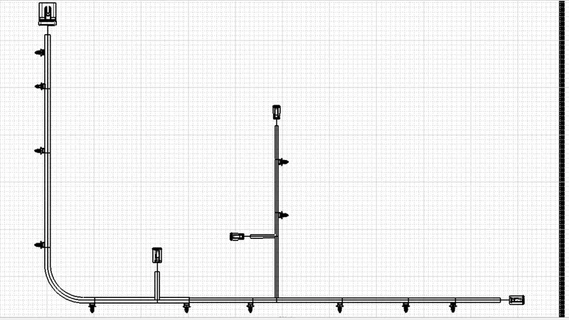
Step 9 : Converting the flattened wiring harness to drawing
- Create a new file of drawing and place the wiring harness flattened view.
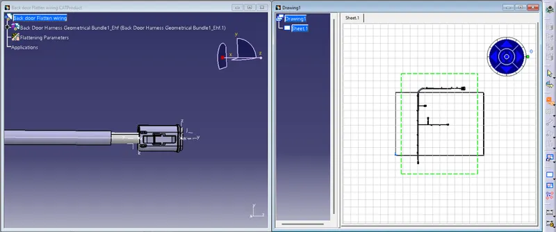
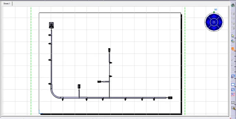
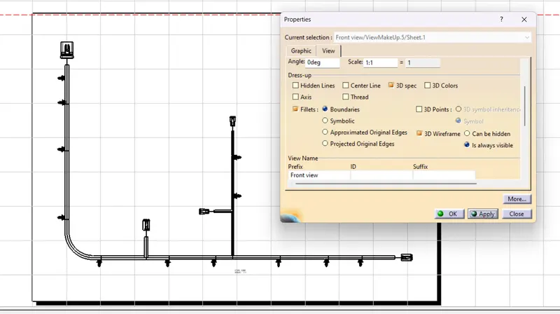
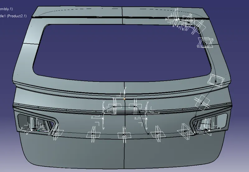
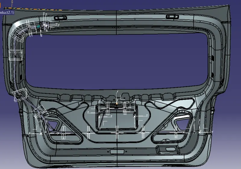
For the convience of wiring harness routing and better visibility some of the parts of the back door were hidden.The below shown is the front and back view of the door after routing and unhiding the car parts.
CONCLUSION
- Created the wiring harness routing for the given Car body by using appropriate connectors, clips and clamps which is required.
- Protection covering like cot tubes and insulation tapes to the bundles are applied as required.
- Wiring harness catalogue is created with all the required connectors, clips and corrugated tubes.
- Checked for the continuity of the wiring harness routed and found all the bundles were connected perfectly.
- Created a flatten view drawing file in Catia v5.
- Made the Drawing of the wiring harness.
REFERENCES