Roof Design
AIM
- To create an assembly for a given roof styling by developing the essential flanges for the outer roof and creating the reinforcements.
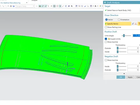
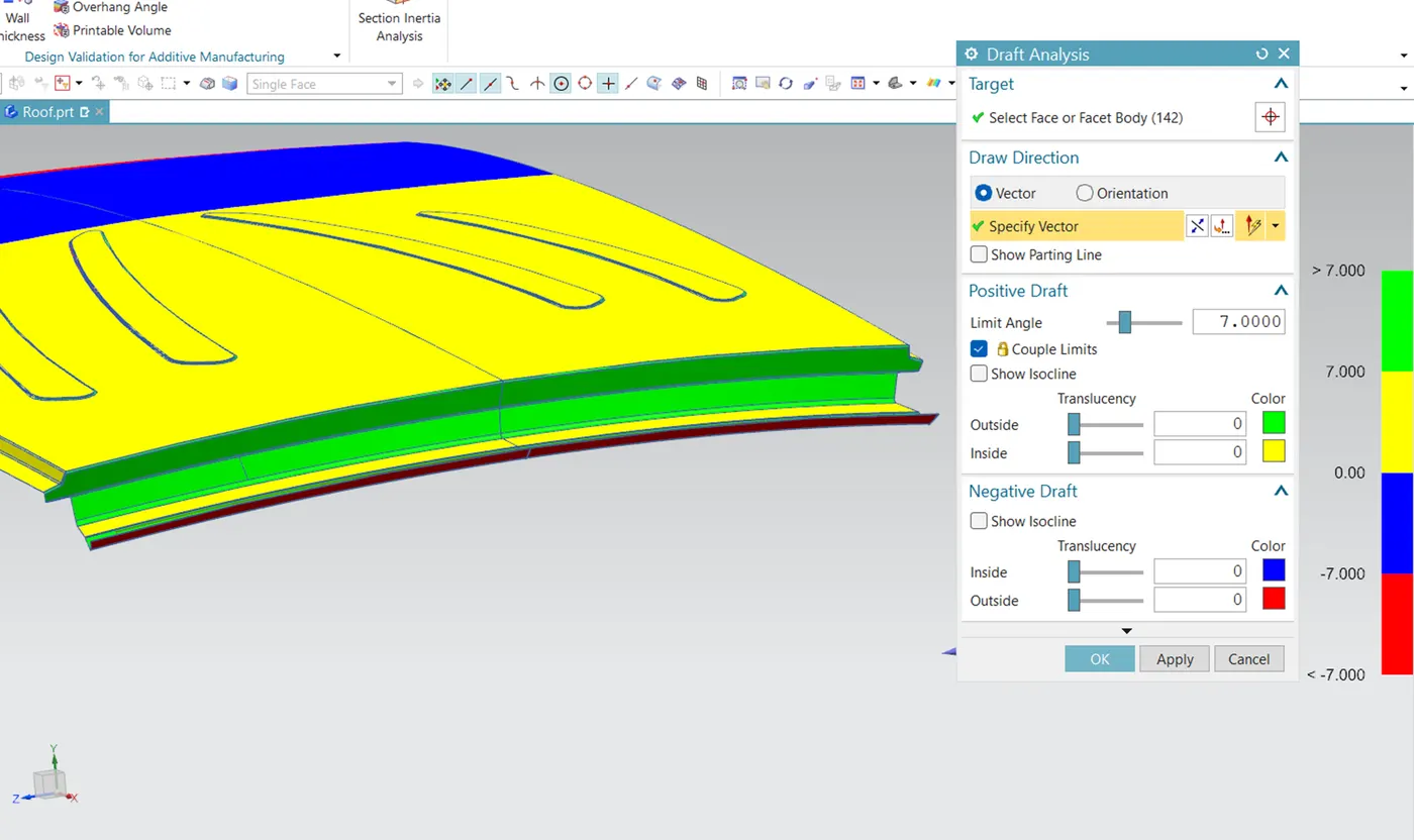
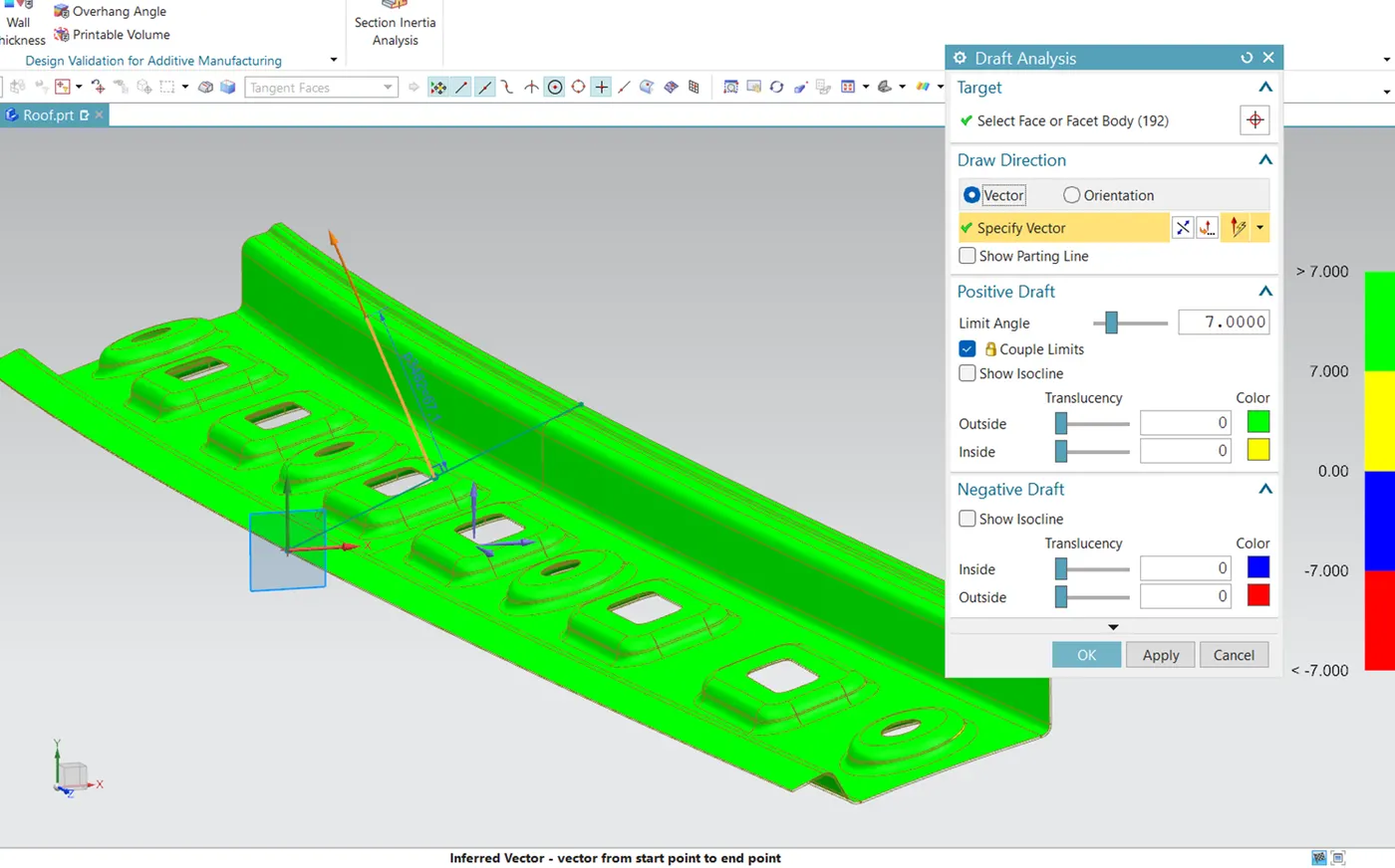
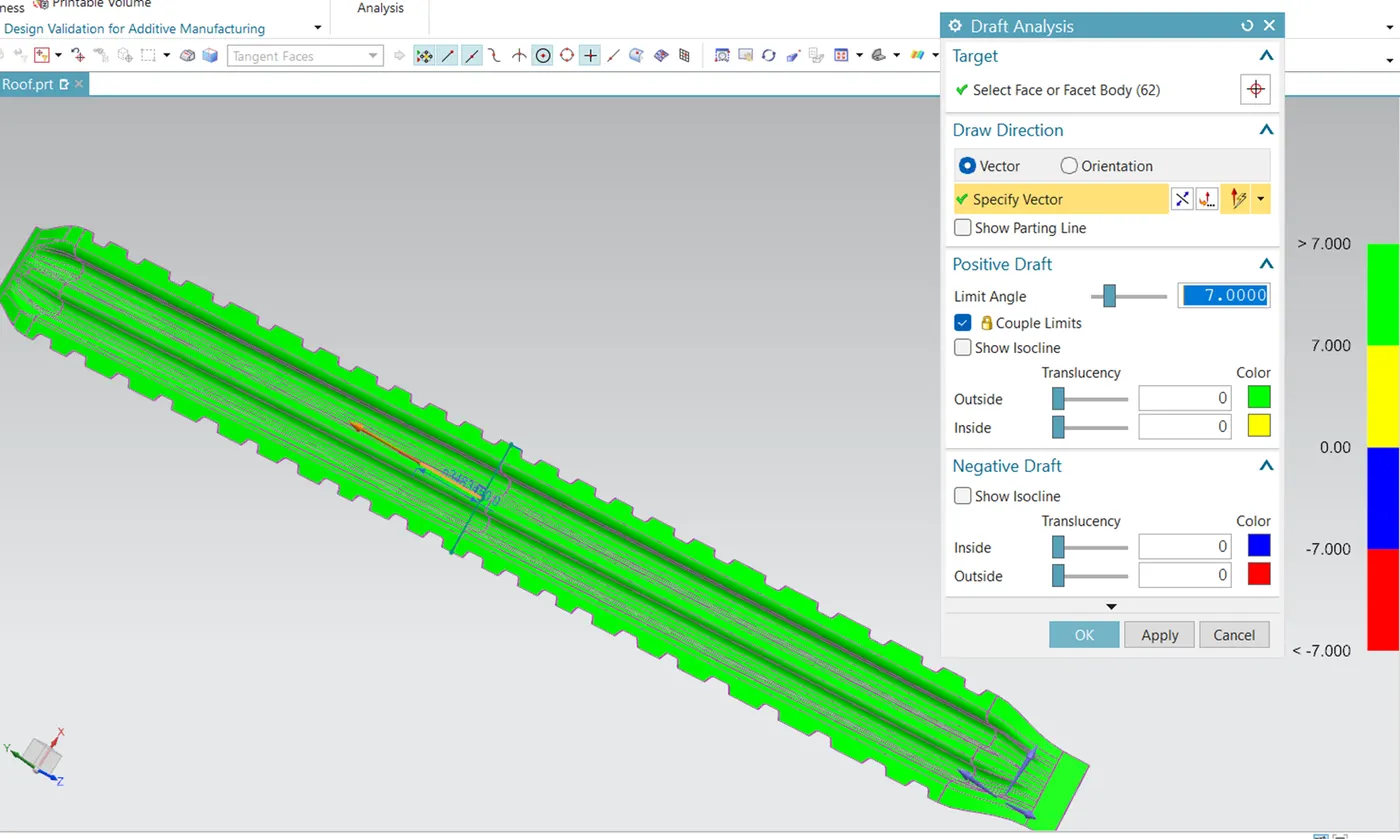
- To conduct draft analysis for ensuring the part clear draft.
- To calculate the Heat distortion, Snow load and section inertia on roof.
Software Used: NX CAD
THEORY
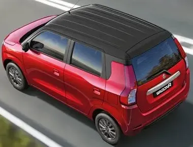
An automobile roof or car top is the portion of an automobile that sits above the passenger compartment, protecting the vehicle occupants from sun, wind, rain, and other external elements. It also joins the vehicle body with the lower parts such as A, B and C pillars. To provide extra protection to the roof, reinforcement are provided in form of rails and bows which also has provsions to mount different attchments.
A car roof serves both functional and aesthetic purposes. Structurally, it provides crucial support to the vehicle, contributing to overall rigidity and safety. Design considerations involve balancing aerodynamics, ensuring optimal fuel efficiency, and minimizing wind noise. Roof materials, such as steel, aluminum, or composite alloys, are chosen for their strength-to-weight ratios. From a stylistic standpoint, the roof plays a key role in defining the car's silhouette, contributing to its visual appeal. Engineers must also account for practical features like sunroofs or convertible options, integrating them seamlessly while maintaining structural integrity. In essence, the car roof exemplifies the intricate intersection of form and function in automotive design.
Types of car roofs :
- Sedan Roof: This is the most traditional roof style, featuring a fixed top with two pillars.
- Coupe Roof: Typically a two-door car with a sleeker, sloping roofline compared to sedans.
- Convertible Roof: Allows the top to be either fully retracted or partially open, offering an open-air driving experience.
- Hatchback Roof: Combines a rear door with a rear window that opens, providing access to the cargo area.
- Wagon Roof: Similar to a hatchback but with an extended roofline and a more vertical rear end, increasing cargo space.
- SUV Roof: Varies widely, ranging from a fixed roof to a panoramic sunroof or even convertible SUVs.
- Targa Roof: Found in sports cars, it involves a removable panel over the front seats, leaving a central roof section intact.
- Sunroof/Moonroof: A movable panel in the roof that allows light and air into the cabin, either tilting open or fully retracting.
The following factors should be considered for the roof design:
- Visibility criteria
- Head clearance for comfort
- Safety Parameters
- Draft analysis
- Heat distortion and Snow Load
Bow–Roof Prediction Formula
W = [1.73 x 10^(-3) x L] + [1.85 x 10^(-8) x (R^2)/t] + [ 1.10x10^(-3) x l] - 2.68
Where,
L = Roof Length in X-Direction[mm](Roof dimension in 0-Y)
R = Roof curvature
R = 2(Rx*Ry)/(Rx+Ry)
Rx = X curvature
Ry = Y curvature
t = Roof plate thickness [mm]
l = Bow Roof Span [mm]
Judgment Condition
OK< 2.7
Snow Load Prediction Formula
Qr = [Iy x t2] / [α x s x [(Rx + Ry)/2]2 x 10-8]
Where,
α = My x Lx2 x 10-12 , My = Y(Ly-Y)
t = Roof plate thickness [mm]
Ly = Distance between the front and rear roof Rails on the Vehicle along with 0Y[mm]
Length of Roof panel with the center point between Roof rail Front /Rear as the front and rear reference point.
Lx = Distance between the Left and Right end of the roof on the Roof BOW [mm]
The width of the roof panel is exposed on the surface.
Y = Distance front Front Roof Rail to Roof BOW[mm]
s = Distance for which Roof BOW bears divided load [mm]
s = L1/2 + L2/2
Iy = Geometrical moment of inertia of Roof BOW (Y cross-section )[mm4]
Rx = Lateral direction curvature radius of roof panel Y cross-section on Roof BOW [mm]
Roof panel curvature Radius of the Length Lx in Front view
Ry = Longitudinal Direction curvature radius of the Roof panel X cross-section on Roof BOW [mm]
Roof panel X curvature radius of length s in Side view
Judgment condition
Qr ≥ 3.1
250 ≤ s ≤ 380
PROCEDURE
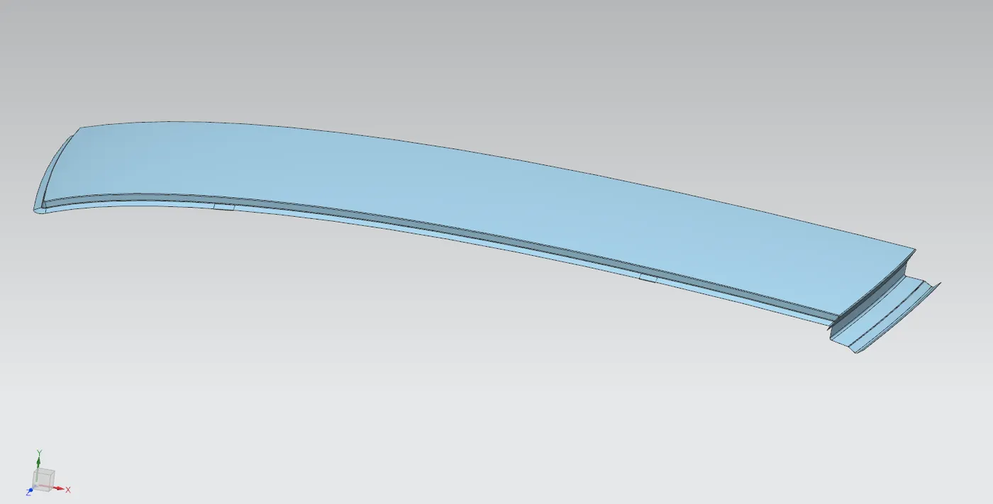
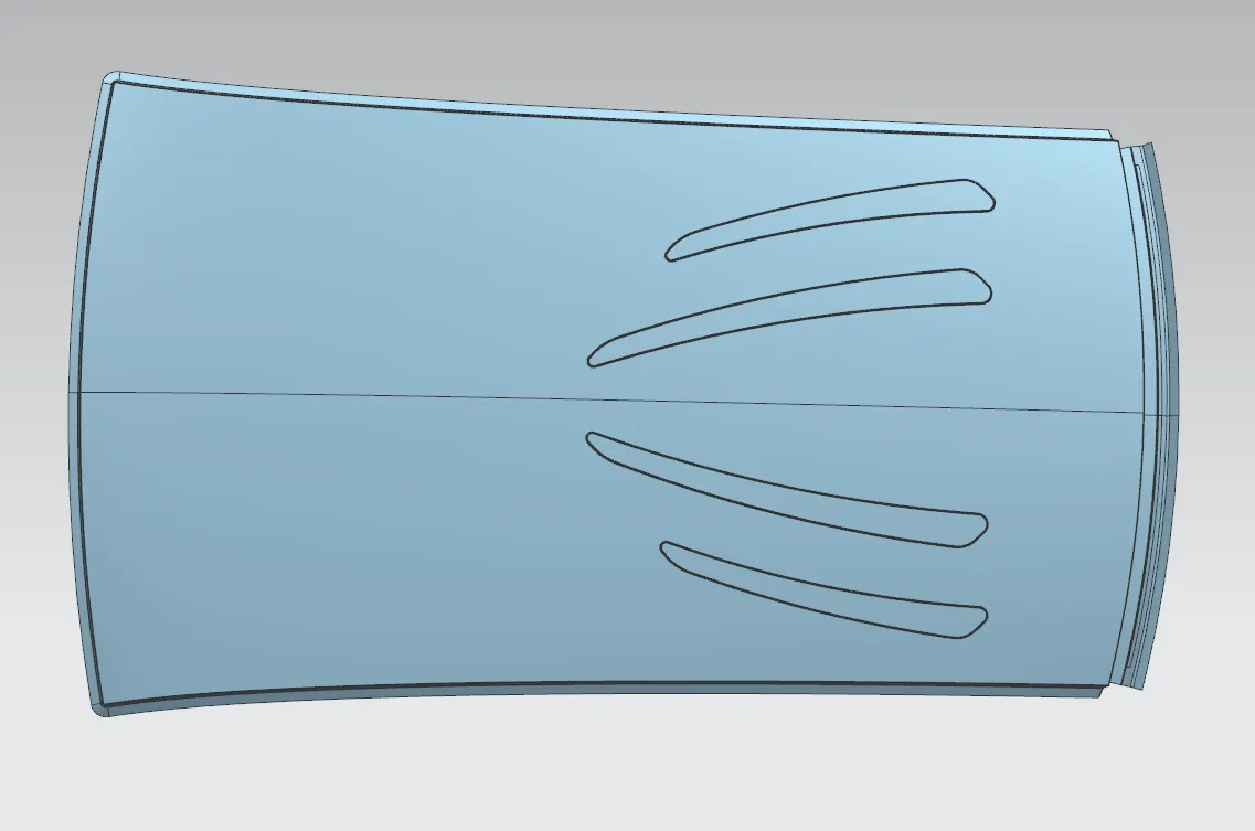
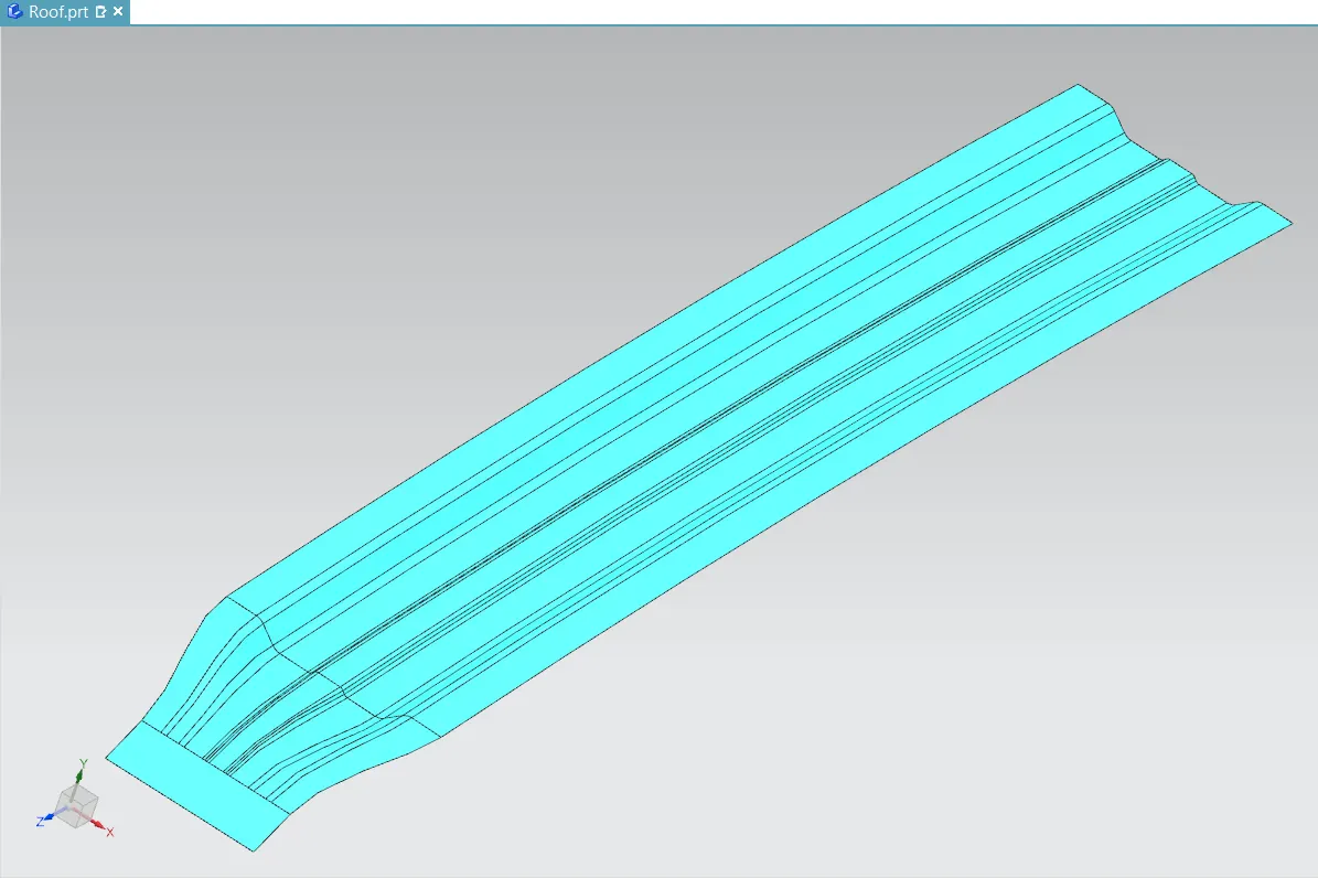
Step 1 : For creating the outer roof open the input surface and then create flanges according to the master section. Then it is mirrored and some embosses are created for providing extra strength and then it is thickened.
- We are adding the flanges to all sides of the roof for spot welding of the front roof rail, central roof rail, rear roof rail, and bows.
- The length and angle of the flange are decided based on the visibility criteria and according to the draw angle required for manufacturing the sheet metal.
- The thickness of the roof is decided 0.75mm
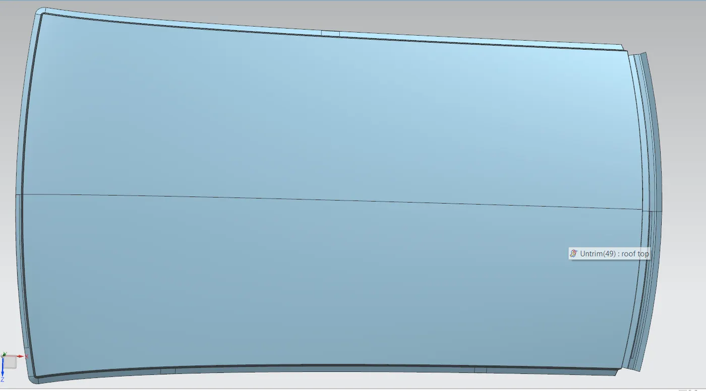
After creating emboss
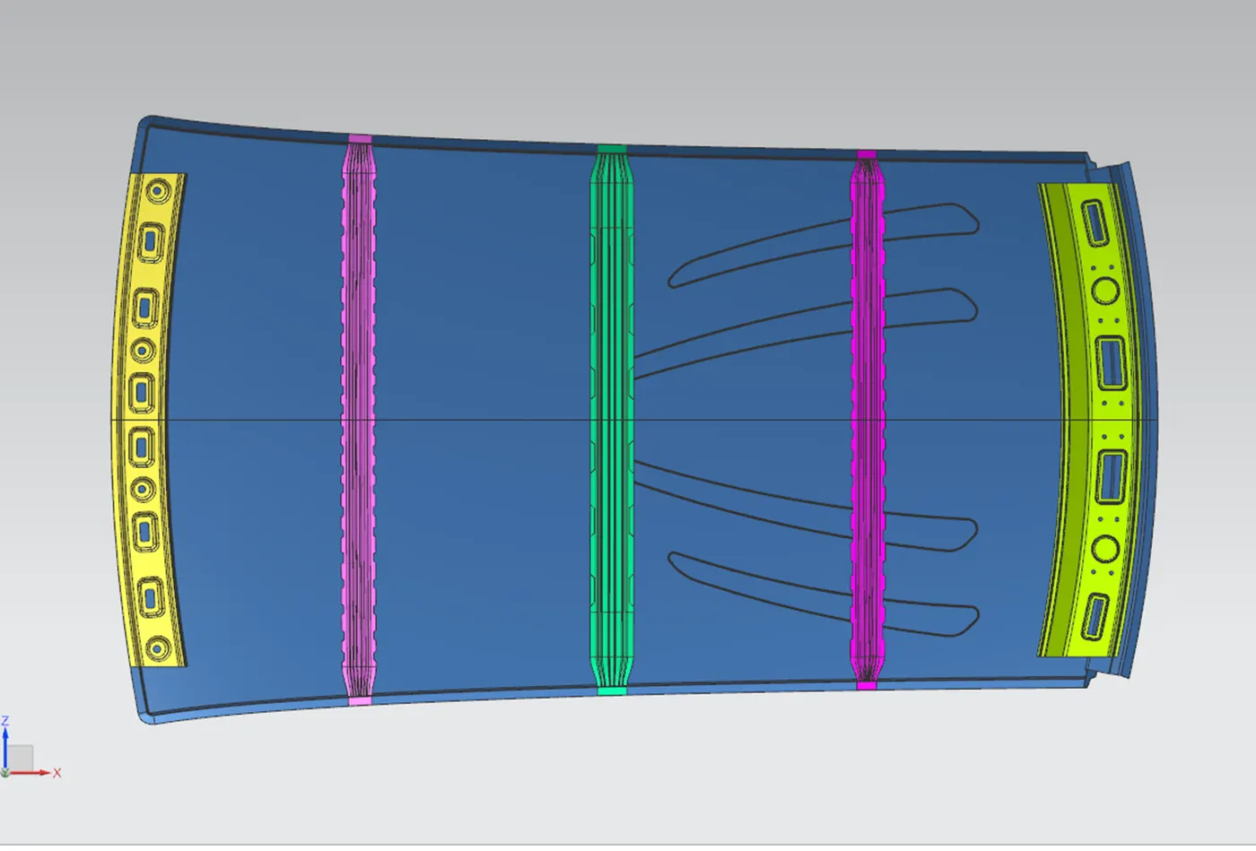
Step 2 : Extract the required portion, first the front roof rail is created refering the master section.Then after creating one half it is mirrored and then thickened.
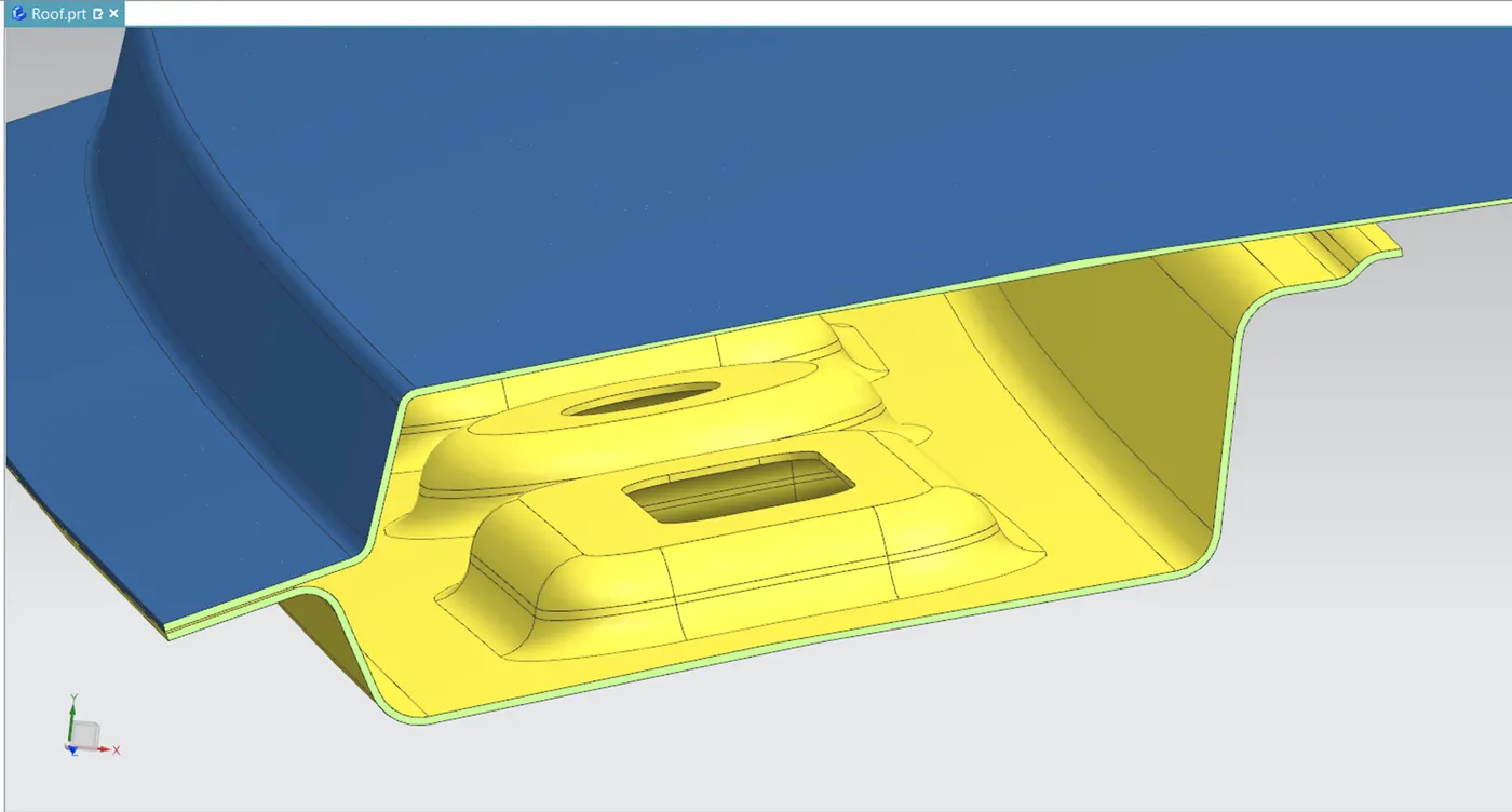
- The front roof rail is used as the reinforcement to the roof surface to increase the strength and also used to mount the brackets for some features such as room lamp or map lamp and rear mirror.
- The depth of the front roof rail is decided based on the visibility criteria line decided for the driver visibility.
- The width of the front roof rail is decided in such a way that there should be enough headroom clearance between the head of the driver and the end surface of the roof rail to avoid injuries to the person.
- At the front side we are doing spot welding and on the rear side of the front roof rail, we are using mastic points to join it with the roof surface.
- The minimum radius for the fillet at edges is 3mm
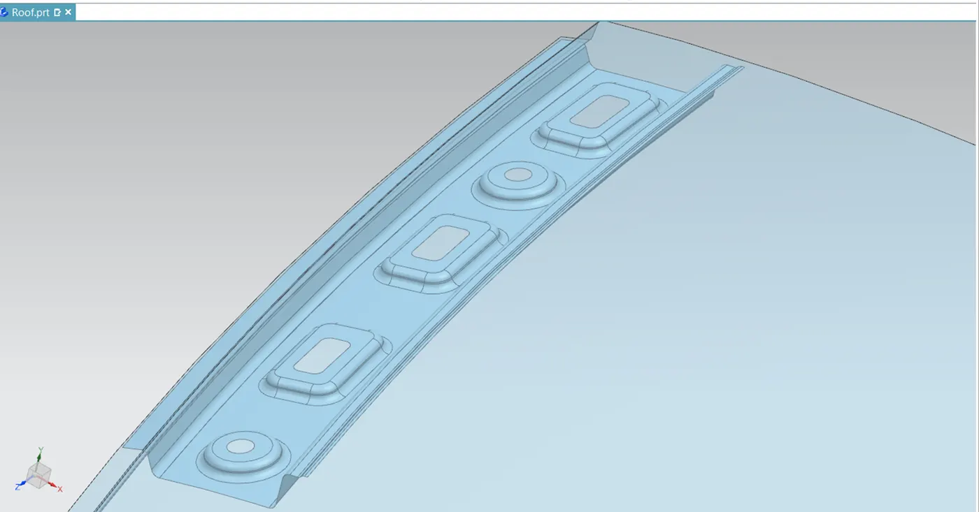
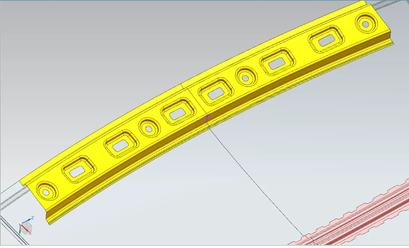
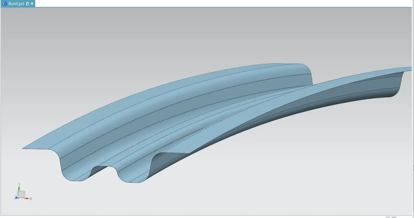
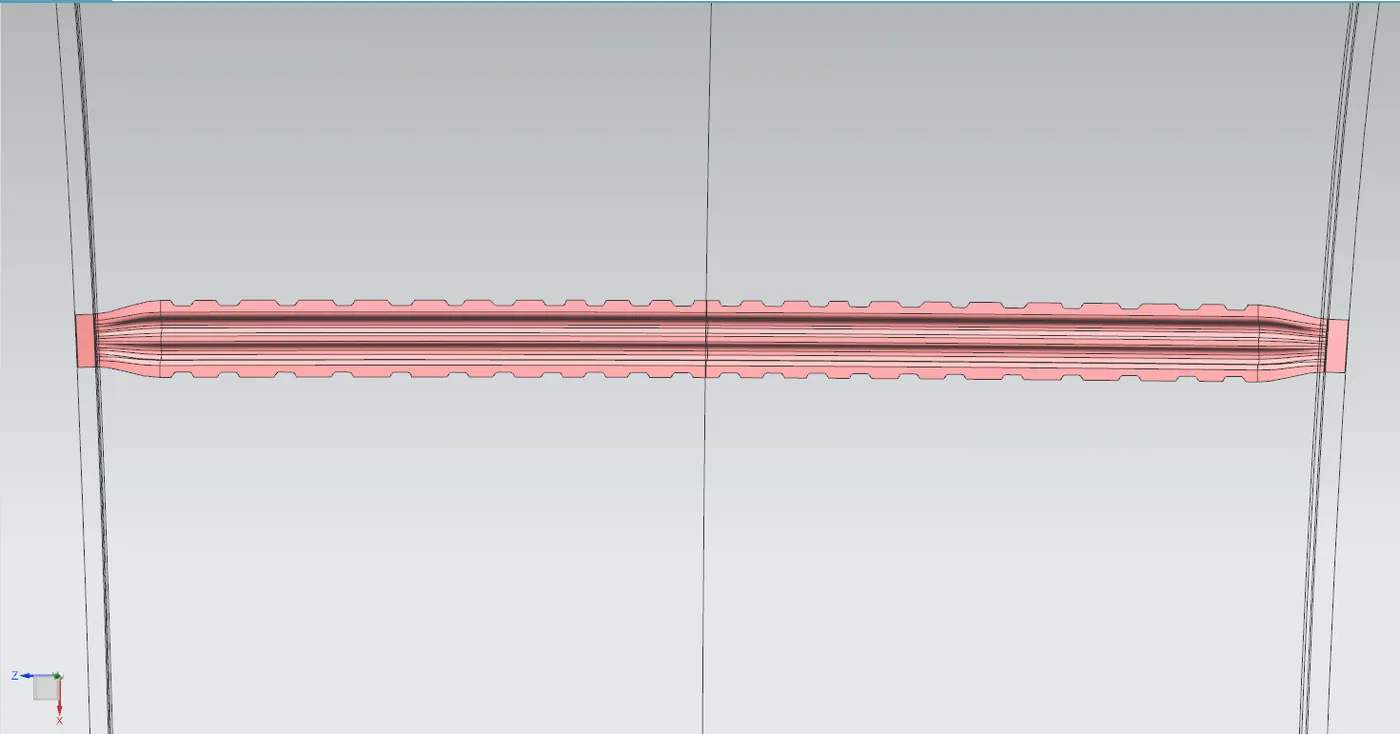
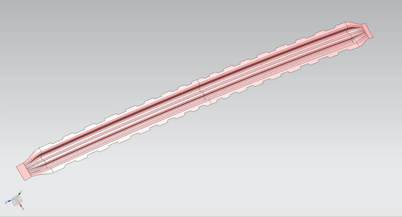
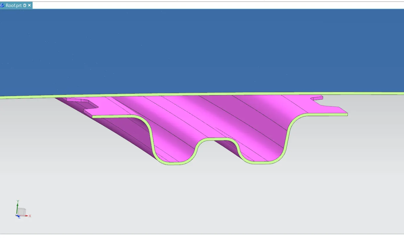
Step 2 : Next we are going to create the bow roof 1 as per the master section same as following the steps in creating front roof rail.Mastic points are also created inorder to join with the roof top surface.It is then mirrored and thickened.
- Both ends of the bow are joined to the roof outer flanges by the spot welding and the inner sides of the bow are joined to the inner surface of the roof with the help of mastic points.
- The minimum radius of the fillet is 3mm.
- The cross-section of the bow is made in such a way that we should get the maximum value of the minimum moment of inertia at which the bow fails.
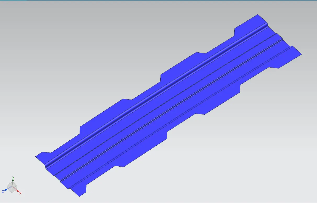
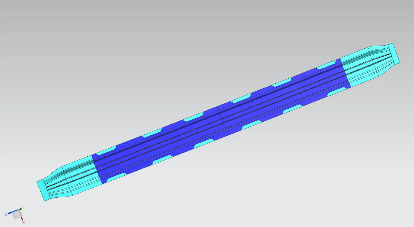
Step 3 : Next the Center roof rail is created by referring the master section.The center roof rail is joined to the outer roof using spot welding at the flanges.
Also inordet to give extra strenght to the center roof rail it is reinfornced with reinforcement roof rail.
After creating the half of both roof it is mirrored and thickend.
The reinforcement roof rail is also created referring the master section and it is joined with the center roof rail using spot welding.
The reinforcement roof rail is joined to the roof using mastic.
Center roof rail inner roof:
Center roof rail Reinforcement :
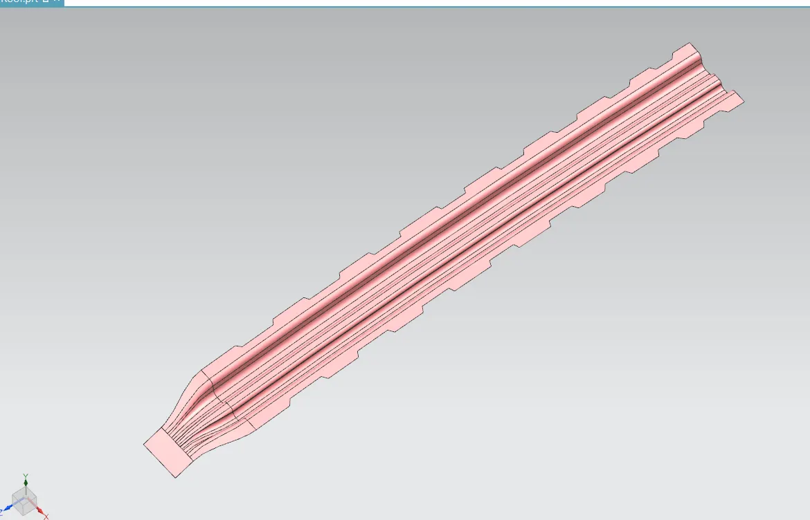
Step 4 : Next the bow roof 2 is created after the center roof rail. This is done similarly as the bow roof 1 with mastic points to join with the roof top.After creating the one half it then mirrored and thickened.
Step 5 : Next the rear roof rail is created using the master section, it is then mirrored and thickened. 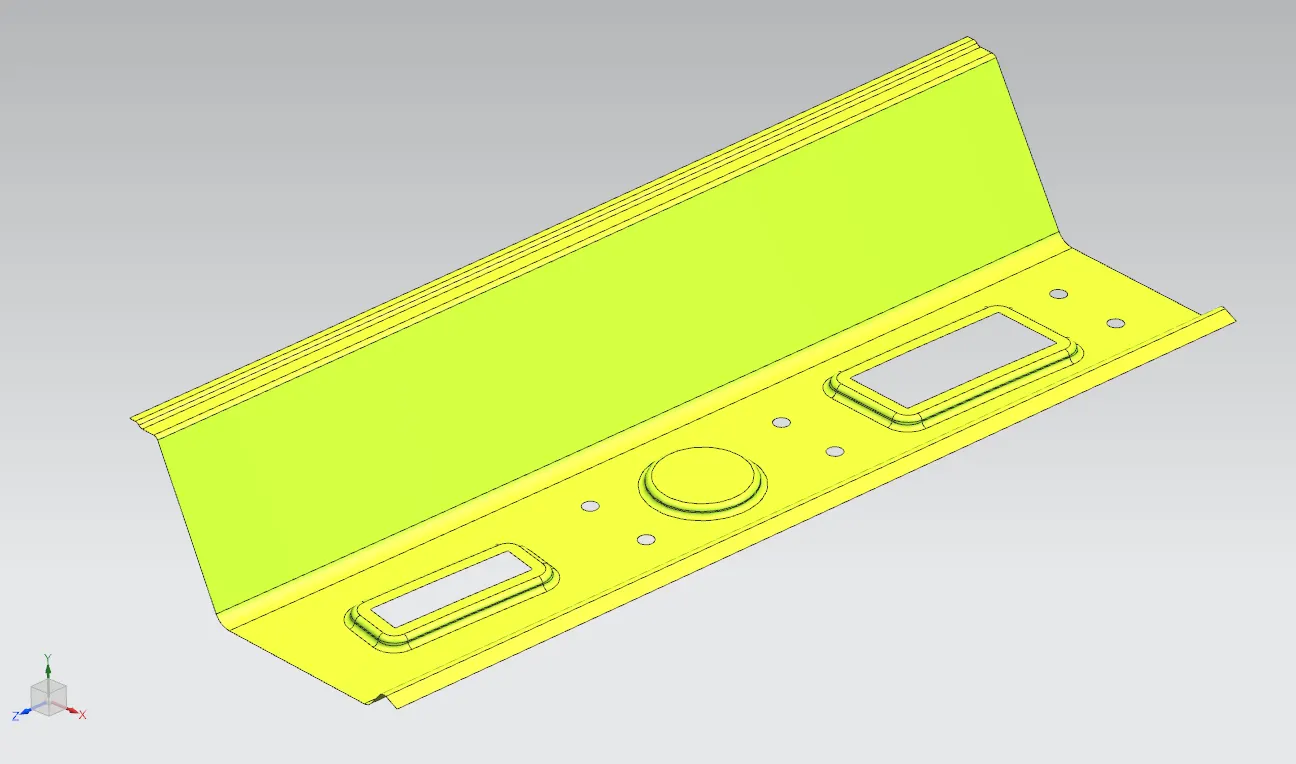
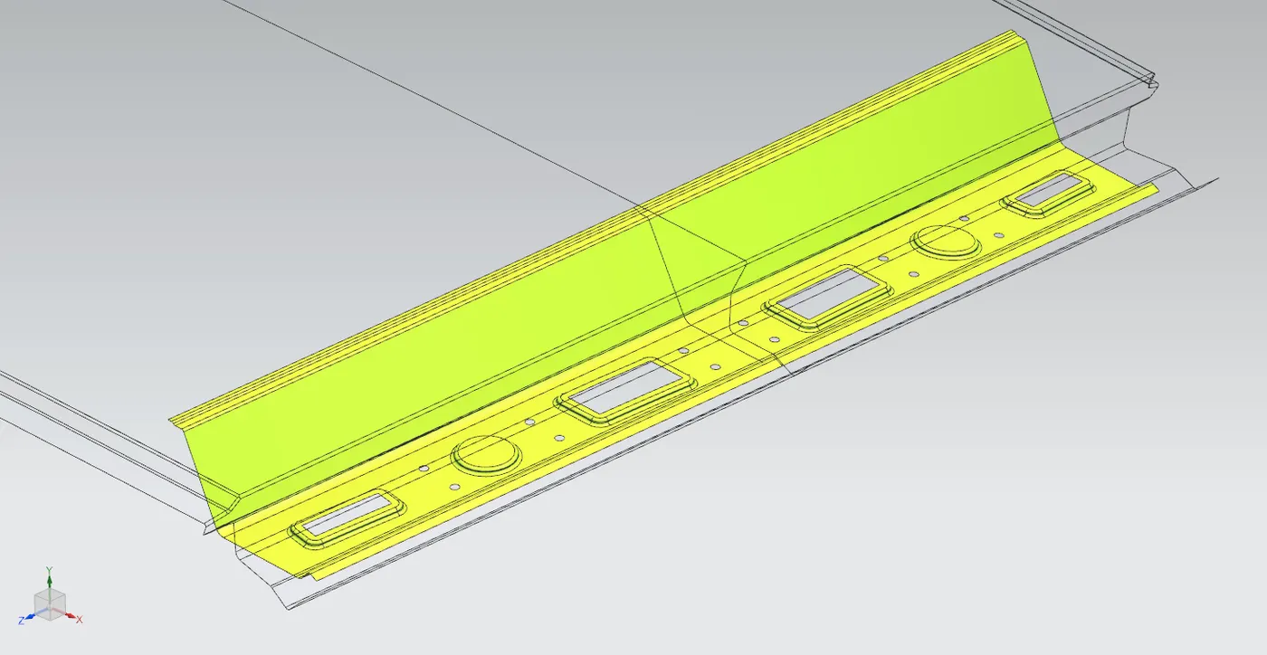
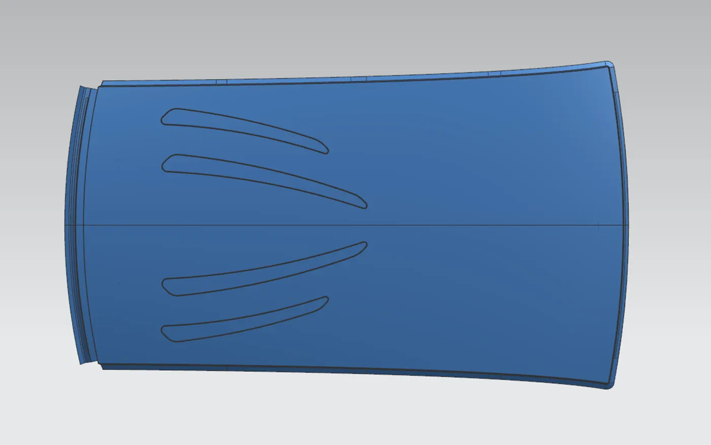
Final View
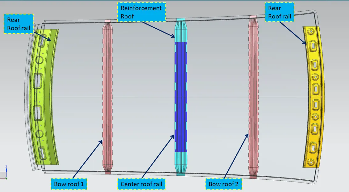
Top View
Bottom View
Sectional View of Front roof rail
Sectional View of bow roof 1
Sectional View of Front roof
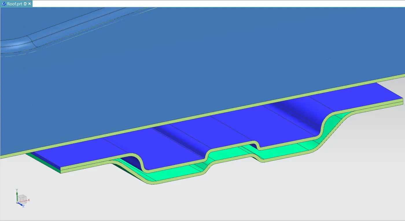
Sectional View of Center roof rail with reinforcement
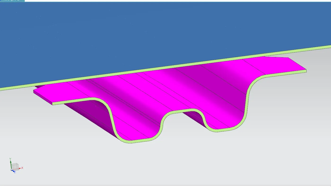
Sectional View of Rear roof rail
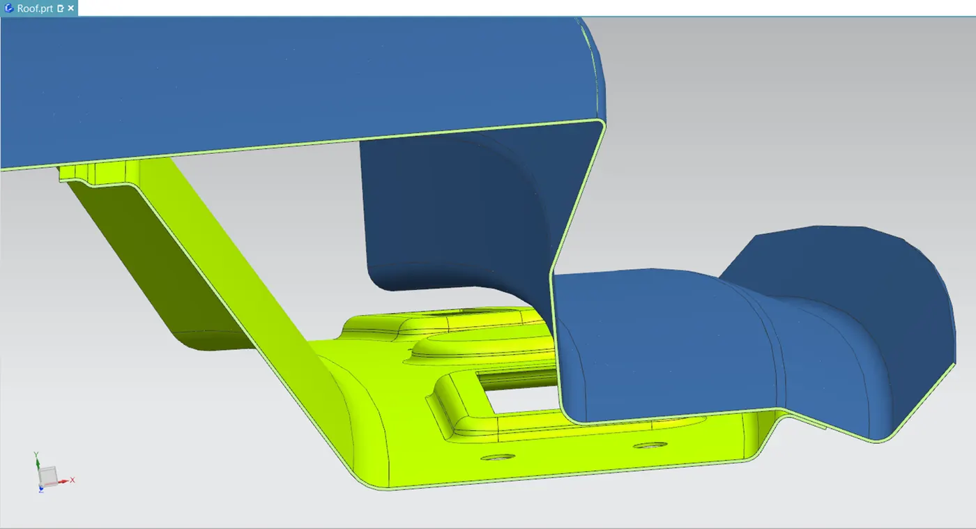
Heat distortion criteria - Bow–Roof Prediction Formula
In this criteria, we check the heat distortion capacity of the roof at higher temperatures with the fixed load on it. So when the surrounding temperature is high and the roof is loaded with some weight on it then if the roof is deformed it fails, so to calculate whether the roof deform or not, according to the position of the bow we do these calculations as follows
The formula for the heat distortion criteria:
Steps to calculate the Heat distortions as follows:
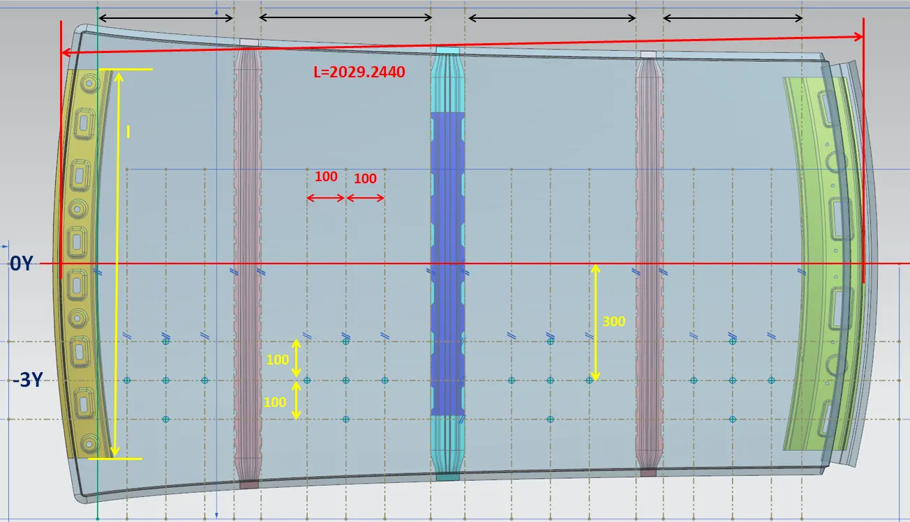
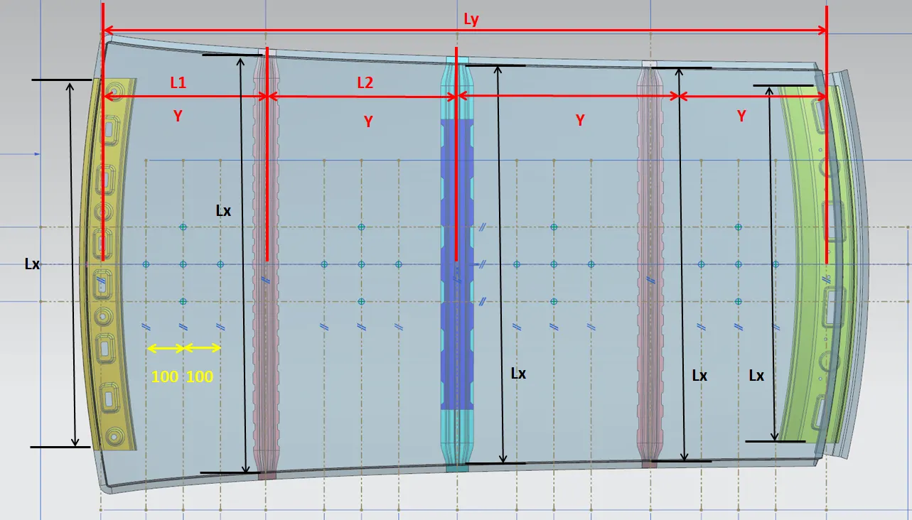
1.First we offset the center y-axis line to 300mm distance apart from it represented as (-3Y to 3Y red line).
2.After that we offset this -3Y to 3Y to 100mm offset each side represented with the green line.
3.We draw the vertical red line at the center of the two consecutive bow rood span. Next, we offset this red line to 100 on each side.
4. Now we have three horizontal lines and 12 vertical lines we take the intersection points of the vertical red line with three horizontal lines and a horizontal red line we take the intersection of the vertical lines with that line.
5.After getting all the points we project these points on the roof surface and draw the three points curve along the x-axis point to get the radius of curvature of Ry and along y-axis points to get the radius of curvature of Rx.
Calculations :
W = [1.73 x 10^(-3) x L] + [1.85 x 10^(-8) x (R^2)/t] + [ 1.10x10^(-3) x l] - 2.68
Where,
L = Roof Length in X-Direction[mm](Roof dimension in 0-Y)
R = Roof curvature
R = 2(Rx*Ry)/(Rx+Ry)
Rx = X curvature
Ry = Y curvature
t = Roof plate thickness [mm]
l = Bow Roof Span [mm]
Front roof rail
L = 2029.244 mm
t = 0.75 mm
I = 354 mm
`R_x` = 5741.2224 mm
`R_y` = 2422.0246 mm
R = `2((5741.2224 *2422.0246)/(5741.2224 +2422.0246))`
= 3406.826202 mm
W = [1.73 x 10^(-3) x L] + [1.85 x 10^(-8) x (R^2)/t] + [ 1.10x10^(-3) x l] - 2.68
= [1.73 x 10^(-3) x 2029.244] + [1.85 x 10^(-8) x (3406.826202^2)/0.75] + [ 1.10x10^(-3) x 354] - 2.68
= 1.51
The condition for the heat distortion criteria is W<2.7 .Here the W is 1.51, which is less than 2.7 so the position of the bow 1 is correct according to the hear distortion criteria.
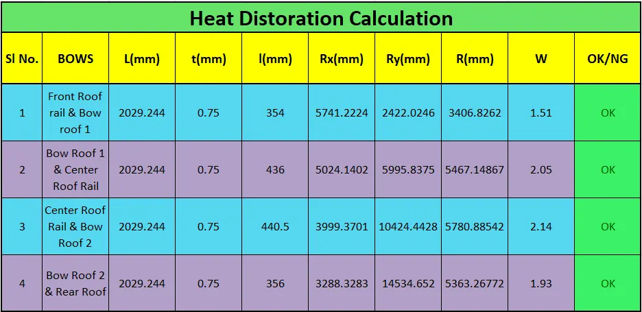
Similarly the calculation for remaining roof rails are calculated and tabulated:
Snow load predicition
This snow load condition calculation is done to check the strength of the roof when there is dead weight on the roof. As we know that in some regions we have snowfalls so when snow falls on the roof then this act as dead weight because in some the rate of snowfall is more so the roof should sustain this dead weight for that we do this calculation to check the position of the bow and its sectional area.
The formula for snow load condition:
`Q_r = (I_y*t^2)/(alpha*s*[(R_x+R_y)/2]^2*10^(-8)`
1. Steps is same as heat distortion criteria but the difference is we calculate the Rx and Ry at the centerline of the roof along the y-axis
2.We have to calculate the moment of inertia of each reinforcement(Bow)
- We use the intersection curve command in NX software to get the sectional area of the bow along the XY plane.
- Now we project these curves on the other plane parallel to XY-plane at some offset distance.
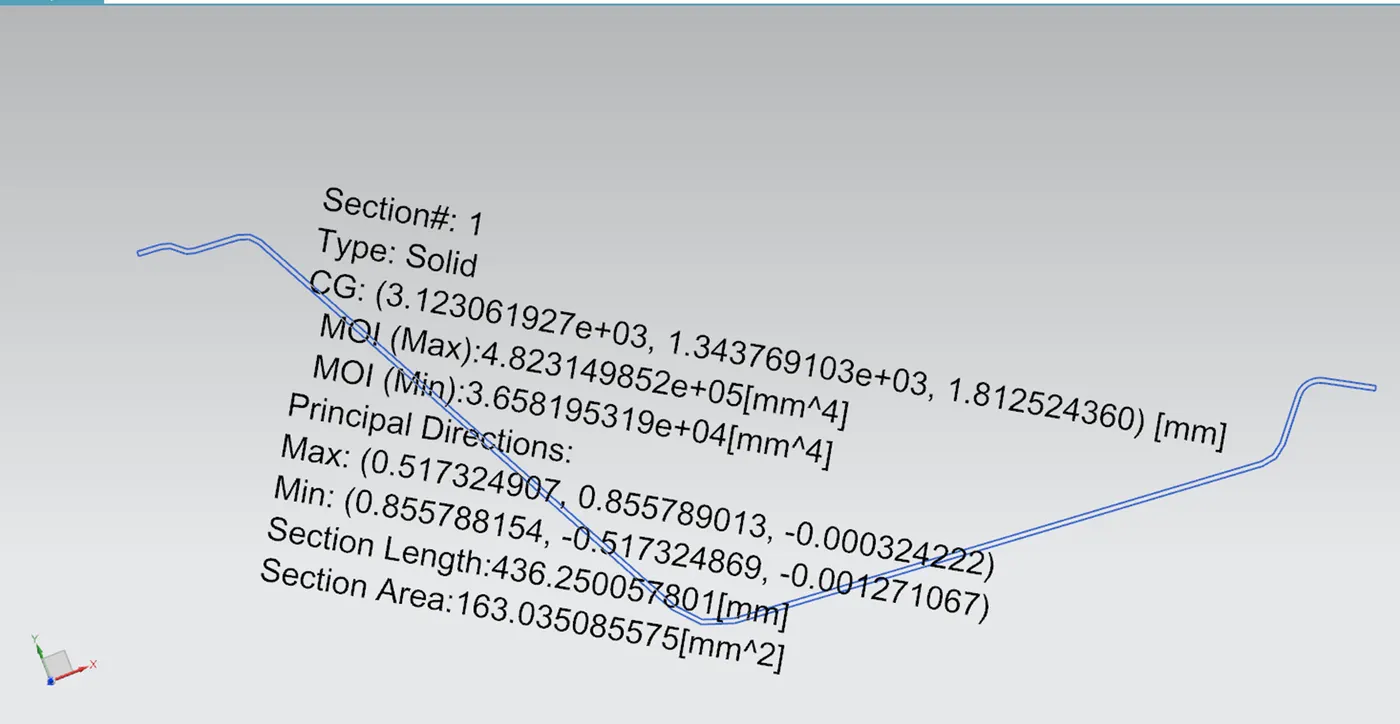
- Now we use a sectional inertia analysis tool to calculate the MOI as follows;
Moment of inerita of Bow Roof 1 :
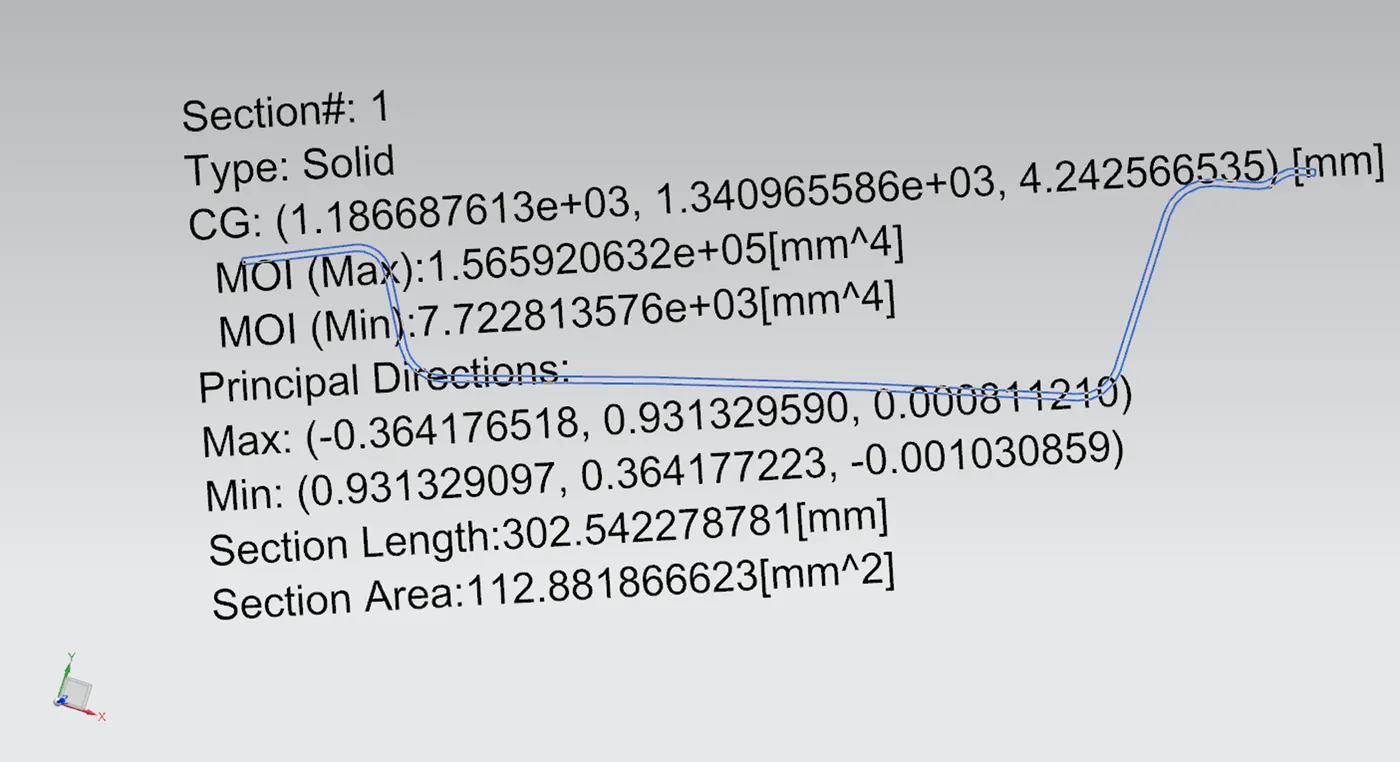
Moment of Inerita of Bow roof 1 :
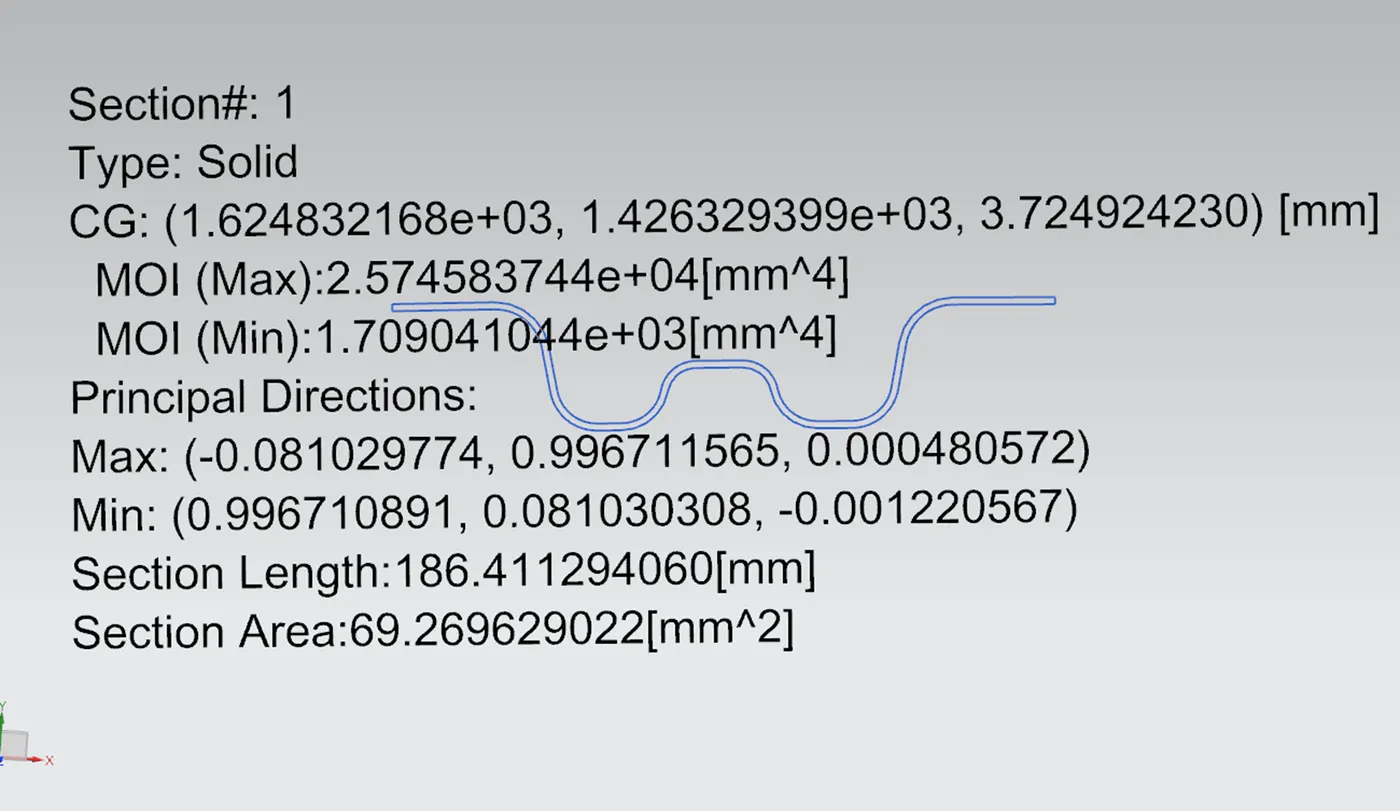
Moment of Inertia of center roof rail with reinforcement:
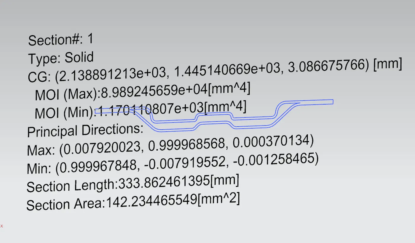
Moment of Inertia of Bow roof 2
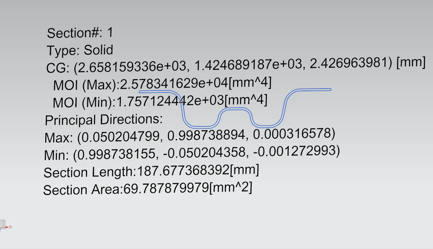
Moment of Inertia of Rear roof rail
Calculation:
For front roof rail and Bow1:
`I_y` = 156592 mm^4
Y = 443 mm
`M_y` = `Y(I_y -Y)`= 443 (156592 - 443)
= 667246.6
`L_x` = 999.9986 mm
`alpha`= `M_y*L_x^2*10^(-12)`
= 667246.6 * 999.9986^2 *10^(-12)
= 0.667244732
s = `(L_1)/2+(L_2)/2` = (443/2) + (514.7/2)
= 478.85
t = 0.75 mm
`R_x` = 4662.8971 mm
`R_y` = 2420.9947 mm
`Q_r = (156592*0.75^2)/(0.667244732*478.85*[(4662.8971+2420.9947)/2]^2*10^(-8)`
= 2197.47
Judgemental criteria is Qr > 3.1
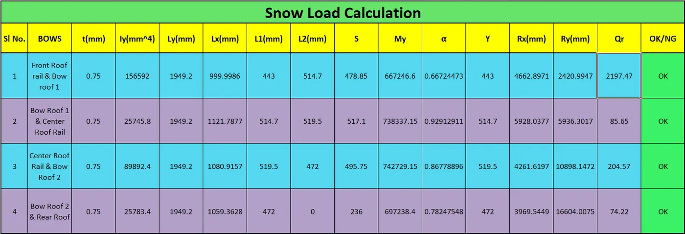
Here the front roof rail and Bow1 the Qr is 2197.47 which is grater than 3.1 so for it passed the snow load condition and the position of Bow1 is correct.
The calculation for the remaining Bows positions are done and tabulated,
Draft analysis
Roof Top
Front roof Rail
Bow roof 1
Center roof rail
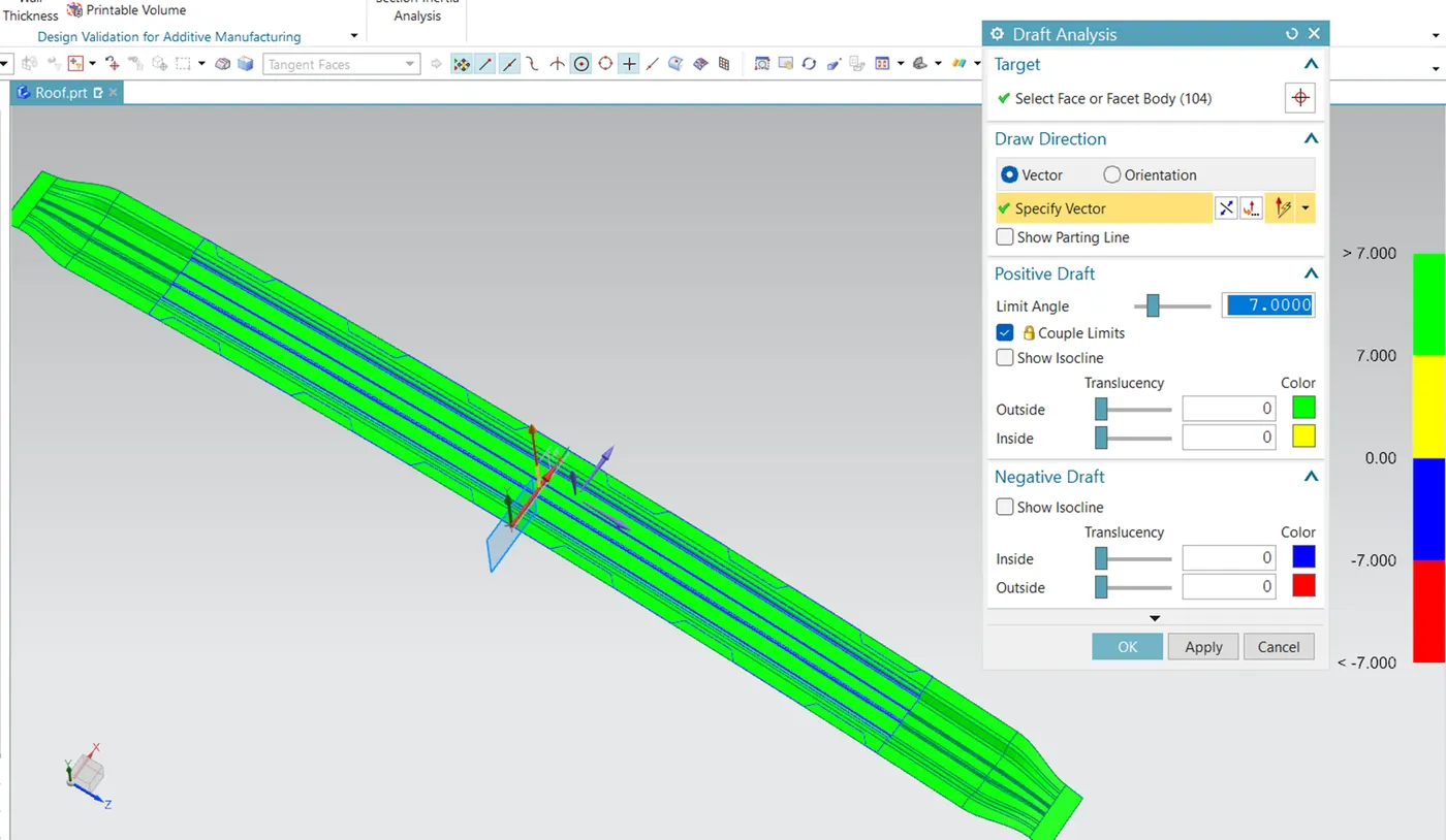
Bow roof 2
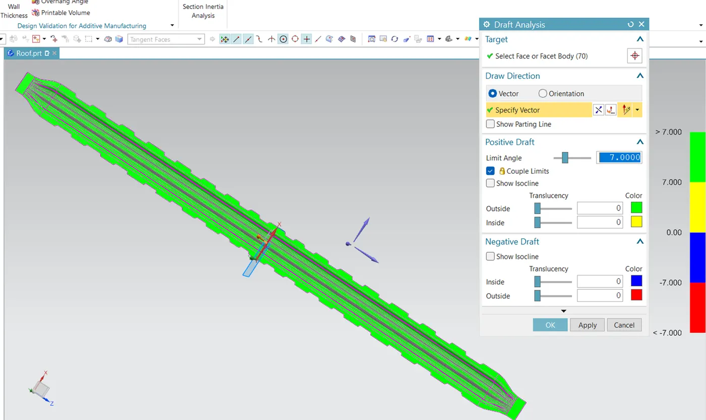
Rear roof rail
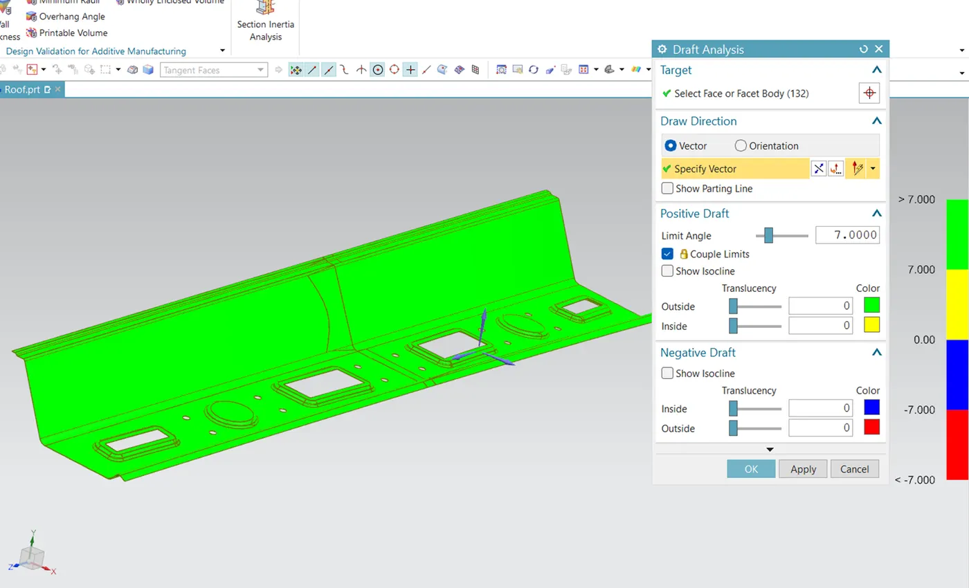
CONCLUSION
- Created an assembly for a given roof styling by developing the essential flanges for the outer roof and creating the reinforcements.
- Conducted draft analysis for ensuring the part clear draft.
- Calculated the Heat distortion, Snow load and section inertia on roof.