Structural Modelling using Etabs 2018
AIM:
- To conceptualize a framing plan layout and then model the building in Etabs.
- To design the structural model in compliance with provisions of IS 1893 and IS 13920.
- To run a modal response spectrum analysis and check analysis results of the etabs model for inter-storey drift requirements, vertical & planar irregularities, minimum shear wall requirements,maximum axial load ratio for column and shear walls, effective moment of inertia for beams and columns etc.
PROCEDURE:
STEP 1:
- Open the Etabs software.
- In the Start page select New model option.
- In the dialogue box that appears select the Use built in settings option.
- Change all the fields as required.
- Click on OK.
STEP 2:
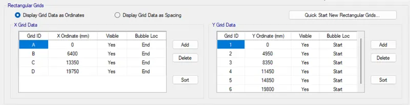
- In the dialogue box select Custom Grid spacing-> Edit Grid data.
- As per the specifications provide Grid data.
- Click on OK.
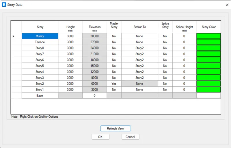
- In the dialogue box select Custom Story data-> Edit Story data.
- As per the specifications provide the height and elevations.
- Rename the stories as necessary.
- Set the Story 1 as master story.
- Set the other stories as Similiar to the Master story.
STEP 3:
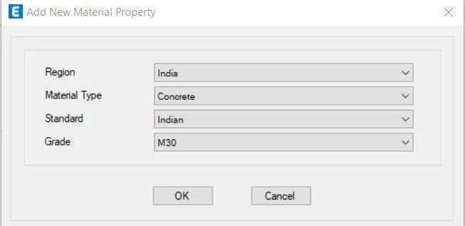
- To create the concrete material.
- Select Define-> Section Properties-> Frame sections.
- In the Define material dialogue box select Add new material option.
- Fill in the required fields as the following.
- Click on OK
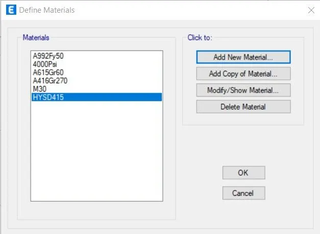
- Follow the same procedure to create rebar material.
- The required materials have been created.
STEP 4:
- To create the beams.
- Select Define-> Section Properties-> Frame sections.
- In the Define material dialogue box select Add new material option.
- Select Concrete rectangular option.
- Modify its properties as required.
STEP 5:
- To create the columns.
- Select Define-> Section Properties-> Frame sections.
- In the Define material dialogue box select Add new material option.
- Select Concrete rectangular option.
- Select the Modify/ Show rebar option.
- Modify its properties as shown below to create the columns
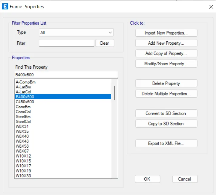
Beams and Columns are defined.
STEP 6:
- To create the shear walls.
- Select Define-> Section Properties-> Wall sections.
- In the Define material dialogue box select Add new material option.
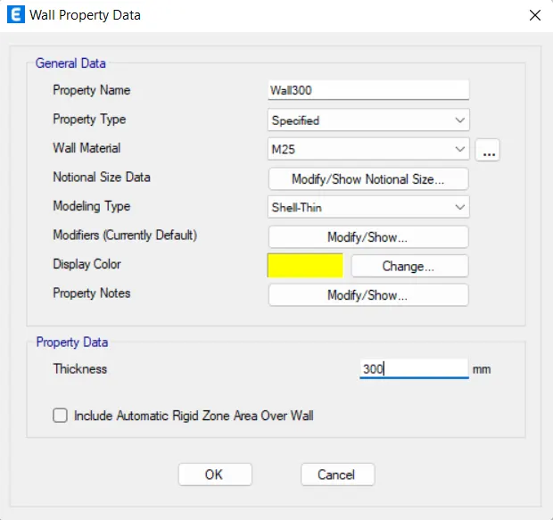
- Provide required properties as shown below to create the shear walls.
STEP 7:
- Select Define-> Load patterns.
- Add the following Load patterns.
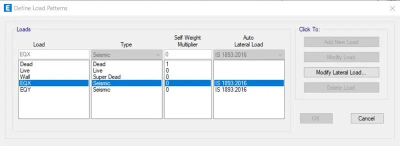
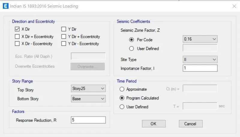
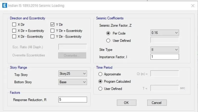
- For the loads EQX and EQY select Modify Lateral load.
- In Direction and Eccentricity panel check only X dir for EQX and uncheck the other boxes.
- Select only Y dir and unchech other boxes for EQY.
- Click on OK.
STEP 8:
- Select Define-> Mass Source.
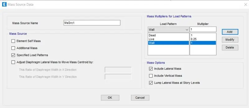
- In the dialogue box that appears select Modify Mass source.
- In Mass source panel select specified load patterns and unselect others.
- Add the Load patterns and their multipliers as per Code as shown below.
- CLick on OK.
STEP 9:
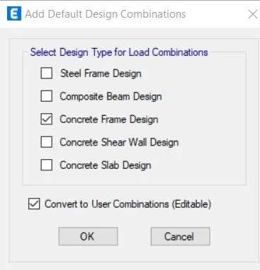
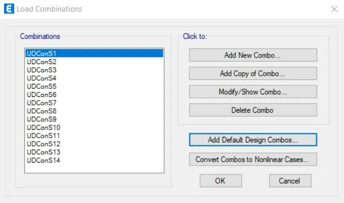
- To add load combinations select Define-> Load combinations-> Add default design combos.
- Check the Concrete Frame design box .
- Check the Convert to user combinaations box.
- Click on OK
- The Load combinations have been generated.
- Click on OK.
STEP 10:
MODELLING:
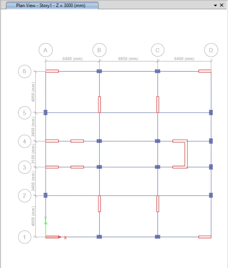
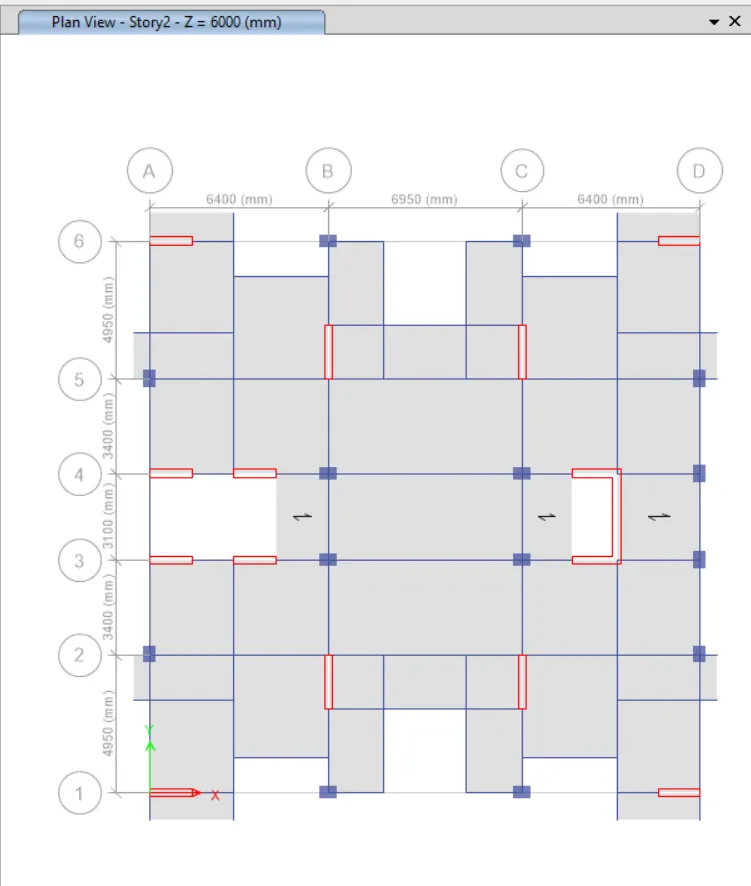
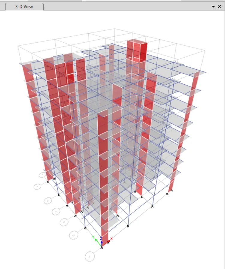
- Using Quick Draw columns, Quick Draw beams, Quick Draw Floors icon columns, beams and slabs will be drawn.
- In the Properties of object window change the Property to the appropriate one.
- Set the Working plane as All stories.
- Model the Properties as required.
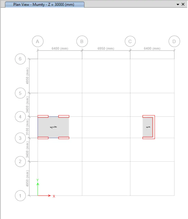
- Place the Shear walls and then edit the Grid as per the Floor plan.
- Edit the Model as per required for the Parking floor and mumty level.
STEP 11:
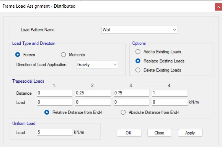
- To assign loads to the frames go to Select-> Properties-> Frame sections.
- Select the created Beams.
- Go to Assign-> Frame loads-> Distributed
- Change the required fields as shown below.
- Click on APPLY and OK.
- To assign loads to the slabs go to Select-> Properties-> Slab sections.
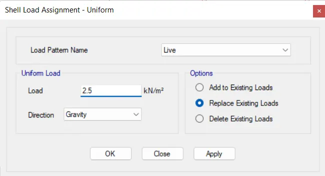
- Select the created slabs.
- Go to Assign-> Shell loads-> Uniform
- Change the required fields as shown below.
- Click on APPLY and OK
STEP 12:
- To assign diaphragm selet Assign-> Shell-> Diaphragms-> D1.
- Click on APPLY and OK.
- The centre of mass is now automatically calculated.
STEP 13:
- Click on Run analysis icon.
- Once the analysis is complete click on Save icon to save the file.
ANALYSIS RESULTS:
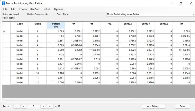
Modal mass participation for first 3 modes dominates atleast 65% in both X and Y axis - Achieved
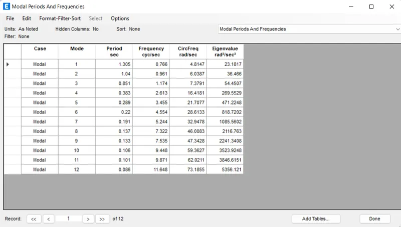
Mode 1 and 2 differ by 10% minimum - Achieved
Principal Modes greater than Torsion mode - Achieved
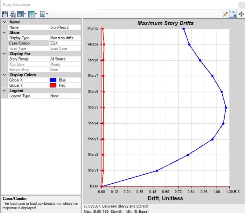
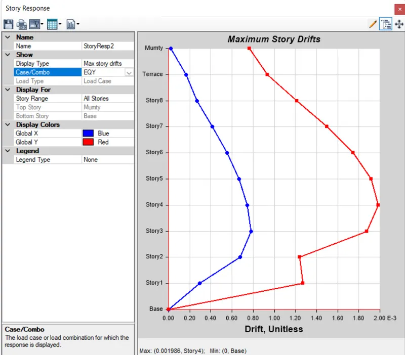
Inter Storey drift ratio less than 0.004 - Achieved
Base shear share between column and shear walls- Not dual system
Axial stress in column and shear wall - Achieved.