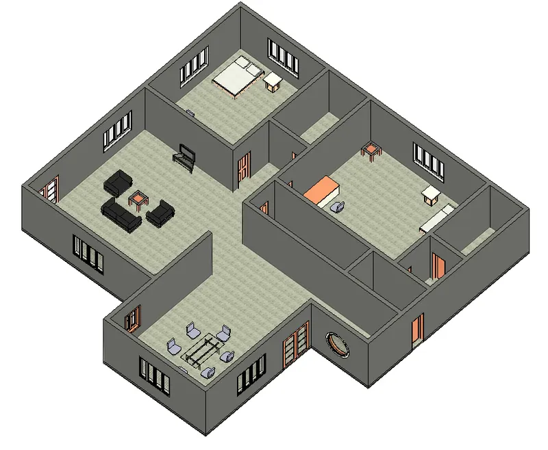
Creating Levels, Grids, Layout and model elements for a residential unit using REVIT
1) Building Information Modeling (BIM):
It is the holistic process of creating and managing information for a built asset. Based on an intelligent model and enabled by a cloud platform, BIM integrates structured, multi-disciplinary data to produce a digital representation of an asset across its lifecycle, from planning and design to construction and operations.
Features of BIM:
- Easy acces to information.
- Making process more expressive: Length, breadth, depth, time and cost of a project.
- Comprehensive view of the project.
Benefits of BIM:
- Complete representation
- Instant updates
- Time constraint
- Resource tracking.
2) Revit offers a huge database of components that allows the addition of details to a project. These elements can be interpreted as a hierarchy which is as follows:
CATEGORY:
It controls the organization, visibility, graphical representation and scheduling options of families within the project.
FAMILY:
It is a group of 2D or 3D information that serves to represent a discreet building or documentation element in a project. It defines parametrical, graphical and documental requirement.
TYPE:
Specific representation in a famliy defined by distinct parameteical, graphical and documental characteristic which makes it unique from other types in a famliy.
INSTANCE:
Individual representation of a type in the project defined by unique parametric, grapical and documental characteristics which make it unique from other instances in a Type.
PROCEDURE:
- In the Ribbon Click on Insert Tab -> Load Family.
- The following dialogue box appears.
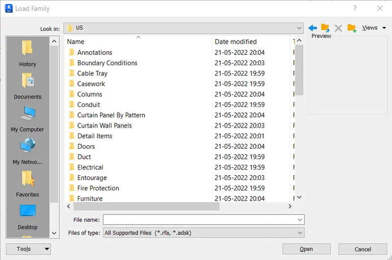
- Select the required family and it gives a variety of Types to choose from.
- Each type has instances which can be chosen from the Property browser.
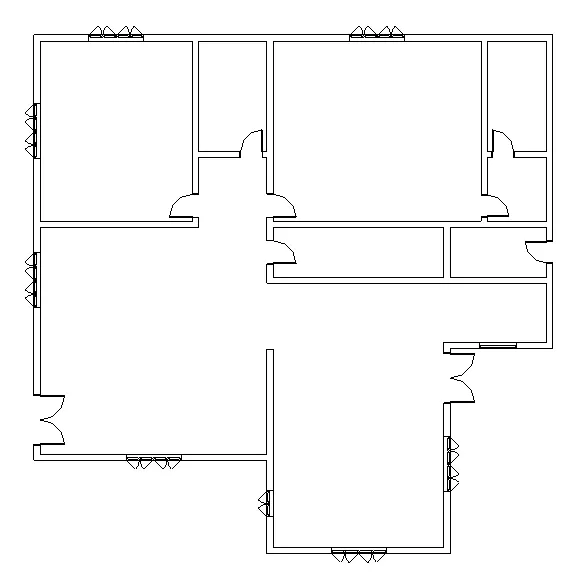
- In the mentioned process doors and windows are selected and placed in the model.
FINAL RESULT:
3)
AIM:
- To open a Project file with Architectural template.
- Save the file with appropriate name and set units to imperial.
- Complete project information from Manage tab.
- Set three Backups for the Project file.
PROCEDURE:
- In Revit click File -> New -> Project.
- In the New project dialogue box select Architectural template.
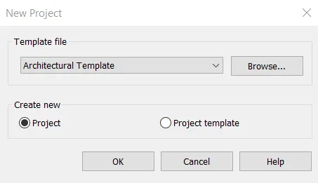
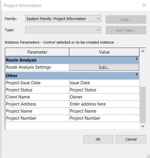
- To give the project information click on Manage tab and open Project information from ribbon.
- In the dialogue box select the details and edit them as required and click on OK.
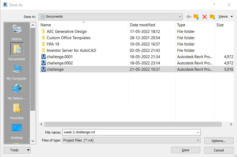
- To save the file click on File-> Save as.
- In File name type the required File name.
- Then click on Save to save the project.
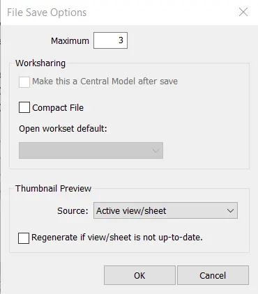
- CLick on Options button to open following dialogue box.
- In the dialogue box select Maximum backups as required and click on OK
FINAL RESULT:
A new project is opened with Architectural template, Project information is given and Saved with three backups.
4) LEVELS:
A level is a finite horizontal plane which acts as a reference for roofs. floors and ceilings inn the section and elevation views.
GRIDS:
A grid is a finite lines used to divide the project into smaller cells or units, they are used for locating and placing elements within a project with ease.
AIM:
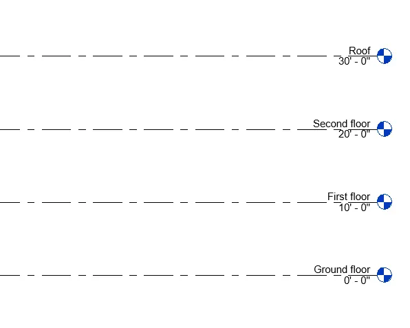
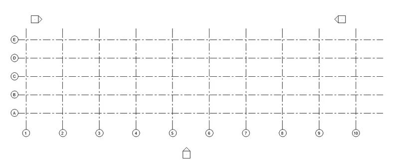
- To create the following levels: Ground Floor @ 0’; First Floor @ 10’; Second Floor @ 20’ and Roof @ 30’.
- To create the following grids : Grids Transverse Grids A, B,C,D, E @ 10’ spacing; Longitudinal Grids from 1 to 10 @ 20’ spacing.
PROCEDURE:
- In the Project browser Select Elevation and select East view.
- In the Datum panel of Architecture tab select Levels option.
- Then select Pick lines option and give offset as 10'.
- Offset the line by selecting the line to be offseted.
- Then Double click on the text to rename it as required.
- In the Project browser select Ground floor.
- In the Datum panel of Architecture tab select Grids option.
- The first of transverse and longitudinal grids is drawn by using Line.
- They are then drawn by using Pick line, in Offset required spacing is provided.
FINAL RESULT:
The required Grids and Levels are created by following the naming conventions.
5)
AIM:
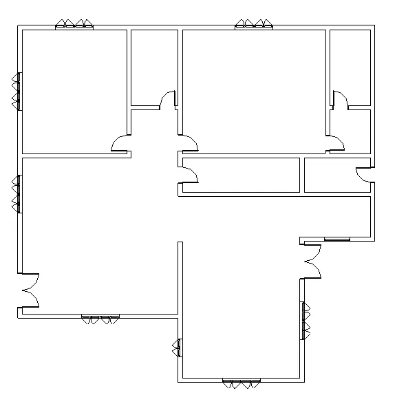
- To create a conceptual layout of a residential unit.
PROCEDURE:
- New project in Revit is opened with construction template.
- In Project browser select Floor plan -> Level 1.
- In the Architecture tab select wall to create layout of the model.
- The walls are created as per required dimensions.
- Then click on Architecture -> Doors -> Load family.
- The required doors and windows are selected and placed in the model.
- In the Project browser select Ground floor.
- In the Datum panel of Architecture tab select Grids option.
- The grids are drawn by using pick line option in Draw panel and walls are used as reference.
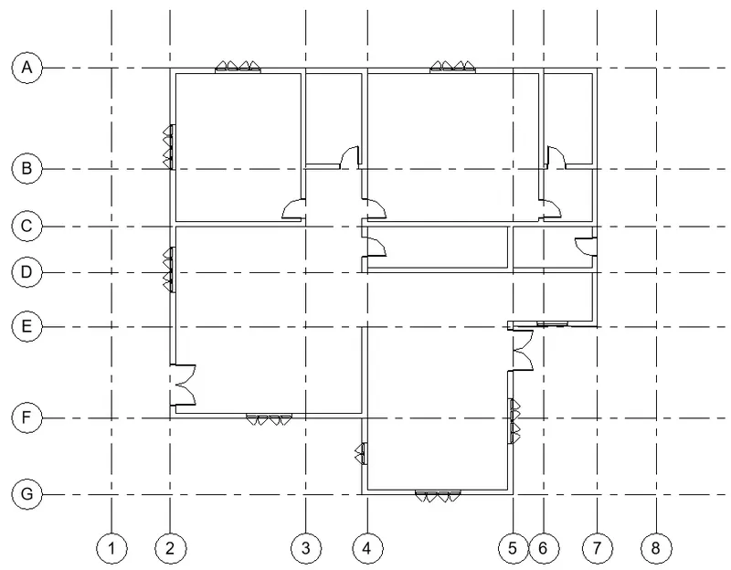
FINAL RESULT:
A conceptual layout of a residential unit is created using Revit.
6)
AIM:
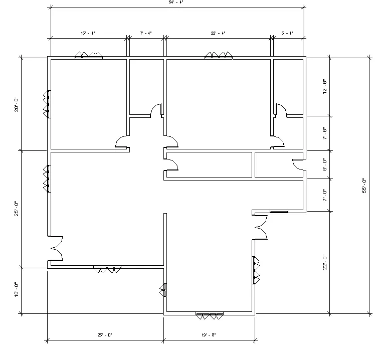
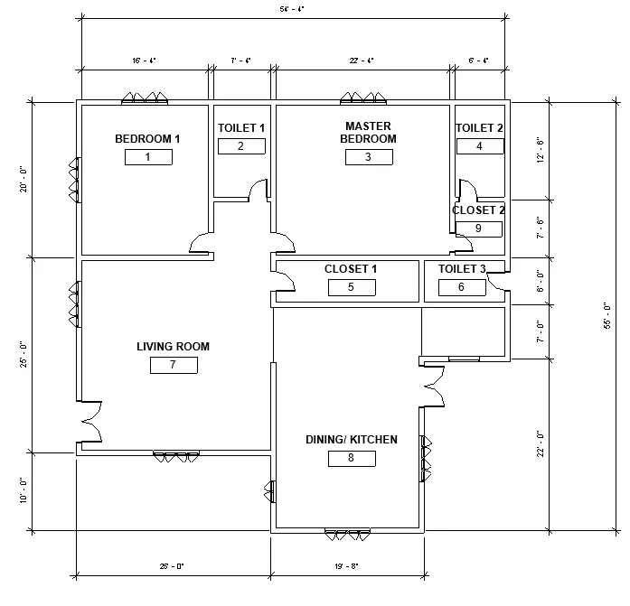
- To add dimensions of room and components in the layout created.
PROCEDURE:
- In the Annotate panel select Linear dimensions.
- Zoom in to the corner of the wall that needs to be dimensioned.
- Select the wall carefully and zoom out, select the next wall and extend the dimension line as required.
- Walls in Y axis are dimensioned in the same manner but by using Aligned dimensions option in Annotate panel.
- To create rooms seect Architecture-> Room.
- Revit detects boundaries of rooms and places tags where selected.
- Incase of Boundaries required to be given manuallly select Architecture-> Room seperator and draw the boundary.
- The rooms can be now detected as seperate.
FINAL RESULT:
Dimensions, rooms and components have been added to the created layout.
7)
AIM:
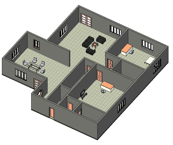
- To identify the residential model elements such as Door, Windows, Tables, Chair, Couch, Bed, Lamps from the library and insert them to the model .
PROCEDURE:
- Click on Architecture-> Component-> Place a component-> Load family.
- In the Load family dialogue box various families are displayed.
- Select the required family and choose the type of component that is required and it is placed in the model.
- In this manner all the required components and furniture are placed in the model.
- Any modifications to the components can be done in the Project browser.
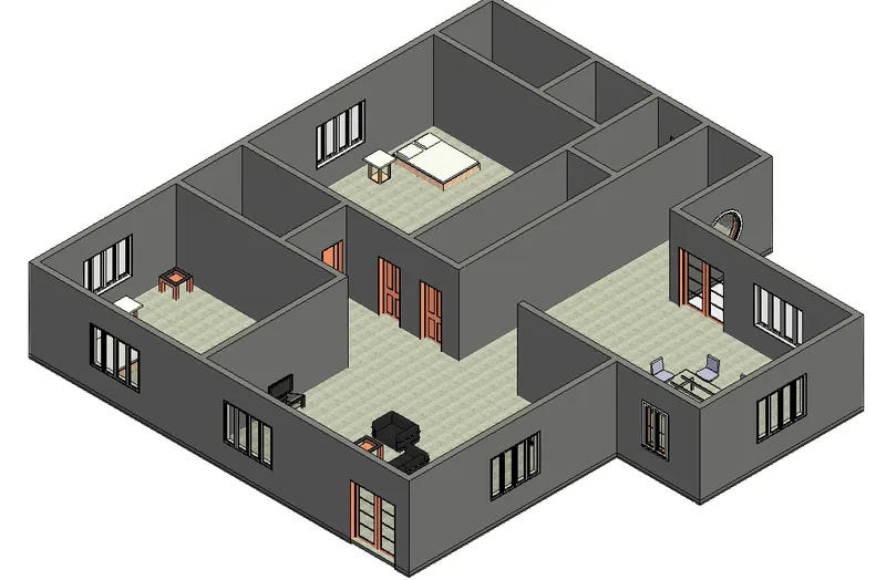
- The components can be editted using the tools from Modify tab.
FINAL RESULT:
Residential model elements such as Door, Windows, Tables, Chair, Couch, Bed, Lamps from the library are insertted into the model .