Creating Bar Bending schedule, Different Door types, and Creation of standard drawing templates using AutoCad
1) AIM:
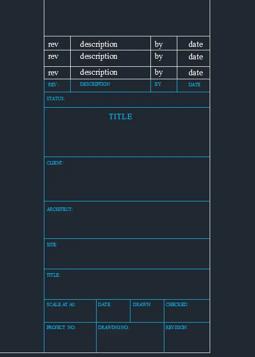
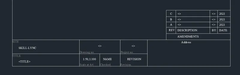
- To create the templates as shown in Figures.
- After creating the title block it must be saved as a block with names: Custom1_titleblock and Custom2_titleblock, respectively.
PROCEDURE:
- The Tables are drawn using LINE and OFFSET commands.
- The text is given using DTEXT command.
- It is editted using Manage text styles from the Annotate panel in the ribbon.
- The given text is Times New Roman.shx.
- The text is copied and pasted using COPY wherever necessary.
- It is then editted by double clicking it and typing required text.
- The colour of the lines and text is changed by selecting the required content and changing the colour from properties.
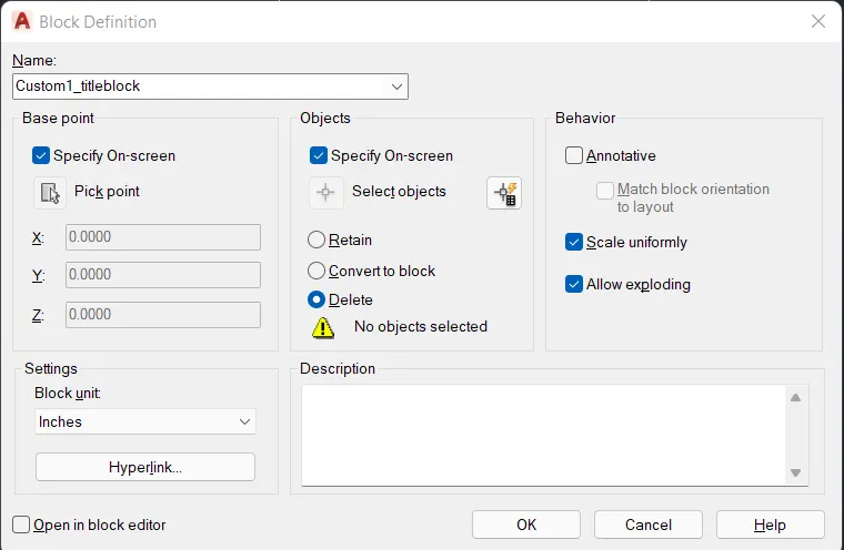
- It is then converted into a block using BLOCK command.
- The name is given as Custom1_titleblock.
- The same procedure is followed for the second template.
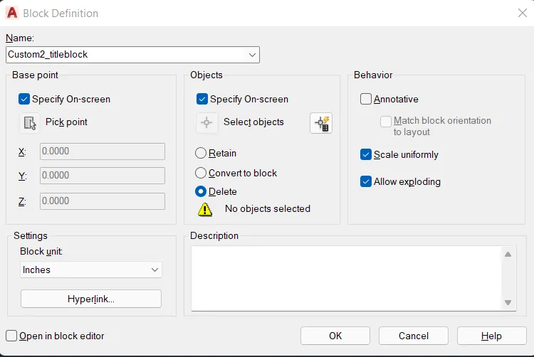
- The block is created using BLOCK command and name is given as Custom2_titleblock.
RESULT:
The required templates are created as shown in Figures. The title block is saved as a block with names: Custom1_titleblock and Custom2_titleblock, respectively.
2)
AIM:
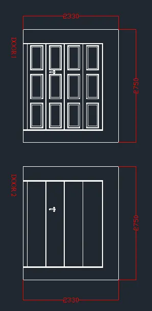
- To create the doors type for warehouse as shown in the Figure.
- To create the blocks of this door type after creating them.
INTRODUCTION:
- UNITS command is given and units are set to mm.
- Using RECTANGULAR command and dimensions the outline is created.
- Using PLINE command the inner rectangle is created.
- Within the door the smaller rectangles are created using LINE and OFFSET commands.
- It is then copied using ARRAY and selecting Rectangular array option.
- The door handle is created using LINE and FILLET commands.
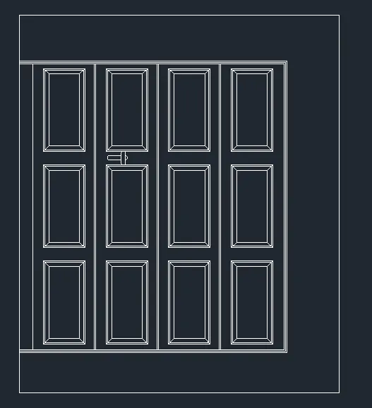
- DImensions and text layer is created and set as current from Layer properties manager.
- The first door is then dimesioned using DIMLINEAR command.
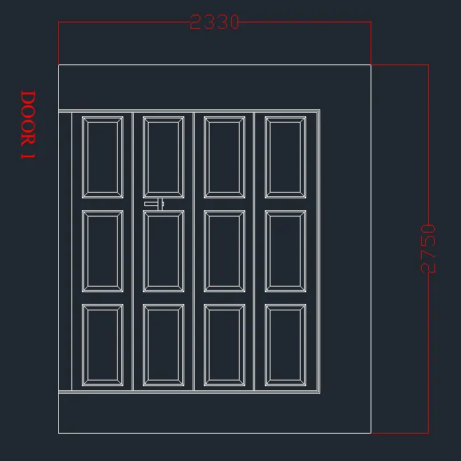
- The second door is created by copying and pasting the first door directly below it using ORTHO button and COPY commands.
- The array of rectangles is then erased using ERASE command.
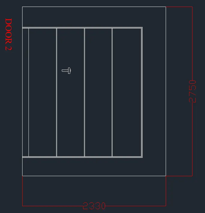
- Both the doors are then saved as blocks using BLOCK command.
RESULT:
The door types for warehouse as shown in the Figure are created and converted to blocks.
3)
AIM:
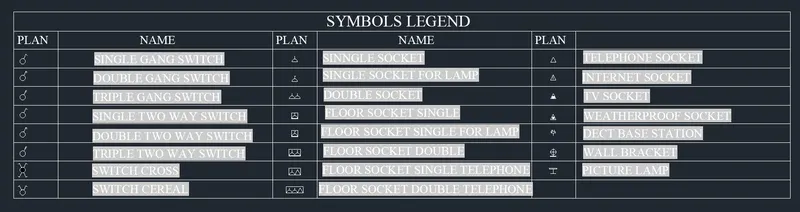
- To create each symbol as a block with the name given in the legend.
- After creating the blocks arrange them in the legend as shown in the Figure.
PROCEDURE:
- The first set of symbols are created using CIRCLE, LINE and COPY commands.
- Solid Hatches are used by giving HATCH command to get the black solid fill.
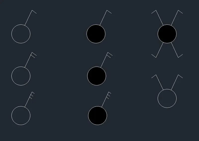
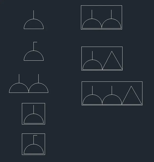
- The second set of symbols are created using CIRCLE, TRIM, RECTANGULAR and LINE commands.
- COPY command is used to copy repeated symbols.
- The third of symbols are created using LINE, DTEXT and CIRCLE commands.
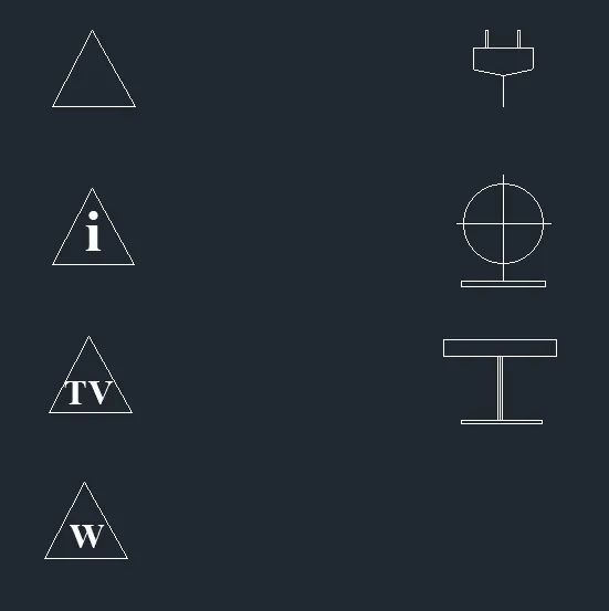
- All the symbols are then converted to blocks and named as per the drawing using BLOCK command.
- Using LINE command and TRIM command the Table is drawn.
- Using INSERT command the blocks are inserted.
- The headings are given using DTEXT.
- Once the blocks are inserted the Field option in the Insert panel is used to get the name of the blocks.
- They are then pasted in the name column.
FINAL RESULT:
The symbols are created and arranged in the legend as shown in the figure.
4) AIM:
- To create the door type for residential building as a block and save as type using given dimensions or assuming dimensions as per industry standards.
PROCEDURE:
- New drawing is opened with Imperial default setting and Enginnering units is selected.
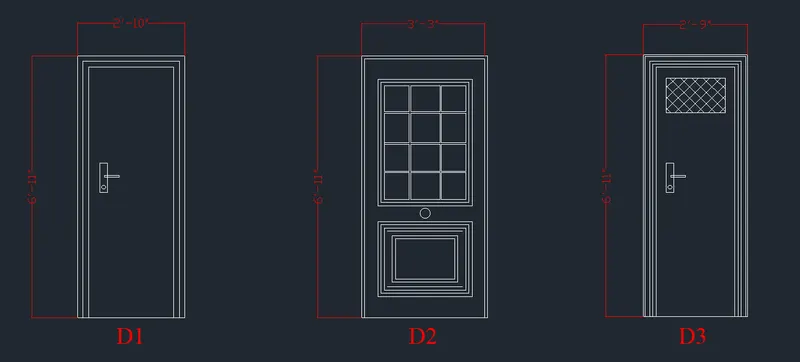
- The doors are created as per dimensions using the RECTANGULAR, PLINE, ARC, OFFSET and TRIM commands.
- Dimensions layer is created from the Layer properties manager and dimensions are given wherever required using DIMLINEAR command.
- The doors are then converted into blocks using BLOCK command.
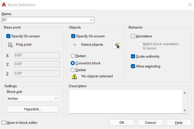
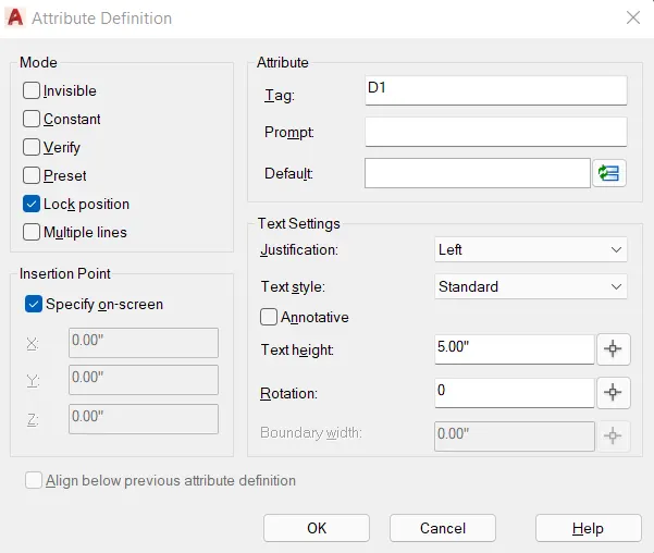
- The ATT command is used to provide the attributes to each block.
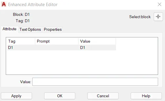
- The EATTEDIT command is used to assign value to the tag.
- The same procedure is repeated for all the created doors.
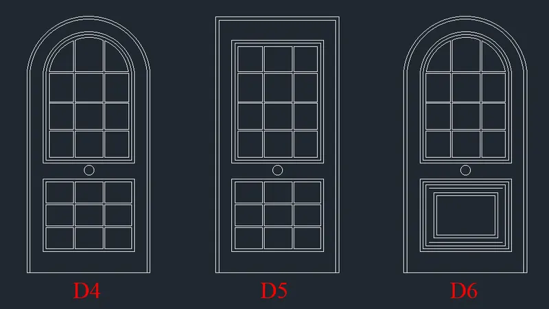
FINAL RESULT:
The door type for residential building is created as a block and saved as type using given dimensions or assuming dimensions as per industry standards.
5)
AIM:
- To create each shape as a block as shown in the Figure.
- Save the block and insert them on the table as shown in the Figure.
PROCEDURE:
- UNITS command is given and units are set to mm.
- The shapes are created and using LINE, PLINE and TRIM commands.
- They are dimensioned using DIMLINEAR command.
- They are then converted to blocks using BLOCK command.
- The table is then drawn using LINE and OFFSET commands.
- The blocks are inserted using INSERT command.
- DTEXT command is given and is copied and placed wherever text is necessary.
- The text is then editted by double clicking it or from properties.
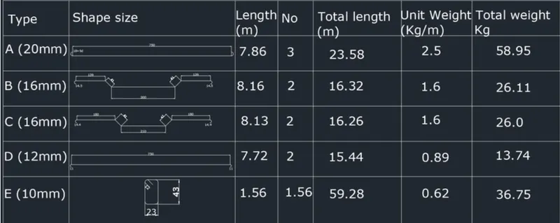
FINAL RESULT:
The shapes are created as blocks and inserted in the table as shown in the figure.