Analysis & Design of RCC shear walls in the model using ETABS
AIM:
- In the etabs file for a G+6 building that is provided. Run the analysis and design the RCC shear wall of size 300x1500 at grid A-11 in the structural model.
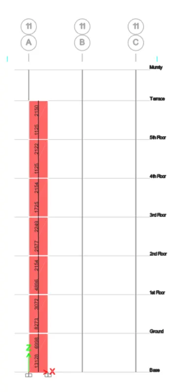
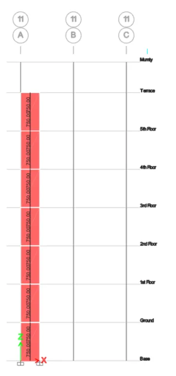
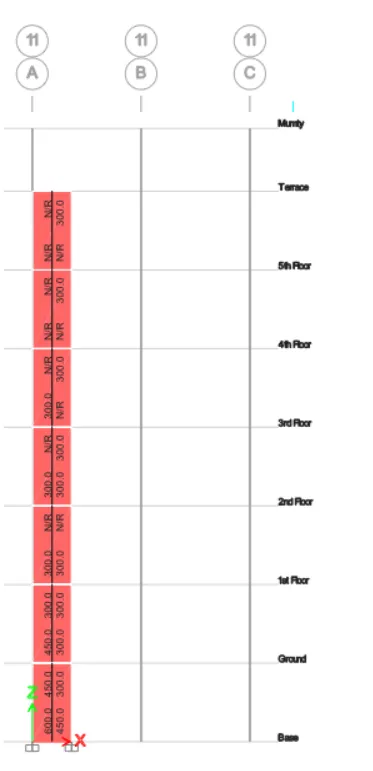
- Extract values of longitudinal steel ratio, boundary element length and shear reinforcing ratio from the design results.
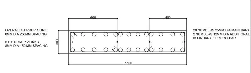
- Provide cross sectional steel arrangement of the shear wall from its base up to terrace, in compliance with provisions of IS 13920 – 2016. AutoCAD application can be used for this exercise. Alternatively, it can be drawn by hand as well.
- Provide elevation drawings of the reinforcement details of the shear wall from base up to terrace.
PROCEDURE:
STEP 1:
- Open the provided ETabs file.
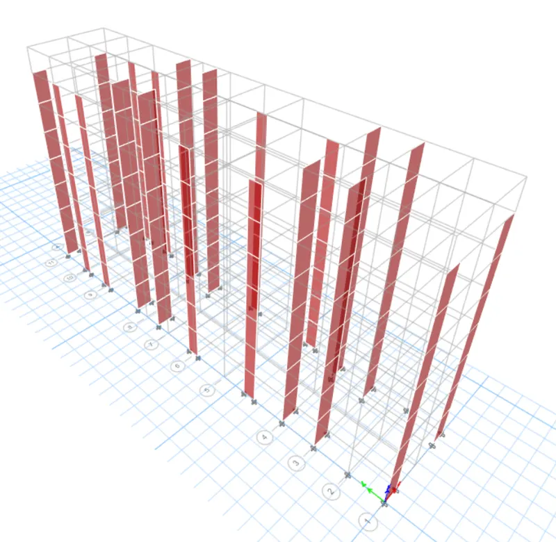
- Open the Plan view and locate the required shear wall.
- Select All stories option and then select the shear wall.
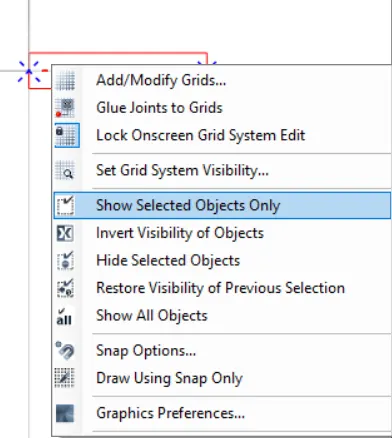
- Right click the shear wall-> Show selected objects only.
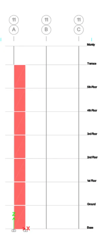
- Select Elevation view and set the view along Grid-11.
STEP 2:
- Run analysis.
- Click on the shear wall design icon.
- Once the analysis is complete toggle through the required Design details by clicking on Shear wall design Dropdown-> Display Design info.
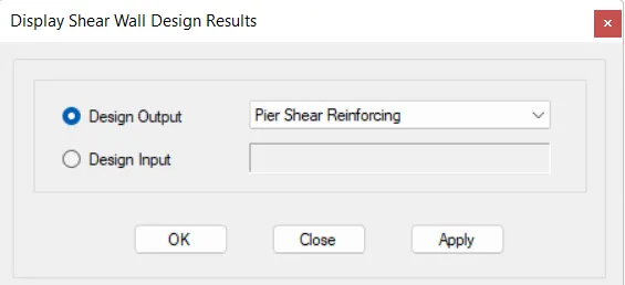
- Change the Design output to display the required output.
PIER LONGITUDINAL REINFORCING:
PIER SHEAR REINFORCING:
PIER BOUNDARY ZONE WIDTH:
Detailing Guidelines for shear wall:
- Classification of Shear wall as per IS-13920-2016 clause 10.1.4: hw/lw = 21000/1500= 14>2 -
Slender wall
Minimum net Vertical reinforcement as per IS 13920:2016 Clause 26.5.1.6 Table-1 -
2363 mm^2.
- Minimum vertical reinforcement within boundary element Table-1 (iii) -
1440 mm^2 on left(600mm width boundary element)
1080 mm^2 on right(450mm width boundary element)
- Minimum horizontal reinforcement in shear wall as per IS-13920-2016 Table-1 (iii)-
ph(min)= 750 mm^2/m
- Maximum diameter of rebar for shear wall as per IS-13920-2016 clause 10.1.8- 1/10th of wall thickness =
30mm, 25mm rebar is adopted
- Confining reinforcement spacing for boundary element as per IS-13920-2016 clause 10.4.4 -
Maximum spacing of confining reinforcement in boundary element 150mm.
- Confining reinforcement spacing within boundary element as per IS-13920-2016 clause 10.4.4 -
Ash= 452mm^2
Cross sectional steel arrangement of the shear wall :