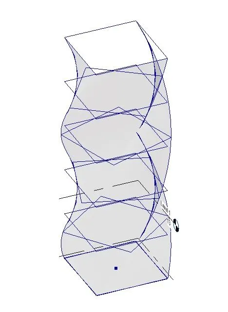
Creating Conceptual mass in REVIT and Creation of Sinusoidal curve and a Parametric stadium using Dynamo
1)
AIM:
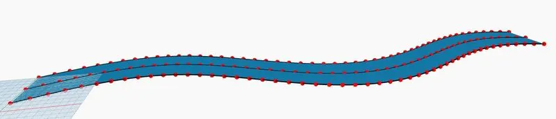
- To create a set of sinusoidal points and create a curve and create a surface out of the curve using Dynamo.
PROCEDURE:
STEP 1:
- Open Revit-> Manage tab-> Dynamo.
- Open a New file in Dynamo.
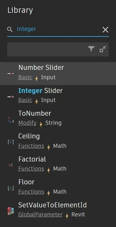
- In the search library search and add Integer sliders.
STEP 2:
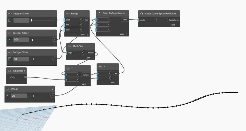
- Set the value for Start point, Step and End point using different sliders.
- Search and add Range from library and connect the nodes of the start, step and end points to the range respectively.
- Search and add Math.sin and connect to Range node.
- Search and add a Code block and rename it to Amplifier and set required value.
- Search and add Product node and connect Math.sin and Amplifier nodes to it.
- Search and add a Integer slider, rename it to Phase.
- Search and add a Add node and connect the Phase and product nodes to it.
- Search and add Point.Bycoordinates and connect x to Range node, connect y to Add node.
- Search and add NurbsCurve.ByControlPoints and connect it to Point.ByCoordinates node.
- A sinusoidal curve is created.
STEP 3:
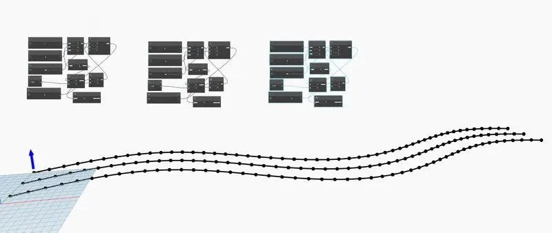
- Select and Copy all the nodes, Paste it twice to form two more curves.
- Edit the value of Phase slider to move the curves.
STEP 4:
- Search and add List Create, add two more items and connect all the three Nurbscurve nodes to each item.
- Search and add Surface.Byloft and connect it with List node.
- The required surface is formed from the sinusoidal curves.

FINAL RESULT:
A surface was created out of the created sinusoidal curves succesfully.
2)
AIM:
- To create a conceptual layout of floor plan in dynamo .
- To use the tools available in dynamo and link the lines to appropriate model elements in Revit by choosing the wall types and wall parameters.
- To make use of the sliders to slide through the height of the wall and length of the wall.
PROCEDURE:
STEP 1:
- Open Revit-> Manage tab-> Dynamo.
- Open a New file in Dynamo.
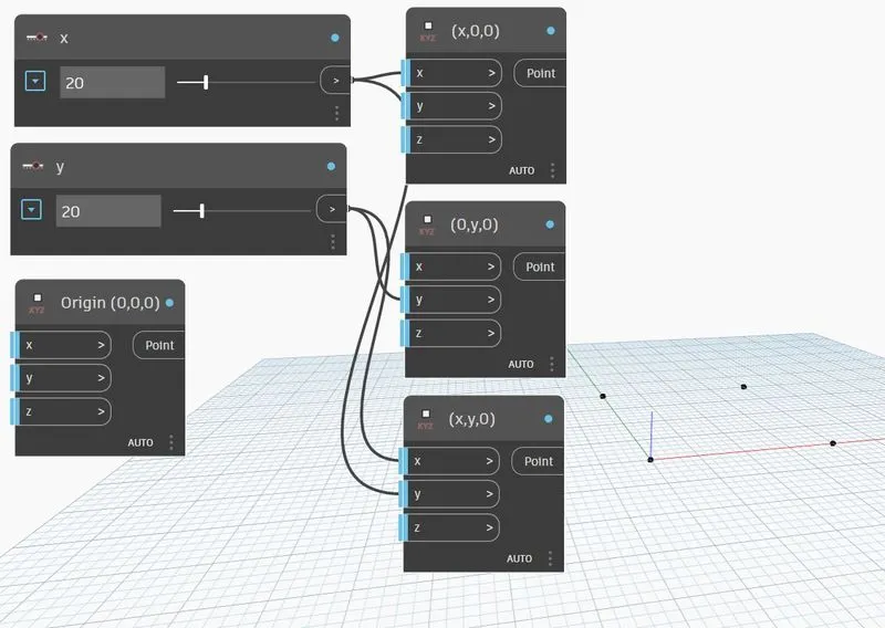
- In the search library search and add two Integer sliders, rename them as x and y.
- Search and add four Point.Bycoordinates and rename them as required.
- Connect the x,y integer sliders to the coordinate point nodes as follows to get the points in the required outline.
STEP 2:
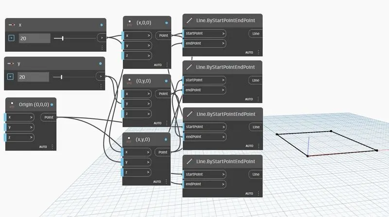
- Search and add Line.ByStartPointEndPoint four times.
- Connect them with the points to create lines and complete the outline.
STEP 3:
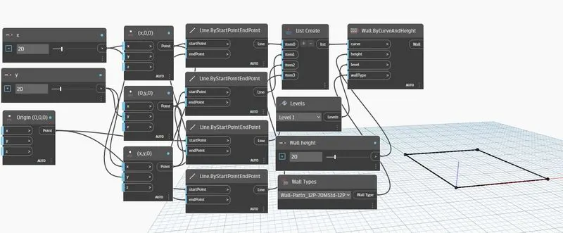
- Once the outline is created search and add List Create and add 3 more items.
- Connect the line nodes to the items in the List.
- Search and add Wall ByCurveand Height.
- Search and add levels.
- Search and add an Integer Slider and rename it as Wall height and provide appropriate wall height.
- Search and add Wall types and select required wall type.
- Connect the levels, Wall height and Wall types nodes to the Wall ByCurveand Height nodes respectively.
- Walls are now created.
STEP 4:
- Search and add Floor.ByOutlineTypeandLevel.
- Search and add Floor types and select required floor type.
- Connect outline node to list node.
- Floor type node and level nodes are also connected.
- The required floor is created.
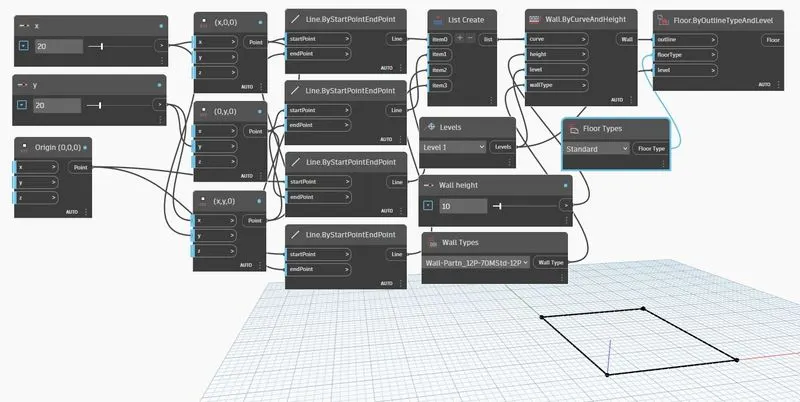
FINAL RESULT:
A conceptual layout has been created with wall parameters, wall types, floor types etc succesfully. The parameters of the walls can be editted using sliders.
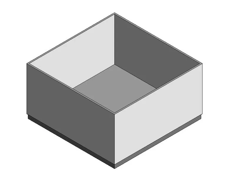
3)
AIM:
- To create an array of model elements in Revit and use dynamo to vary the properties of model elements by using the slider or code block.
PROCEDURE:
STEP 1:
- Open a new Architectural template in Revit.
- Go to Architecture tab-> Columns-> Column: Archituctural.
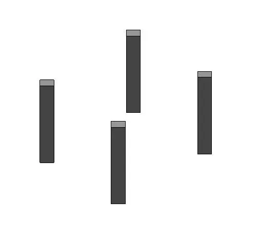
- Place four columns in the workspace.
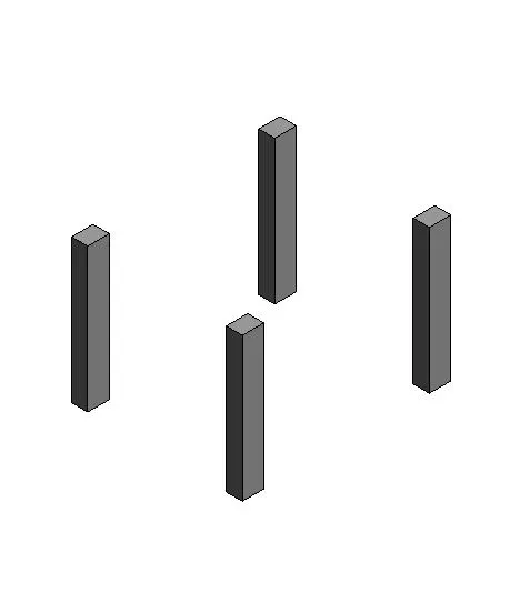
STEP 2:
- Go to Manage tab-> Dynamo.
- Open a New file in Dynamo.
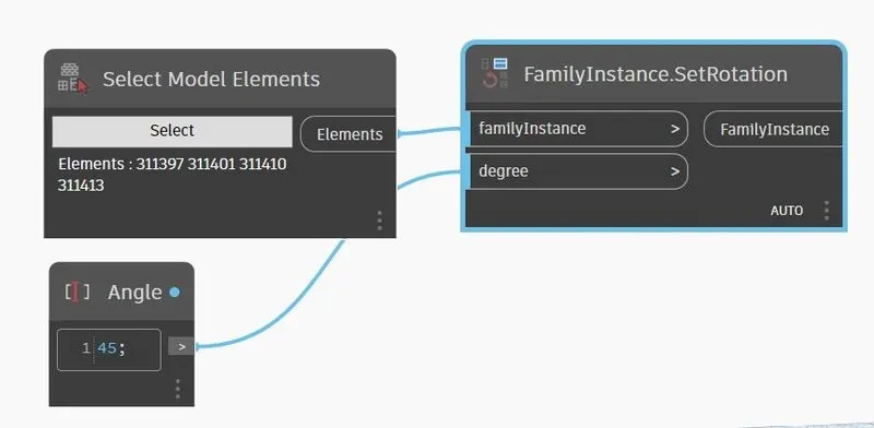
- In the Search library search and add Select model elements.
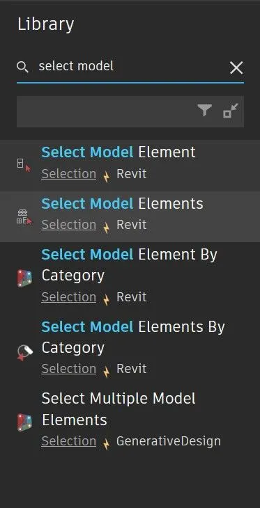
STEP 3:
- Click on Select in Search Model Elements, go to Revit screen and select the created columns.
- Search and add Code block, rename it as angle and provide a value.
- Search and add FamilyInstance.SetRotation, connect the Angle node to degree and Element node to Familyinstance.
- The selected columns are rotated about their individual axis to the provided angle.
FINAL RESULT:
Properties of model elements have been varied using Code block in Dynamo succesfully.
4)
AIM:
- To create a conceptual mass in Revit and develop a parametric column by dividing the surfaces.
- To use triangular bent or square shaped panels to add finish to the parametric column.
PROCEDURE:
STEP 1:
- Open new conceptual mass template from Revit-> Families-> New.
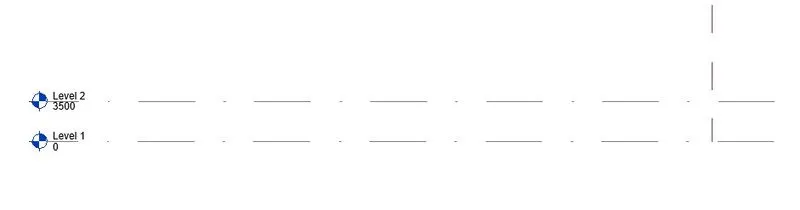
- Open an Elevation view from Project Browser.
- Go to Datum tab-> levels and add another level at required height.
STEP 2:
- Open Floor plan view from Project browser.
- Go to Create-> Model-> Spline and draw a curved line using control points.
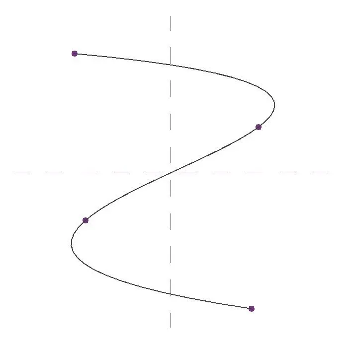
- Open 3D view, select the control points and set them as work planes one by one from Work plane panel-> Set-> Set Work plane.
- Then select Show work plane.
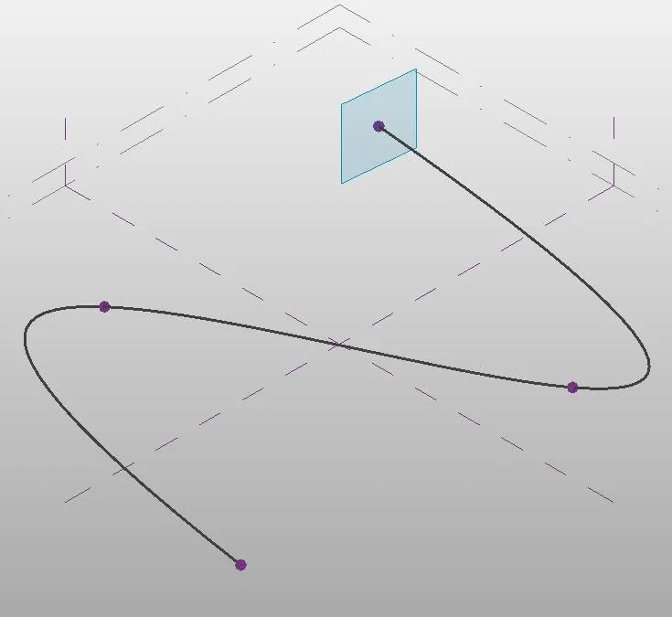
STEP 3:
- Select Circumscibed polygon tool from Draw panel.
- Draw a polygon on all the work plane.
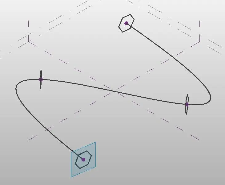
STEP 4:
- Select all the polygons and spline-> Create form-> Solid Form.
- A solid form is created along the spline.
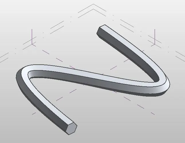
STEP 5:
- Select the solid form.
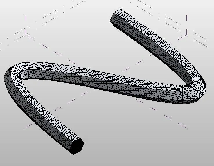
- CLick on Divide surface in the ribbon.
- Select the solid form again, in Property browser-> Pattern select Triangle (bent) pattern.
- Adjust U and V grids from Property browser.
- The required conceptual mass is formed.
FINAL RESULT:
A conceptual has been created with Divided surface and triangular (bent) panels have been added succesfully.
5)
AIM:
- To work on developing a Parametric High rise tower using Dynamo.
PROCEDURE:
STEP 1:
- Open Revit-> Manage tab-> Dynamo.
- Open a New file in Dynamo.
- In the search library search and add four Integer sliders, rename them as follows;
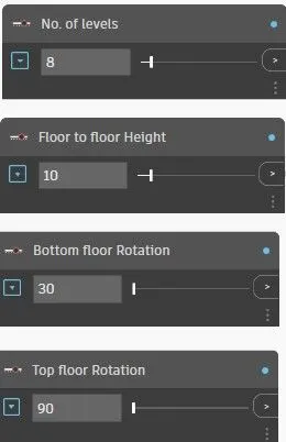
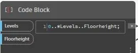
- Create a Code block with the following code.
- Connect the No.of levels and Floor height nodes to the code block respectively.
STEP 2:
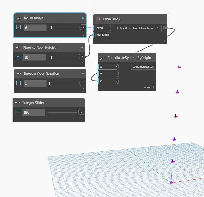
- Search and add CoordinateSystem.ByOrigin.
- Connect the Code block node to Z axis.
- Levels have been created with required height.
STEP 3:
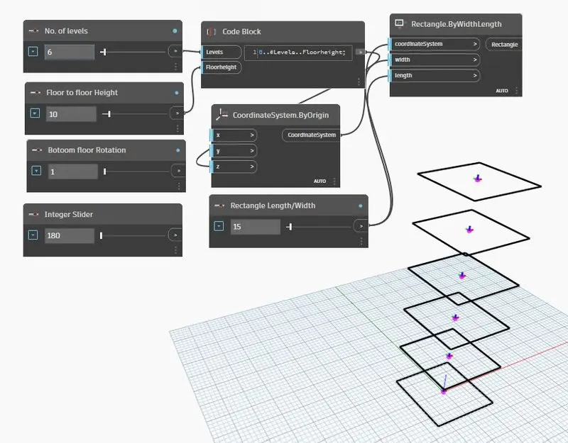
- Search and add Rectangle.BywidthLength.
- Search and add Integer slider, rename it as Rectangle width/Length and connect the node to width and length nodes.
- Connect the coordinate system node to coordinate system.
- Rectangles have been formed in each level.
STEP 4:
- Search and add Point.Origin, Vector.Zaxis
- Search and add Code block and code it as Bottom, Top and levels
- Search and add Geometry rotate and connect the geometry, origin, axis and degrees nodes appropriately.
- Search and add Polysurface.Byloft and connect Geometry node to cross section.
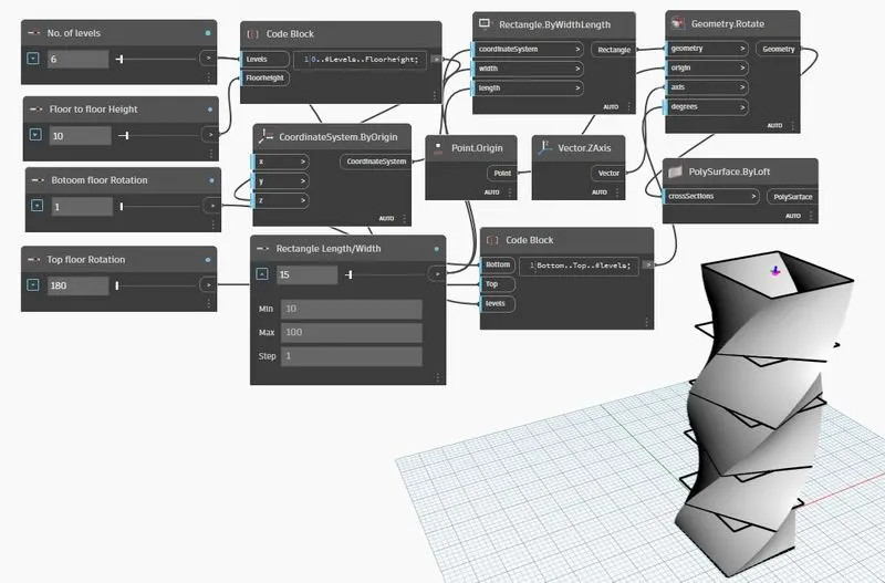
FINAL RESULT:
The require parametric high rise building has been created suing Dynamo succesfully.