Creating a Wardrobe detailed drawing, Floor Plan, Kitchen Layout and Column Detail using AutoCad
1) Aim:
To draw the elevation and details of a wardrobe as shown in the figure and provide dimensions and text with use of layers, proper text styles and dimension methods.
Procedure:
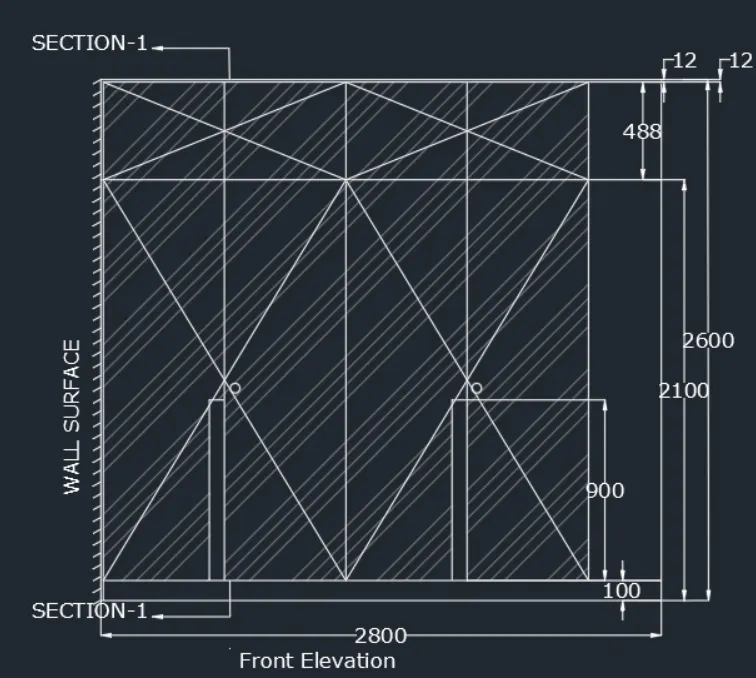
Front elevation:
- Units are set to mm.
- Limits and Lim max are also set using
- The outlines of the drawings are drawn using RECTANGULAR command and lines using LINE command wherever necessary.
- OFFSET command is also used.
- Then HATCH command and Internal point method is used to provide the hatch inside the outline.
- Using QLEADER command provide the leaders.
- Dimensions are provided using the Dimension dropdowns in the Annotate panel.
- The Wall surfaces are provided by creating an outile with PLINE command and inserting Hatch using HATCH command and deleting the lines later.
Plan:
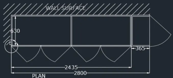
- The same procedure as the front elevation is followed for creating the outline and hatches.
- For the Doors in the plan CIRCLE radius command is used to create the arc and the LINE command is used to complete the door. The rest of the circles are trimmed off using TRIM command.
- Dimensions are then provided using DIMLINEAR command.
Carcase elevation:
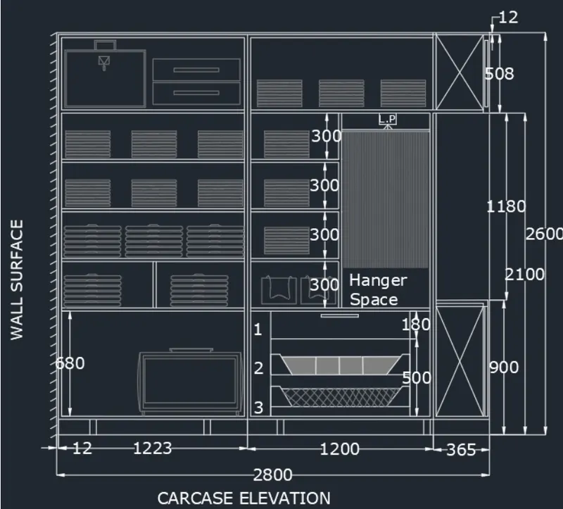
- The same procedure as the front elevation is followed for creating the outline and hatches.
- All the contents of the Cabinet are drawn using various commands like RECTANGULAR, LINE, PLINE etc.
- The drawing is then dimensioned using the Dimension dropdowns in the Annotate panel.
Side elevation:
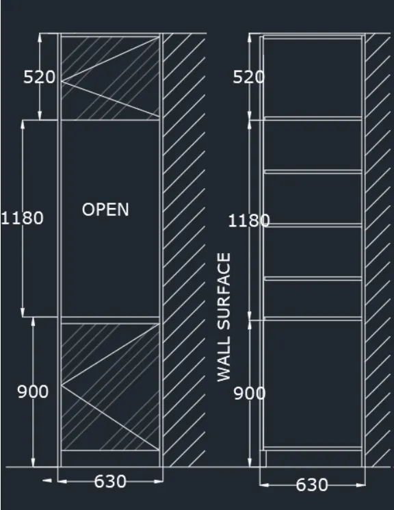
- The same procedure as the front elevation is followed for creating the outline and hatches.
- The drawing is then Dimensioned using the Dimension dropdowns in the Annotate panel.
Layers:
- The components of the drawing are then placed in their appropriate layers using Layer properties manager.
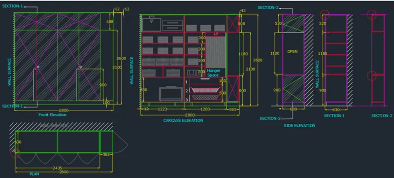
Result:
- The elevation and details of a wardrobe as shown in the figure is drawn. Dimensions and text with use of layers, proper text styles and dimension methods are provided.
2) Aim:
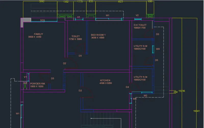
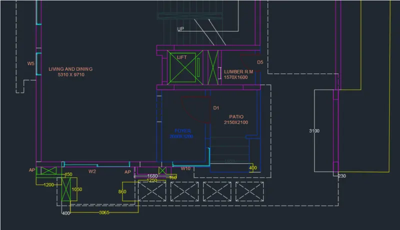
- To draw the given floor plan and provide dimensions and text as per proper techniques.
Procedure:
- Units are set to mm.
- Limits and Limmax are also set.
- Using XLINE command the infinite lines are drawn.
- The internal and external walls are drawn using OFFSET tool as per dimensions.
- The rest of the lines are trimmed off using TRIM.
- The canopy is created using CIRCLE, ARC, BLEND, PLINE commands.
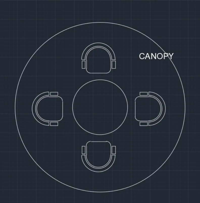
- The dimensions and of the drawing are provided using the Dimension dropdowns in the Annotate panel.
- The text is provided using MTEXT command.
- The dotted lines are created by changing the linetype to dotted lines in the Linetype manager dialogue box using LINETYPE command.
- The stairs, doors, windows and ventilators are created using various commands like OFFSET, LINE, PLINE, ARC etc wherever necessary as per dimensions.
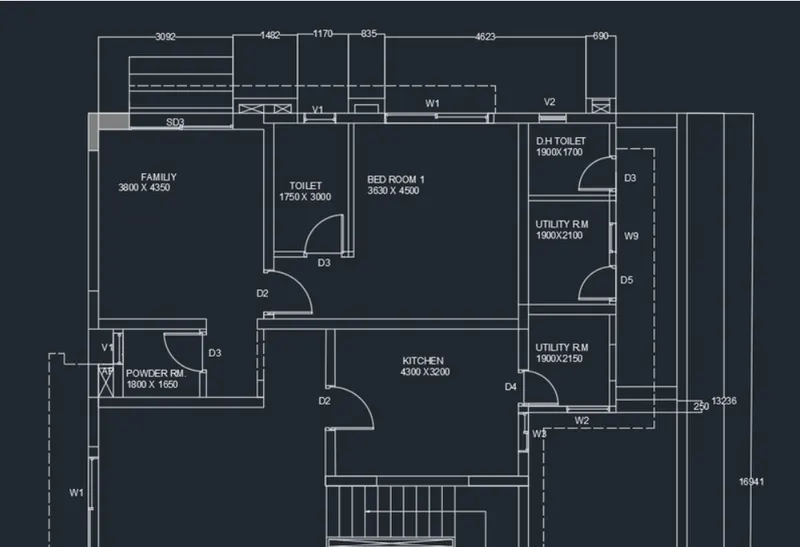
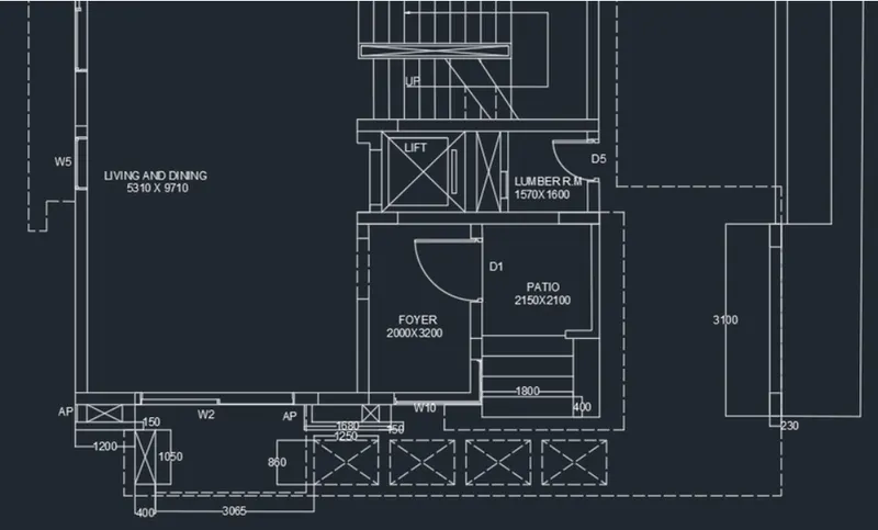
- The components of the drawing are then placed in their appropriate layers using Layer properties manager.
Result:
The given floor plan is drawn. Dimensions and text are provided as per proper techniques.
3)
Aim:
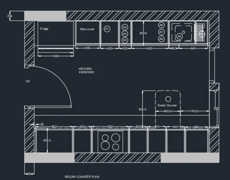
- To create a kitchen layout and give proper dimensions and text.
Procedure:
- Units are set to mm.
- Limits and Lim max are also set using
- The outlines of the drawings are drawn using RECTANGULAR command and lines using LINE command wherever necessary.
- OFFSET command is also used.
- The dotted lines are created by changing the linetype to dotted lines in the Linetype manager dialogue box using LINETYPE command.
- Then HATCH command and Internal point method is used to provide the hatches inside the outline.
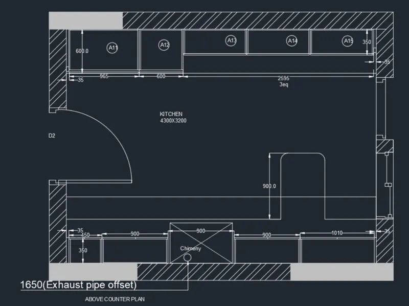
- Using the COPY command another copy is created for the above counter plan.
- The various commponents of the kitchen like slabs, fridge, microwave ovens are created using OFFSET, FILLET and LINE tools, CIRCLE command is also used wherever necessary.
- The dimensions and of the drawing are provided using the Dimension dropdowns in the Annotate panel.
- The above counter plan is created using COPY command once the outline was finished.
- The required changes are made using LINE, OFFSET, FILLEt and CIRCLE commands.
- The dimensions and of the drawing are provided using the Dimension dropdowns in the Annotate panel.
- Using LAYER command components of the drawing are then placed in their appropriate layers in the Layer properties manager.
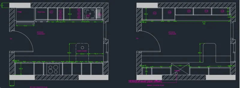
Result:
- The required kitchen layout is created and proper dimensions and text are given.
4)
Aim:
- To create a column detail as shown in the figure and insert texts and dimensions.
Procedure:
- Using RECTANGULAR command the tables are drawn.
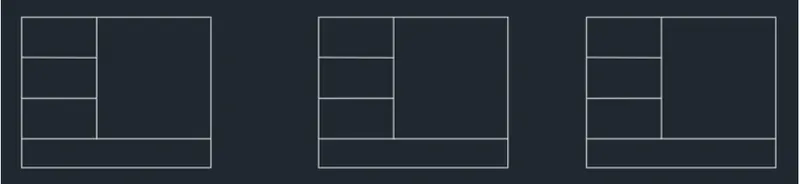
- The text is then inserted using DTEXT command.
- The text is justified accordingly using JUSTIFY option from properties.
- The column reinforcement is created using RECTANGULAR, OFFSET. LINE and CIRCLE commands.
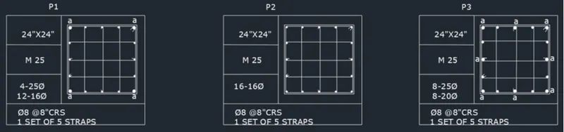
Result:
- The required column detail is created with texts and dimensions as shown in the figure.
5)
Aim:
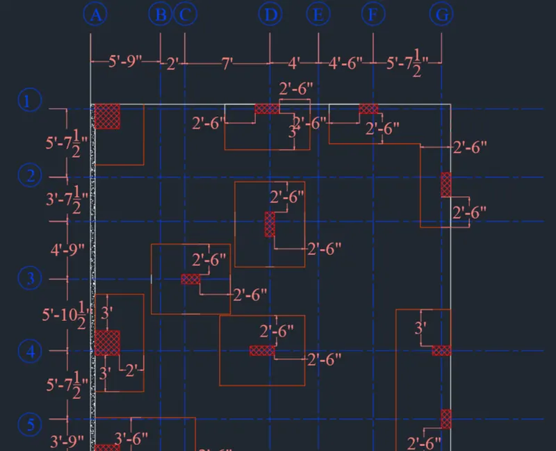
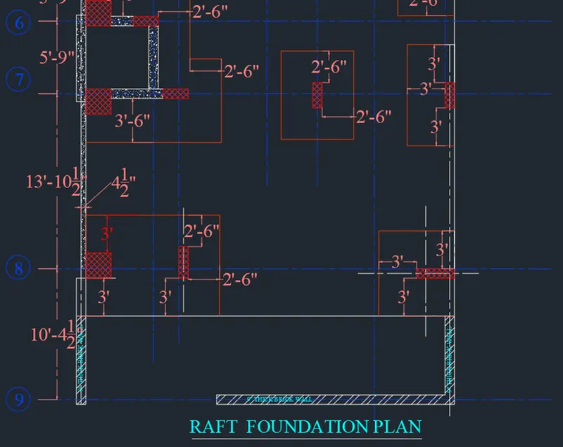
- To draw the raft layout as shown in the figure. The column sizes must be assumed.
Procedure:
- Using RECTANGULAR command and dimensions the rectagle is drawn.
- The dotted lines are created by changing the linetype to dotted lines in the Linetype manager dialogue box using LINETYPE command.
- The lines are then offseted using OFFSET command to create the outline.
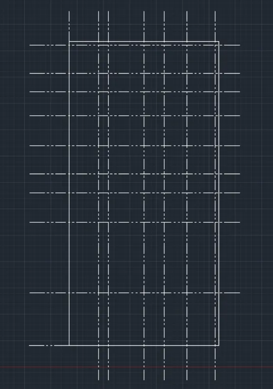
- The walls are created using OFFSET command.
- The columns are created using RECTANGULAR command.
- They are hatched using the appropriate hatch from HATCH pallette.
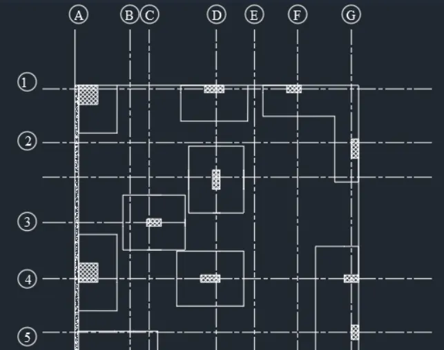
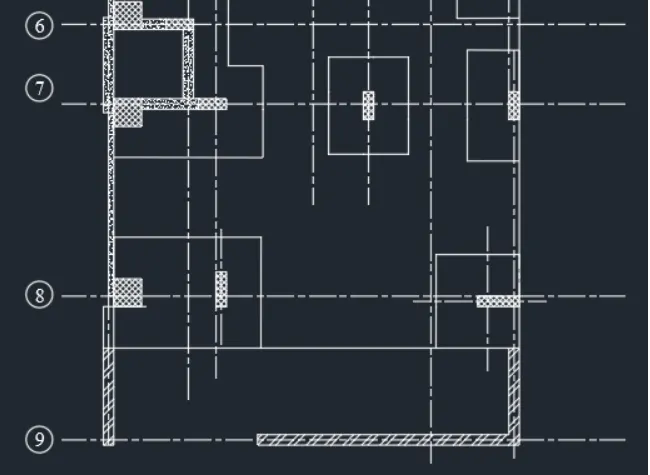
- The text and dimensions are given from Annotate pallette.
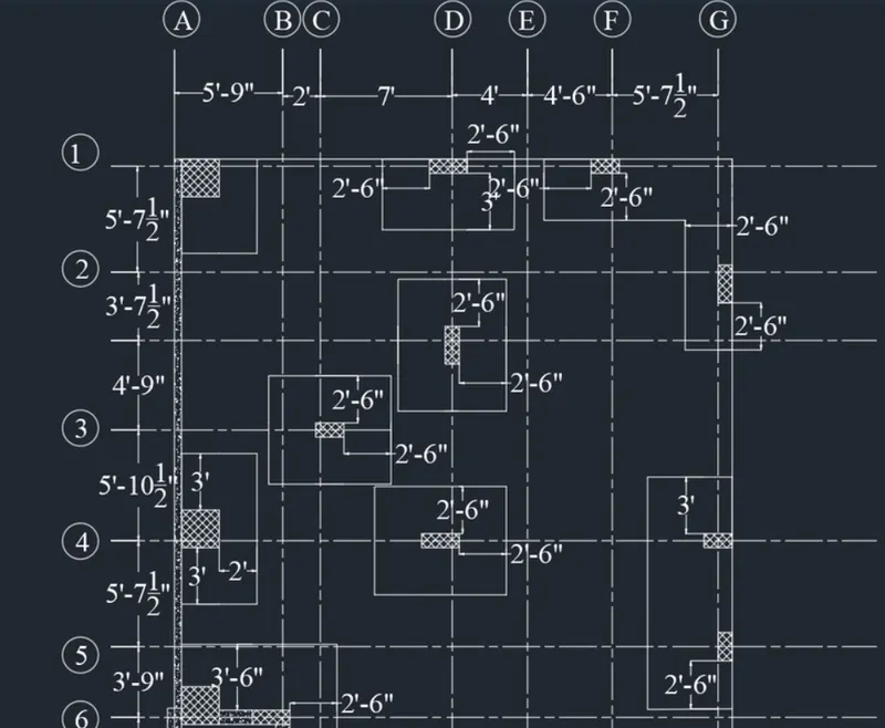
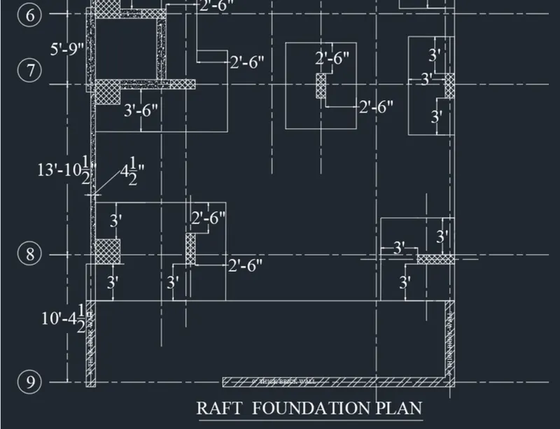
- Using LAYER command components of the drawing are then placed in their appropriate layers in the Layer properties manager.
Result:
- The raft layout as shown in the figure is drawn by assuming the column sizes.