Project 2_Creating a 3D rendered model for a Residential Building in AutoCad
1)
AIM:
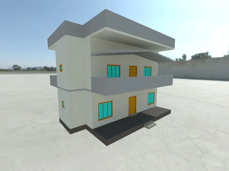
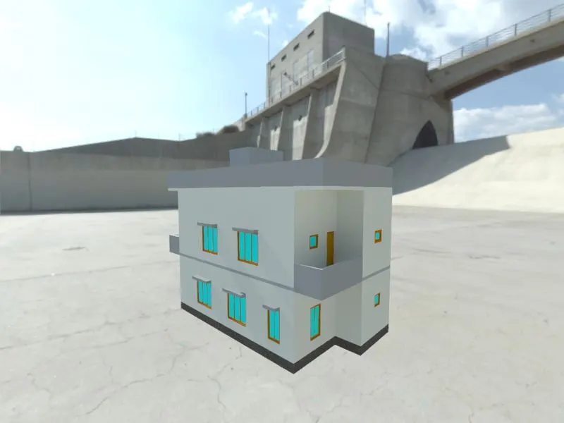
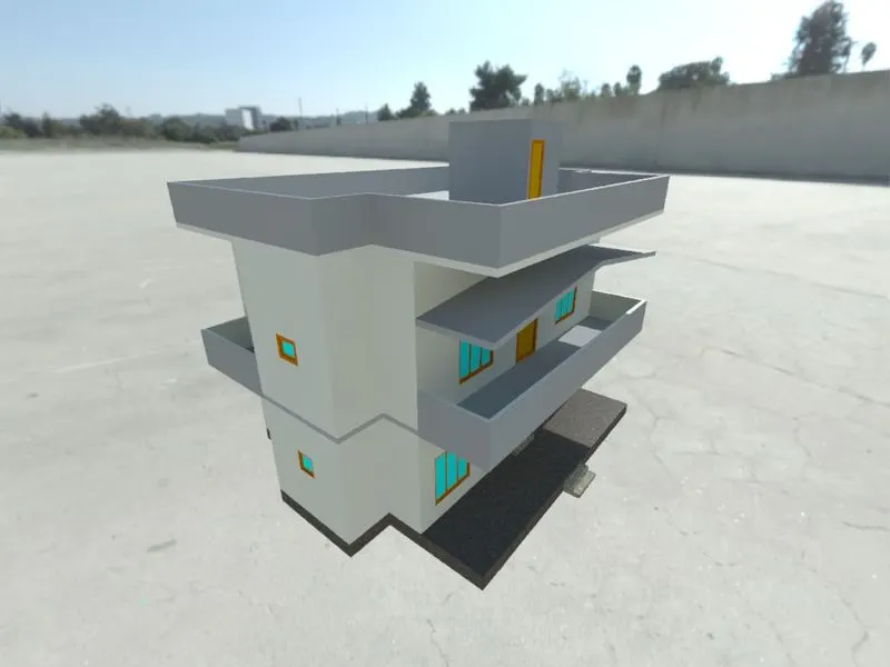
- To create a 3D model of a residential building with a rendered view.
INTRODUCTION:
The Architectural drawings of the required building are drawn in 2D. Using the drawings as reference the 3D model is then developed using the 3D modelling workspace in AutoCAD. It is then rendered as required.
PROCEDURE:
STEP 1:
- AutoCAD is started with Metric as default setting.
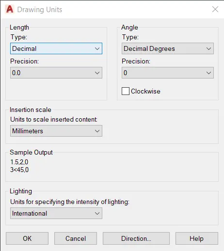
- The Type is set to 'Decimal' and Precision is set to '0.0' using UNITS command.
- Workspace is set to 3D Modelling.
STEP 2:
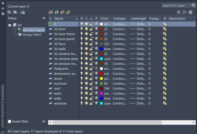
- Using Layer Properties Manager is the ribbon all the required layers are created.
STEP 3:
- Top view is selected in the View cube.
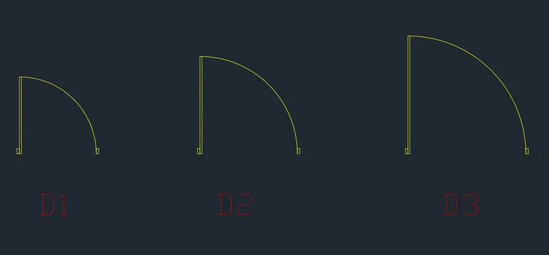
- Doors is set as the current Layer.
- RECTANGULAR command is used to create the hinge.
- LINE and OFFSET commands are used to create the door frame.
- The swing is created using CIRCLE command and the rest of the circle is trimmed off using TRIM.
- Using the same procedure three doors of required sizes are created.
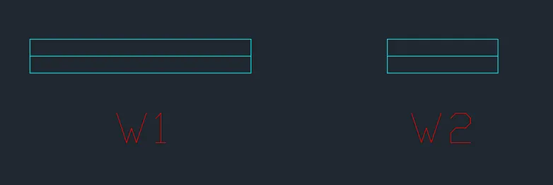
- Windows is set as the current Layer.
- RECTANGULAR and LINE commands are used to create the windows.
- Two windows of two different sizes and a ventilator are created.
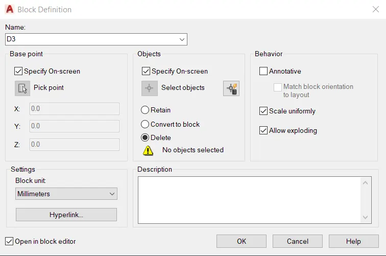
- The created doors and windows are then converted into blocks using BLOCK command.
- The doors are named D1,D2, D3.
- The windows are named W1 and W2.
- The ventilator is named V respectively.
- They are made into Dynamic blocks using BEDIT command.
STEP 4:
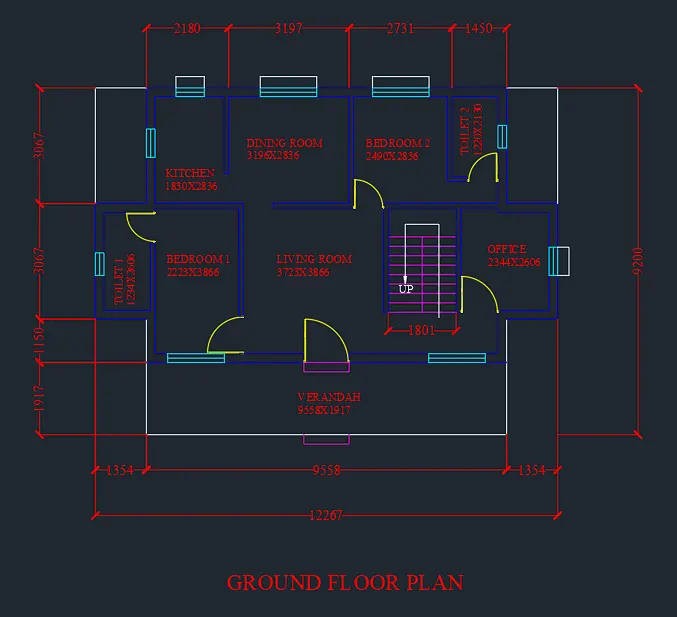
GROUND FLOOR PLAN:
- Current layer is set to Walls.
- The construction lines are drawn using XLINE command.
- The Walls are then drawn using OFFSET and TRIM commands.
- The outer walls are of 230 mm thickness and inner walls are 120mm thickness.
- The Layer is set to Doors and the INSERT command is given to insert the doors wherever necessary.
- The Layer is set to Windows and INSERT command is given to insert the windows and ventilators wherever necessary.
- The Layer is set to Stairs and the stairs are drawn using LINE and OFFSET commands.
- Dimensions layer is set as current.
- DIMSTYLE command is used to edit the Dimension Style.
- The drawing is then dimensioned using DIMLINEAR and DIMCONTINUE commands.
STEP 5:
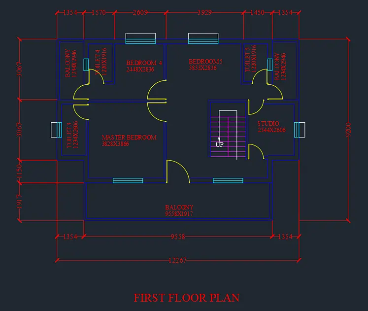
FIRST FLOOR PLAN:
- From the layer properties manager all layers except walls and stairs are frozen.
- The drawing is then copied and pasted using COPY command.
- The inner walls are erased using ERASE command and the walls are drawn wherever required using LINE and OFFSET command.
- The Layer is set to Doors and the INSERT command is given to insert the doors wherever necessary.
- The Layer is set to Windows and INSERT command is given to insert the windows and ventilators wherever necessary.
- The Layer is set to Stairs and the stairs are drawn using LINE and OFFSET commands.
- Dimensions layer is set as current.
- The drawing is then dimensioned using DIMLINEAR and DIMCONTINUE commands.
STEP 6:
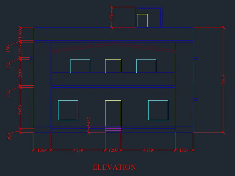
ELEVATION:
- The Plan is copied using COPY command and placed elsewhere.
- Construction lines are drawn as projections for the elevation using XLINE command.
- The Plinth, sill and lintel levels are drawn using OFFSET command.
- The unnecessary lines are trimmed using TRIM command.
- The components are then placed in the appropriate layers from Layer properties manager.
- Dimensions layer is set as current.
- The drawing is then dimensioned using DIMLINEAR and DIMCONTINUE commands.
STEP 7:
- The home icon is selected in the View cube.
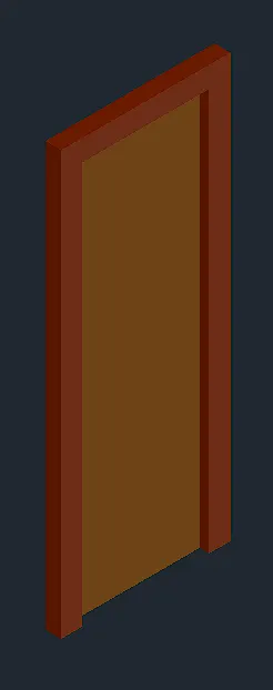
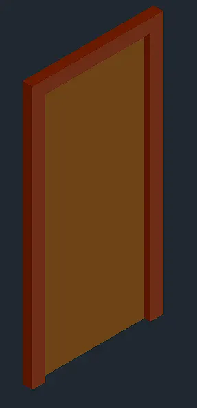
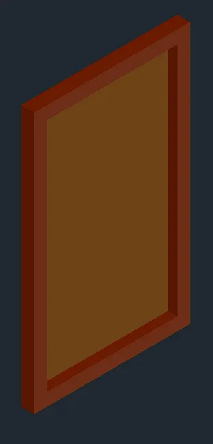
- Doors are created using RECTANGULAR and OFFSET commands.
- The frame and panel are created using EXTRUDE and SUBTRACT commands and placed in appropriate layers.
- All three sizes of doors are created with the same procedure.
- They are then rotated as per required using ROTATE3D command before use.
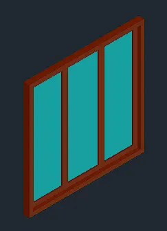
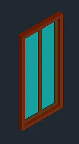
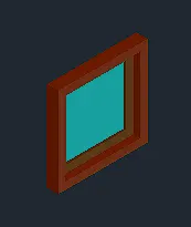
- RECTANGULAR and OFFSET commands are given to create the window frame, mullions and glass.
- They are then created in 3D using EXTRUDE and SUBTRACT commands.
- Both the sizes and the ventilator are created using the same procedure.
STEP 8:
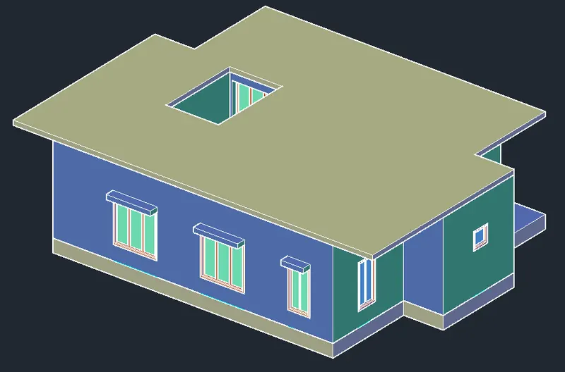
GROUND FLOOR 3D:
- The ground floor plan is copied and pasted in another location using COPY.
- The 3D walls layer is set to current.
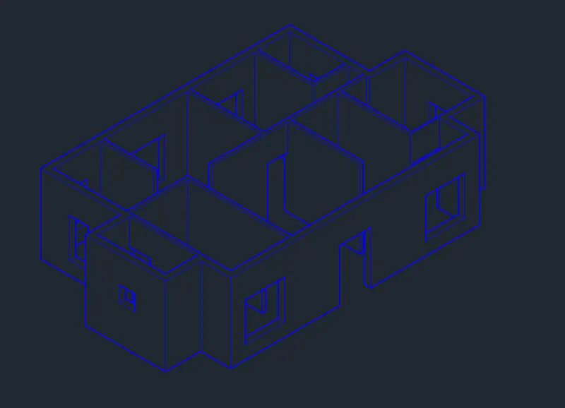
- The walls are created into regions using BOUNDARY -> Region and selecting the walls.
- The walls are then extruded as per required height.
- RECTANGULAR command is used to draw a rectangle wherever doors and windows are required.
- The rectangles are then extruded as per required size for the doors, windows and vents.
- The doors, windows, and vents are then selected individually and moved in the z axis using MOVE -> Displacement.
- The solids are then subtracted from the Walls using SUBTRACT command.
- The gaps for the doors, windows and vents are now created.
- The walls are now joined using UNION command.
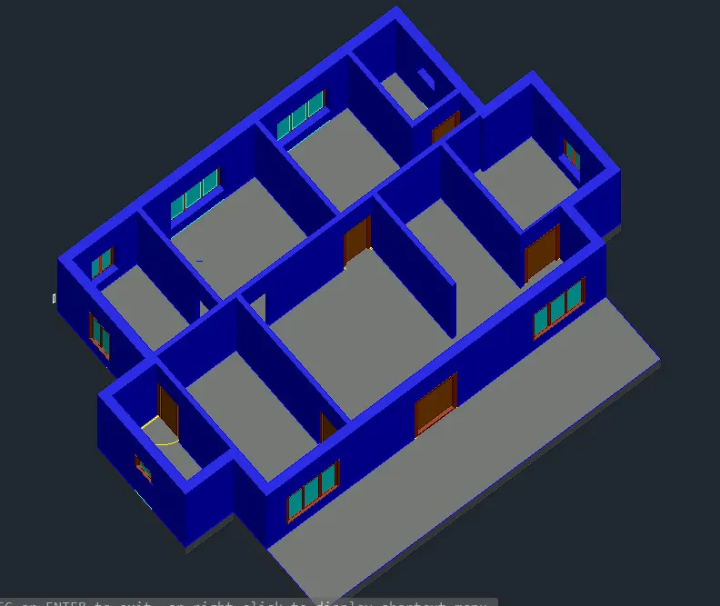
- The created doors, windows and vents are now copied and pasted in the gaps of the walls that were created using COPY command.
- They are rotated as required using ROTATE3D command before placing.
- 3D floors is set as current layer.
- The outline of the plan is drawn using PLINE command.
- It is converted into region using REGION command.
- The region is then extruded 450 mm in the negative z axis to create the floor till the ground level.
- The ceiling for the ground floor is also created with 3D floors layer.
- In the 2D wireframe view a rectangle of the size of the staircase is drawn and extruded using RECTANGLE and EXTRUDE.
- It is then subtracted from the Floor using SUBTRACT command creating gap for the staircase.
- The 3D stairs layer is set as current.
- A solid of the required size is created by extruding the staircase rectangle creating a stair.
- It is then copied and placed multiple times to create multiple stairs.
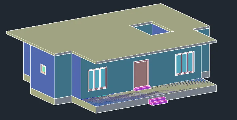
- The rectangles for the sunshade are moved in the z axis using MOVE -> Displacement.
- They are moved to 3D walls layer using MATCHPROP
- They are then extruded using EXTRUDE to create the sunshades.
STEP 9:
STAIRS:
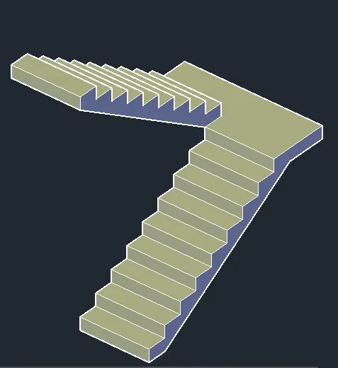
- The Top view is selected and one tread and riser is drawn using PLINE command.
- It is then copied and pasted as many times as required to create a flight of stairs.
- It is then closed and made into a regoin by BOUNDARY -> Region command.
- The home icon is given in the view cube the plan is selected and joined using JOIN.
- It is then rotated 90 degrees in the x Axis using ROTATE3d command
- Extrude it using EXTRUDE command to create a flight of stairs, this solid is then copied, rotated and pasted to create another flight of stairs using COPY, ROTATE3D commands.
- The landing is then created by creating a rectangle and extruding it.
- It is joined using UNION command to make one solid.
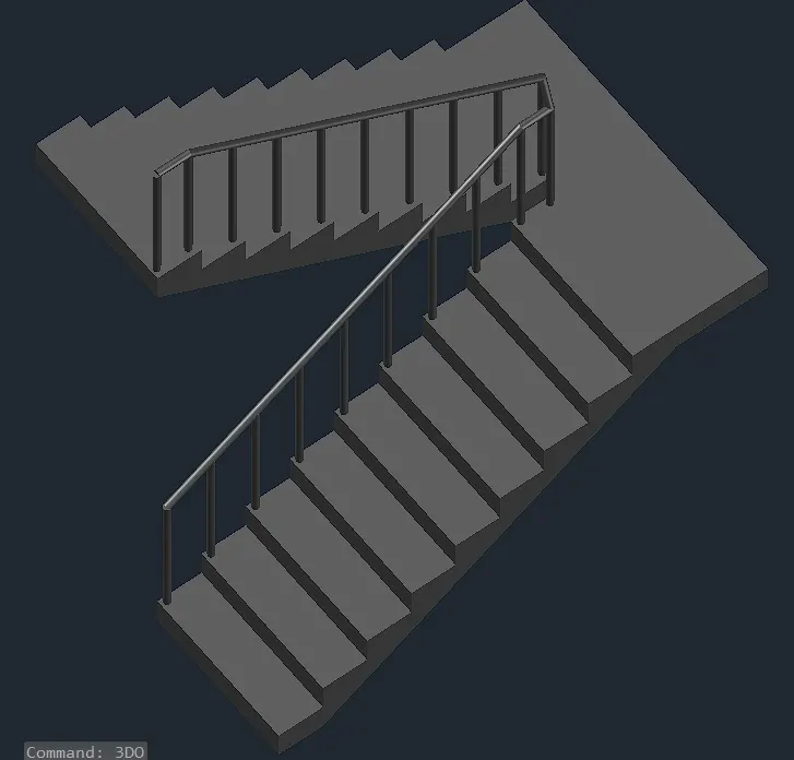
- UCS is placed on the tread and a circle is created using CIRCLE command.
- It is then extruded to create the balustrade.
- The solid is then copied using COPY command and pasted on every stair using the tread as endpoint.
- A polyline is created using 3P command joins all balustrades.
- A circle is then created using CIRCLE command and is extruded on the Polyline using EXTRUDE-> Path to get the railings.
- The Railings and balustrades are then joined with the stairs to make a single block using UNION command.
- It is then added to the 3D stairs layer.
- It can be copied and placed in the Ground and first floors.
STEP 10:
FIRST FLOOR 3D:
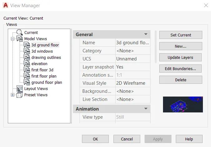
- For easier navigation Views of the architectural drawings and the 3d models are created using VIEW command.
- The first floor plan is copied and pasted on a copy of the groundfloor ceiling.
- The 3D model of the first floor along with balconies and parapet walls is created with the same procedure as the groundfloor.
- It is then placed on top of the ground floor ceiling.
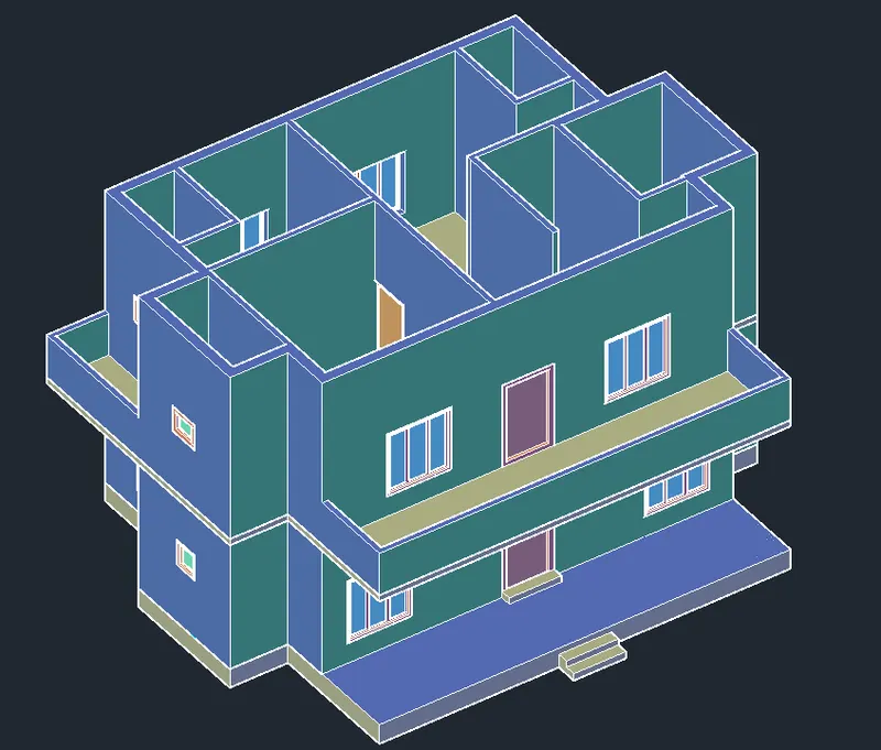
- The stairs are also placed on top of the previous flight of stairs.
STEP 11:
TERRACE:
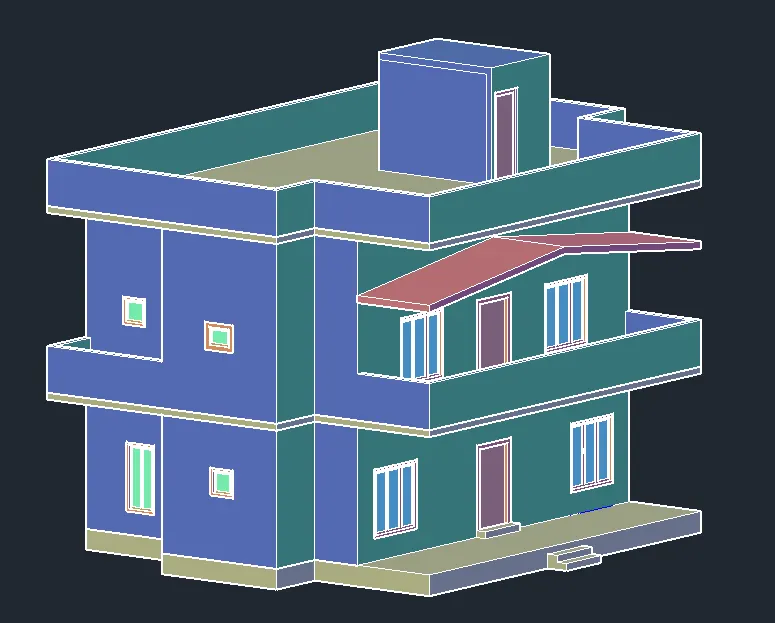
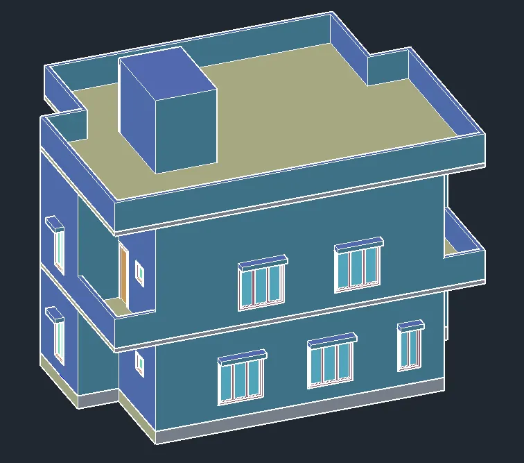
- The terrace is created with the copy of the ceiling of ground floor.
- The parapet walls are created using EXTRUDE command and is placed in the 3D walls layer.
- It is then copied and placed along with the ceiling above the first floor to create the terrace.
STEP 12:
RENDER:
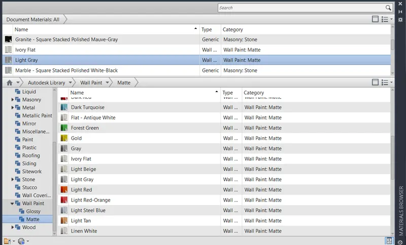
- MAT command is given to open the Material browser.
- In the material browser different types of paints, stones, floors etc are navigated and assigned to the required selections.
- Different camera views are created and saved to get different views of buildings using CAMERA command.
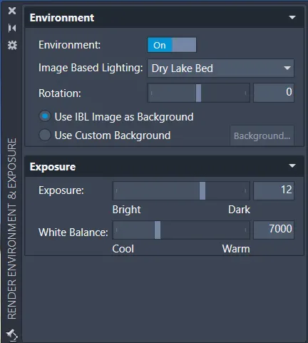
- Visualize tab is opened and Render dropdown Environment is chosen as per requirement.
- Appropriate exposure is chosen to get good view of the model.
- The camera views are then selected.
- Realistic visual style is selected.
- RR command is given to create the renders for the different views.
FINAL RESULT:
The 3D model has been created, materials have been assigned and the model is rendered using AutoCAD software.