Conceptual design of a building with columns and shear walls
1)
Restraints of floor shrinkage:
Observations:
Option a)
- Full restraints are present in all corners equally split in both X and Y directions.
Option b)
- Restraints are provided along the centre of edges in both directions and the corners are left free.
Option c)
- The restraints provided are non-uniform.
- In the Y direction there are two restraints on opposite edges.
- In the X direction there are two restraints joined together in one edge while the edge has no restraints.
Conclusion:
- With the observations made based on the criteria it is concluded that Option (a) has higher restraint to shrinkage, therefore leads to cracks in the floor.
- In option (b) restraint to shrinkage is comparatively lower, cracks in the floor will form but not as much as option (a).
- In option(c) the restraint to shrinkage is ineffective, this will lead to very less cracks in the floor.
Lateral stiffness:
Observations:
Option a)
- Comparatively lower lateral stiffness in both X and Y.
Option b)
- Restraints are provided along the centre of edges in both directions and the corners are left free.
Option c)
- Non-uniform lateral stiffness in both X and Y directions.
Conclusion:
- With the observations made based on the criteria of Lateral stiffness in all the three options it is concluded that option (b) will provide higher lateral stiffness for a pure seismic acceleration in both X and Y directions.
Torsion with respect to Vertical axis:
Observations:
Option a)
- Due to the presence of corner walls resistance to twist is high.
Option b)
- The walls in the edge also provide good resistance to twist but is comparatively lower to option (a)
Option c)
- Due to the irregular placement of the walls the resistance to twist is very low.
Conclusion:
- With the observations made based on the criteria it is concluded that option (a) provides the highest resistance to twist among the three options due to the presence of corner walls.
- Option (c) is the least resistant to twist.
Vertical reinforcement for similiar base capacity:
Observations:
Option a)
- Walls are subjected to nominal flexural moment and heavy twisting moment.
Option b)
- Walls are subjected to nominal flexural moment and regular twisting moment.
Option c)
- Walls are subjected to heavy flexural moment and heavy twisting moment.
Conclusion:
- With the observations made based on the criteria it is concluded that option (c) will require highest Vertical reinforcement.
- Option (b) will require the least vertical reinforcement.
Static eccentricity:
Observations:
Option a)
- Structurally symmetric.
Option b)
- Structurally symmetric.
Option c)
- Structurally unsymmetric.
Conclusion:
- With the observations made based on the criteria it is concluded that only option (c) will have significant Static eccentricity.
System's redundancy:
Option a)
- Uniform placement of lateral load supports in both the axes.
Option b)
- Uniform placement of lateral load supports in both the axes.
Option c)
- Lateral load supports in both the axes are concentrated non-uniformly.
Conclusion:
- With the observations made based on the criteria it is concluded that Option (a) and Option (b) are more redundant than Option(c).
Foundation systems:
Option a)
- Due to L shape of the walls the geometry and design of the foundation will be critical.
Option b)
- Walls are in line therefore the geometry and design of the foundation will be easy.
Option c)
- Walls are in line therefore the geometry of the foundation will be easy but design is critical.
Conclusion:
- With the observations made based on the criteria it is concluded that Options (b) and (c) shall be incorporated with isolated/ strip footings.
- Option (a) is recommended to have peripheral box foundation.
Architectural constraints:
Option a)
- Walls obstruct only the corners.
Option b)
- Walls obstruct the faces of the building.
Option c)
- Vertical walls will not allow passage.
Conclusion:
- With the observations made based on the criteria it is concluded that Option (a) is architecturally preferable.
- Option (b) can be considered and discussed.
- Option (c) is invalid both structurally and commercially.
2)
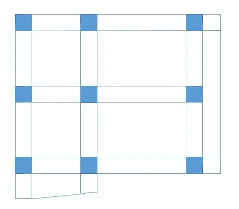
Issues identified in the framing plan:
Indirect lateral load transfer in both X and Y directions :- Some beams are connected to other beams instead of columns making it ineffective to lateral load transfer, this also leads to heavy shear force in the primary beam and thus making it prone to shear failure.
Eccentricity :- The longer the distance between center of mass and center of stiffness, the higher the torsional moment of the buidling. In the given plan the building is subjected high torsional moment in both X and Y directions.
Possibility of strong beam weak column:- The sizes of the columns mentioned are mostly 25x25cm, the beam sections are mentioned as 50cm. Therefore inertia of beam will be higher than that of column. To counteract this issue it is recommended that reinforcement in the columns should be adequately higher than that of beams and avoid collapse of the columns.
Solution:
The beams can all be rearranged and connected to columns and providing cantilevers beyond the system of symmetrical columns.
3)
Observations:
Floor plan:
- The floor plan is neither uniform or symmetric casuing the lateral loads introduced to not have 100% inflluence in the same direction, therefore a special lateral load resisting system for these torsional moments mmust be accomadated.
Random Internal columns:
- The lateral load will not be transfered efficiently due to the presence of random internal columns, therefore desirable building response is not achieved. So the columns must be assumed and designed only for gravity loads.
Floor to Floor variation in Partition walls and beams:
- Partition walls provide important mass control in buildings, beams play vital role in shear transfer from floor to beam. All these elements are not in order leading to heavy distortion in distribution of lateral loads.
Suggestions:
- Heavy torsional forces can be controlled by respective lateral load system. Therefore corner shear walls are suggested.
- Corner shear walls should be heavier on the left due to the proportion of floor area being greater on left side.
- Corner shear walls shall be preferrable supported by box foundation.
- Corner shear walls can be connected by link beams to transfer shear between them.
- The internal columns shall be supported by isolateed footings and connected with the shear walls through tie beams.