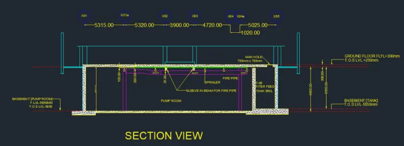
Creating Kitchen layout, Hatching of Architectural elements and sectional view of an Industrial Building in AutoCad
1) AIM:
- To create Kitchen layout the given kitchen layout.
PROCEDURE:
STEP 1:
- The Default setting is et to Metric system.
- Units are given as Decimal and precision is set to 0.0.
STEP 2 :
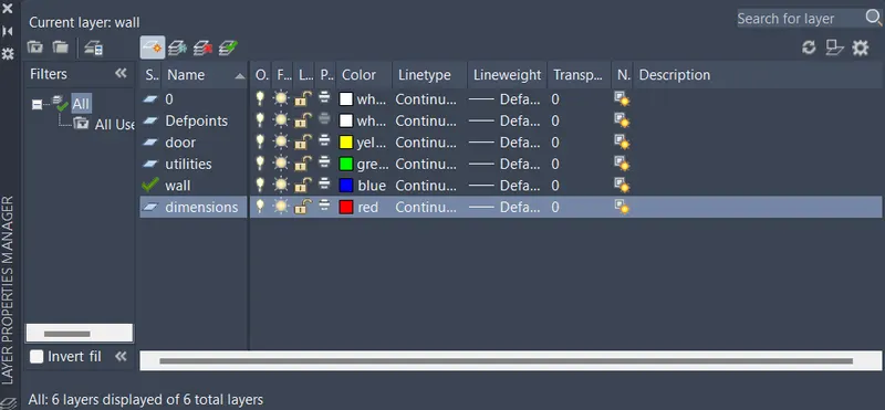
- Layer Properties manager is opened from Layer panel and required layers are created.
STEP 3:
The commands used for creating the Walls, kitchen components, doors and windows are:
- LINE
- PLINE
- RECTANGULAR
- OFFSET
- TRIM
- CIRCLE
STEP 4:
- It is then hatched using HATCH command.
- Solid hatch and ANSI 32 are the hatches provided.
- The components of the drawing are all placed in their respective layers from Layer properties manager.
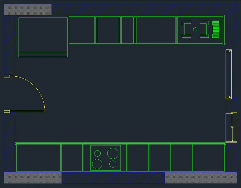
STEP 6:
- The walls, doors and windows are copied and placed using COPY command.
- The rest of the components are drawn using same commands mentioned in STEP 3.
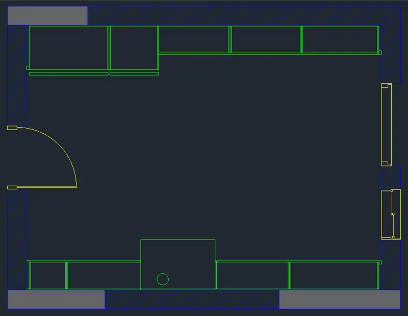
STEP 8:
- The layer is now set to dimensions in the Layer properties manager.
- Text is provided wherever necessary using MTEXT and DTEXT commands.
- Text style dialogue box is used to edit the text style.
- DIMLINEAR command is used to provide a dimension.
- The dimension style is editted from the Dimension Style manager giving DIMSTYLE command.
- DIMCONTINUE is used to give rest of the dimensions.
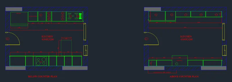
- Both the drawings are then dimensioned.
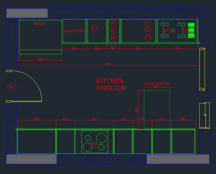
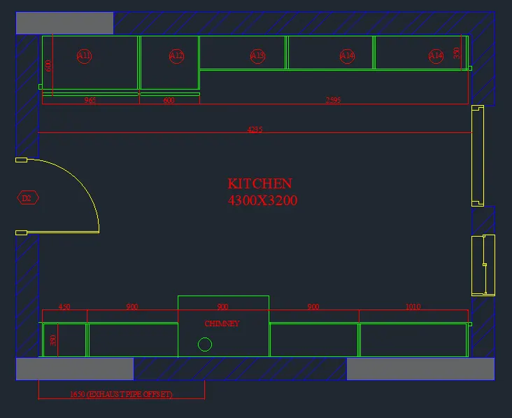
FINAL RESULT:
The required Kitchen layout is drawn.
2) AIM:
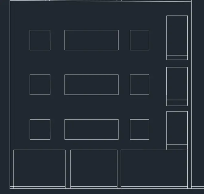
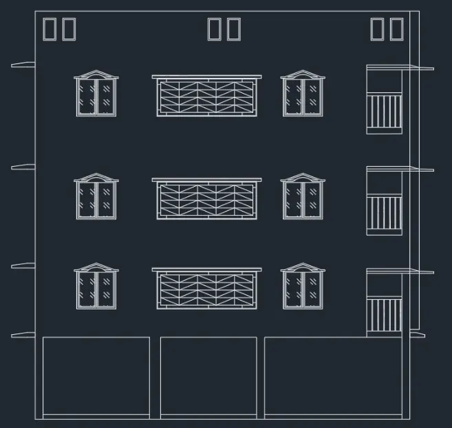
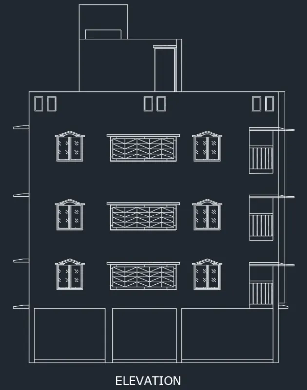
- To create the elevation of the plan created in the Challenges 7 and apply proper hatch in the walls, doors,
windows, and other architectural elements.
PROCEDURE:
STEP 1:
- Projections for the elevation from the plan and section is given using XLINE command.
- Therefore the doors, windows and parking space are created as per the dimensions.
- The rest of the lines are trimmed off using TRIM.
STEP 2:
- The window designs are then done using ARC,PLINE, LINE, OFFSET and HATCH command.
- The Gost_glass hatch is provided.
- The design is then copied and pasted on the rest of the windows using COPY command.
- The balcony is done using LINE, OFFSET and TRIM commands.
- It is also copied and pasted to all the floors using COPY.
STEP 3:
- The overhead tank is then created using LINE command.
- Using DTEXT command the text is provided.
FINAL RESULT:
The required elevation of the building has been created.
3) AIM:
- To create the section view of an industrial building as shown in Figure.
- Provide appropriate hatches and dimensions wherever required.
PROCEDURE:
- XLINE command is used to drawn construction lines.
- OFFSET command is used to get the outline of the drawing.
- The rest of the lines are trimmed off using TRIM.
- Then LINE command is used to complete the outline of the drawing.
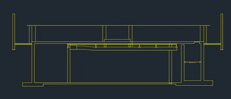
- The drawing is dimensioned using DIMLINEAR and DIMCONTINUE commands.
- The dimension style is edited using DIMSTYLE command.
- The text is provided using MTEXT and DTEXT commands wherever required.
- The size of the text is changed from properties.
- The linetype is also changed from properties by selecting the required line.
- HATCH command is used to provide the hatch.
- The componets of the drawing are then added to the respective layers usinng Layer properties manager in the Layer panel.
FINAL RESULT:
The section view of an industrial building is created as shown in Figure. Appropriate hatches and
dimensions wherever required are provided.