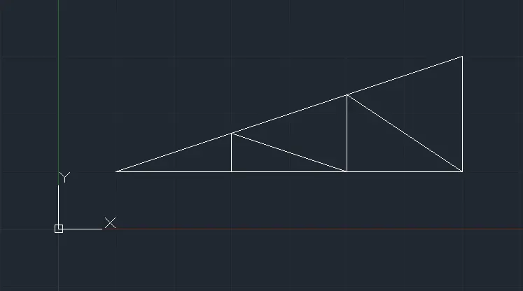
Creation of geometries by Coordinate system methods using AutoCad
Aim:
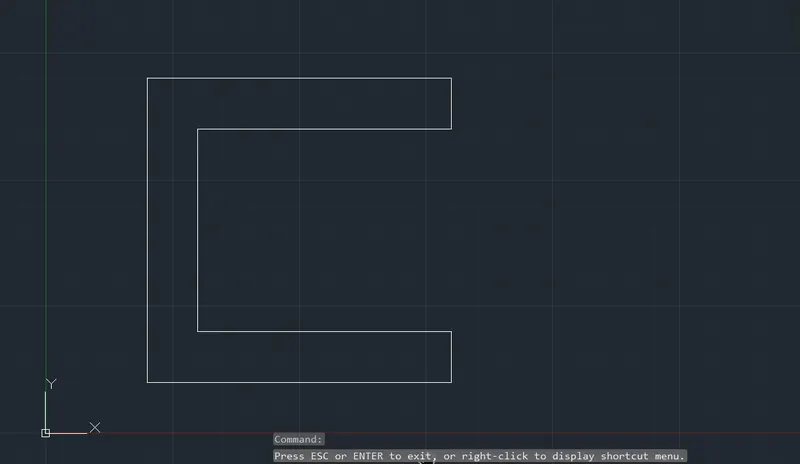
To create the geometries from P1 to P2 using all the coordinates system methods using the Line tool to create the geometries.
Imperial template and decimal units must be used for drafting.
Introduction:
The coordinate systems methods are :
- Absolute coordinate system.
- Relative coordinate system - Relative rectangular coordinates; Relative polar coordinates.
- Direct distance entry.
Procedure for the methods are given below.
Absolute coordinate system:
Absolute coordinate entry is the default. Absolute coordinate entry always counts from the origin. When drawing lines, AutoCAD is ready to place the next vertex wherever you tell it to go:
- Type L on the command line and press enter
- Type required coordinates on the command line and press enter. The first point is created.
- Then the next point needs to be specified according to the cartesian coordinates system.
- The line is drawn from the first point to specifed second point.
- Press enter to finish the Line command.
Relative coordinate system:
For relative coordinates, AutoCAD does not count from 0,0. Instead, the reference point is the previous point in the drawing. Let’s draw another line, and see what it looks like compared to the old one:
Relative rectangular coordinates:
- Type L on the command line and press enter
- Type the first point on the command line and press enter
- Type @ followed by required units from the first point on the command line and press enter.
- In this method once the point is specified, it is considered as origin fof the next line and the coordinates must be given considering previous point as 0,0.
- Press enter to finish the line command.
Relative polar coordinates:
Polar coordinates are named for their “pole”; the reference point to start counting from, which is similar in concept to the origin. Polar coordinates employ one radial distance and one angle (by convention, the angle is measured counterclockwise from the x-axis). The angle signifies the direction, and the distance is how far to go in that direction from the pole.
- Type L on the command line and press enter
- Type required first point on the command line and press enter, this is now the origin of the next point.
- Type for example @5<60 on the command line and press enter. The @5 is distance of the next point and <60 denotes the angle.
- Press enter to finish the line command.
P1, P2 created using all the Coordinate system methods.
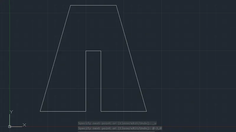
P3
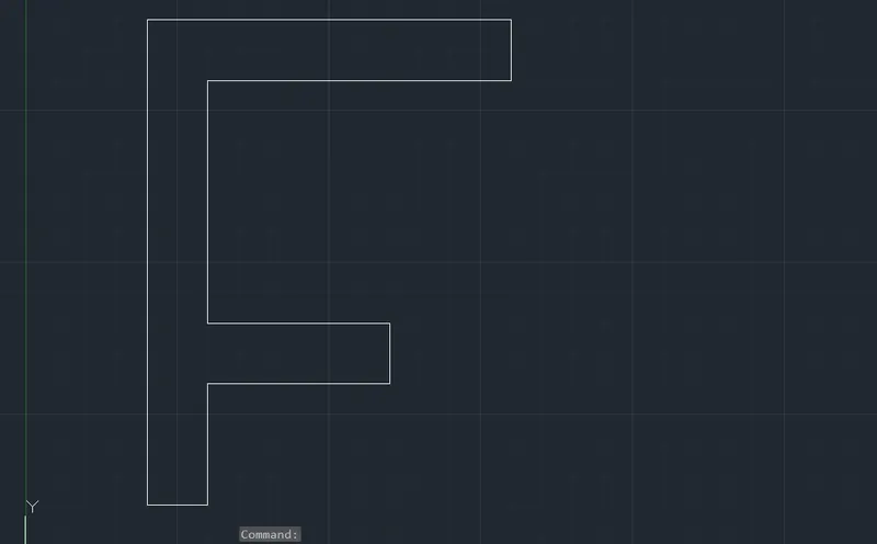
P4
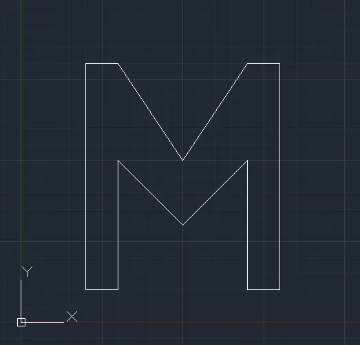
P5
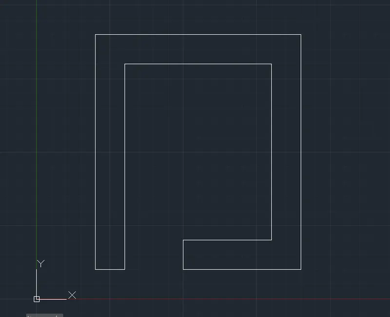
P6
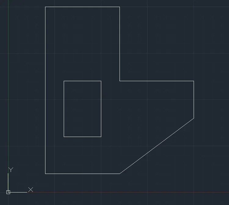
P7
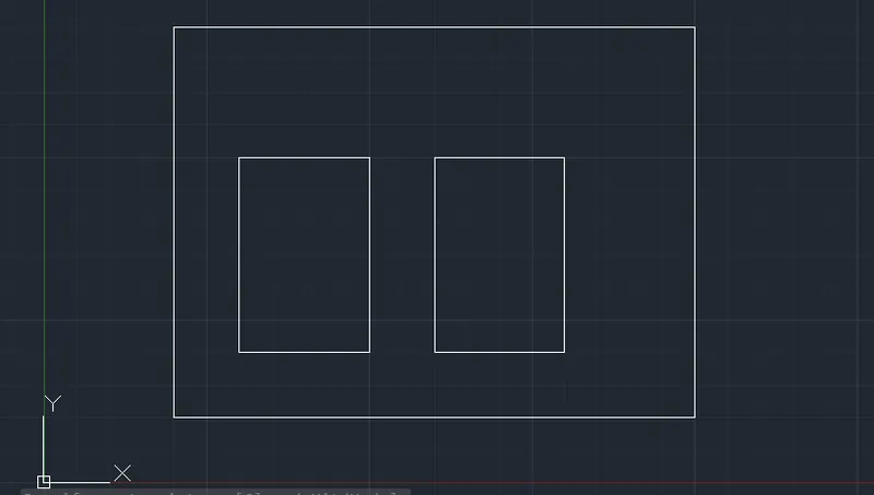
P8
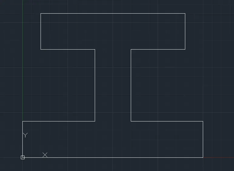
P9
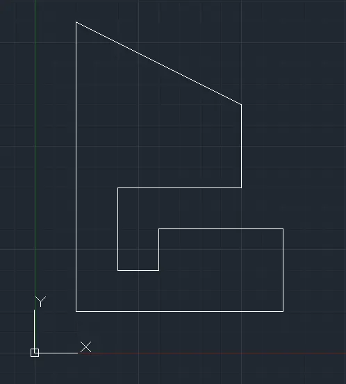
P10
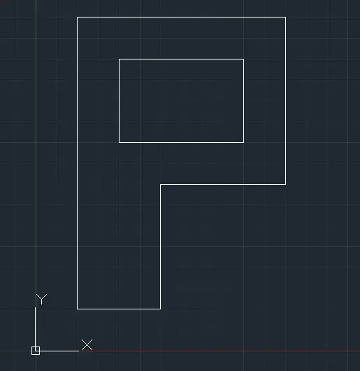
Civil related problems:
Aim:
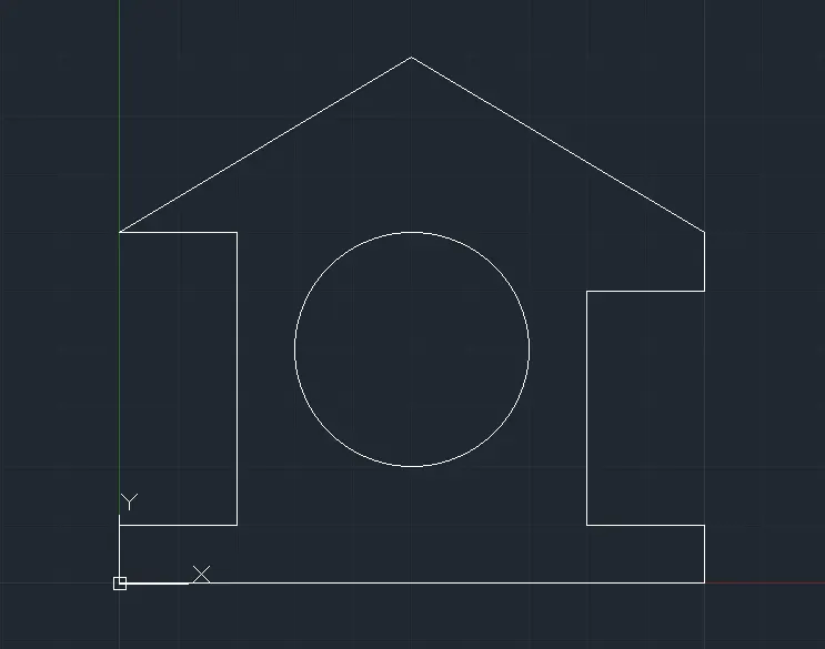
To draw the profile and the trusses using any coordinate system method.
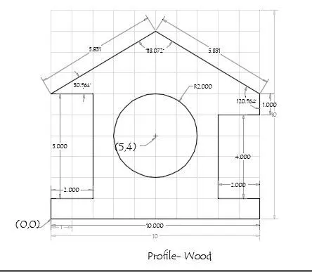
Procedure:
- The line command is used for drawing.
- For straight lines Relative rectangular coordinate system was used.
- For the diagonal lines Relative polar tracking method was used.
- For the circle the center, radius method was used.
Profile:
Truss 1:
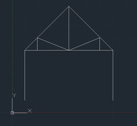
Truss 2:
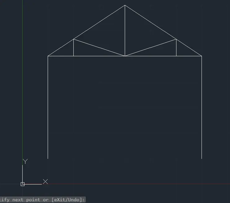
Truss 3:
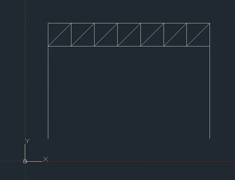
Truss 4: