Drafting of various geometries using Chamfer, Fillet tool in AutoCad
Aim :
To draw the given Geometries as per given dimensions using tools and commands learned in AutoCAD software.
Drawing 1:
Procedure:
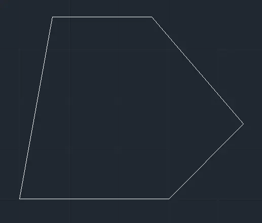
- Decimal unit of measurement is chosen as per instructions.
- The outline is first drawn using PLINE command and Direct entry method.
- For the angles in the outline the Relative polar coordinate system method is used.
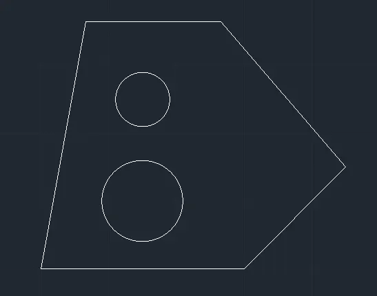
- The centres of the circles are then marked using the LINE tool for getting accurate distance.
- Using endpoint of the line as center the circles are drawn using Centre,Radius method.
- The lines are then erased using ERASE.
Drawing 2:
Procedure:
- Architectural unit of measurement is chosen as per instructions.
- The outline is first drawn using PLINE command and Direct entry method.
- For the angles in the outline the Polar tracking is switched on and the Increment angle is set at 45,90 135....
Drawing 3:
Procedure:
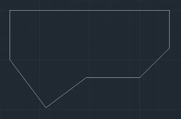
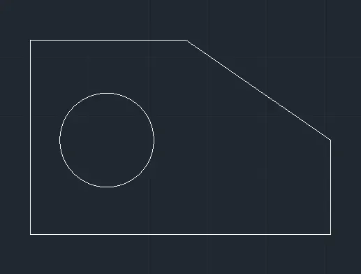
- Engineering unit of measurement is chosen as per instructions.
- The outline is first drawn using PLINE command and Direct entry method.
- The straight lines are drawn as per dimensions provided and the diagram is closed forming the required angle in the diagonal.
- The centre point of the circle is calculated and using Center, Radius method the circle is drawn.
Drawing 4:
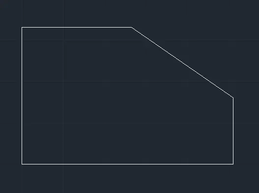
Procedure :
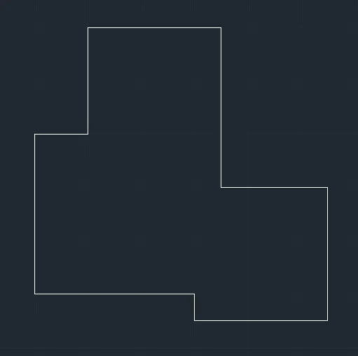
- The geometry is drawn using PLINE command and Direct entry method.
Drawing 5:
Procedure:
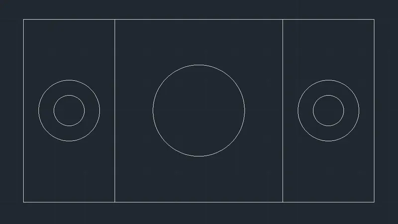
- The outline is first drawn using RECTANGULAR command and dimensions of the rectangles.
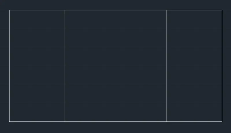
- In Object snap dialogue box the Geometric center check box is ticked.
- Using the Geometric center of the rectangles as the center and the provided Diameters the circles are drawn using Center, Diameter method.
Drawing 6:
Procedure:
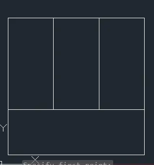
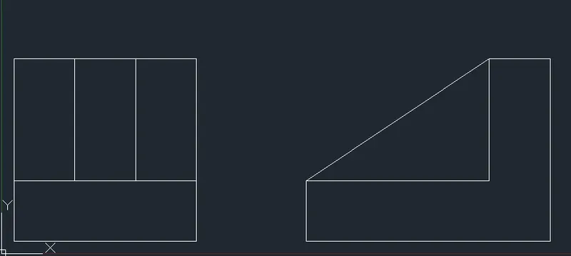
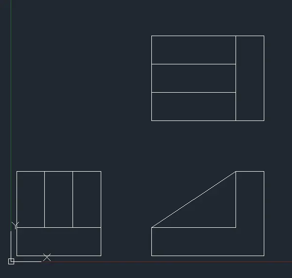
- The first rectangle using RECTANGULAR command.
- Then it is split according to the given dimensions using LINE tool.
- The next diagram is drawn using PLINE command.
- The geometry of straight lines are fisrt drawn to scale and then the diagonal line is joined by snapping the endpoints.
- The next diagram is drawn as the same as the first using RECTANGULAR tool and lines to split them.
Drawing 7:
Procedure:
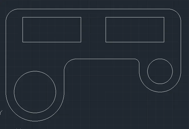
- Lines are drawn using PLINE tool and then filleted according to provided radius using FILLET command.
- The rectangles are drawn using RECTANGULAR command and placed in the given dimensions within the outline.
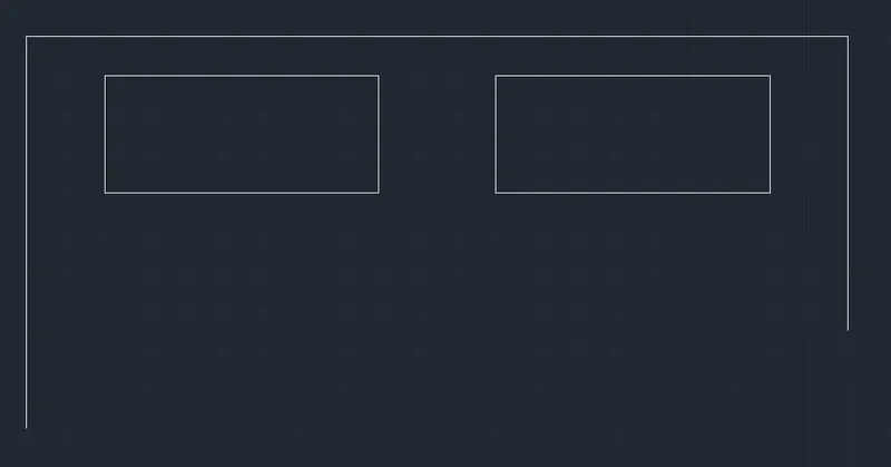
- The center required for the circle is arrived using line command and the midpoint of the line is turned on using OSNAP.
- CIRCLE command is used and Center,radius method is used for drawing the circles with given diameters and radius.
- Using the TRIM tool and the line the outer circle is trimmed to form and arc and the line is erased.
- The same procedure is used for the other side and the lines are filetted using FILLET to complete the drawing.
Drawing 8:
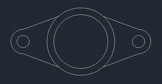
Procedure:
- A line is drawn using LINE command to act as center point for two circles.
- The circles are drawn using CIRCLE command and Center , Radius method.
- Lines cutting the circle through the middle vertically are drawn and TRIM command is used to trim off the circle to form arcs.
Drawing 9:
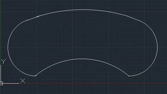
Procedure:
- A line is drawn using LINE command to act as center point for two circles.
- The circles are drawn using CIRCLE command and Center , Radius method.
- Lines cutting the circle through the middle vertically are drawn and TRIM command is used to trim off the circle to form arcs.
- They are then placed together to form the figure.
Drawing 10:
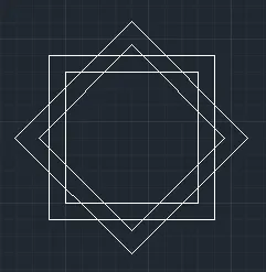
Procedure:
- A square is created using RECTANGULAR command.
- The square is offsetted using OFFSET tool.
- It is then copied using COPY tool.
- It is rotated by using polar tracking and ROTATE to get uniform angle.
- It is then moved using MOVE tool to the same center point as the first square.
Drawing 11:
Procedure:
- Using PLINE tool and Direct entry method the outline is drawn.
- The top line is then offseted using OFFSET command to form as baseline for the angles.
- The two angled lines are then created and moved using MOVE and placed on the created lines with the help of OSNAP.
- A square is created in the given points and then it is rotated using ROTATE and polar tracking to complete the diagram.
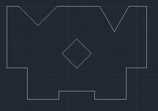
Result:
The above diagrams were created using various Tools and commands in the AutoCAD software according to the dimensions and instructions provided in the drawings.