Creating Architectural and Structural model with 3D rendering using REVIT
1)
The Type of structure that has been chosen is b. Office building.
2)
- The assumed location is Chennai, Tamil Nadu.
- The Type of Structure selected is Type 2.
Modelling Requirements as per NBC for office building:
- Open spaces around the building should not be less than 4.5m.
- The width of road abutting the building is taken as 9m.
Floor Area Ratio:
- Floor Area Ratio (FAR) for type 2 construction building is 2.9.
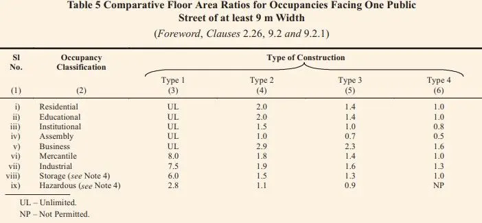
Calculating FAR for current Project:
Total area of building:- 32m x 29m = 928 m^2
Plot size:- 50m x 50m = 2500 m^2
Floor Area Ratio (FAR) = Total area of the building / plot size
therefore,
The FAR of the current project is less than 2.9 and within NBC limits.
3)
AIM:
- To use the structural model and include the following components based on the type of structure selected
a. Foundation – Isolated / Wall/Matt Foundation
b. Columns
c. Beams Connected to Columns
d. Roof Framing/ Truss
e. Floor / Decks
f. Floor Openings for Elevators and Stairs
PROCEDURE:
STEP 1:
- Open a structural model in Revit, select File-> New-> Project and open a structural template.
- Save the file as Project2 Structural from File-> Save as-> Project.
STEP 2:
- Open an Elevation view and create levels as required using Levels option from Datum panel in Architecture tab.
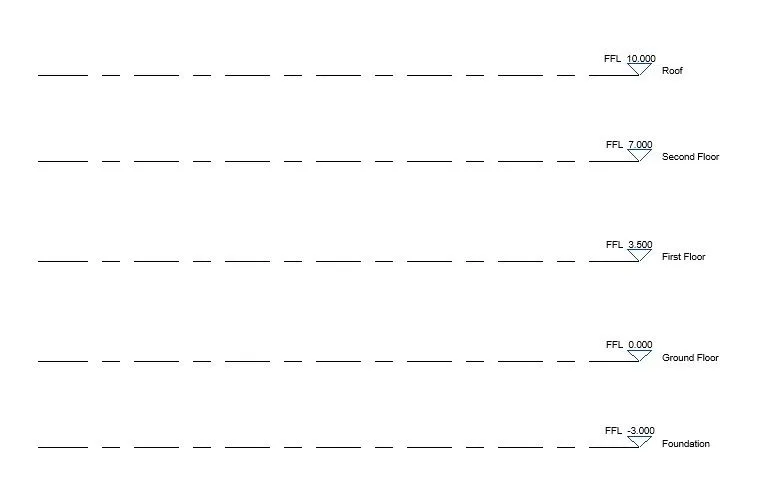
- Open Ground floor plan from FLoor plans in Project Browser.
- Create the grids as required using Grids option from Datum panel in Architecture tab.
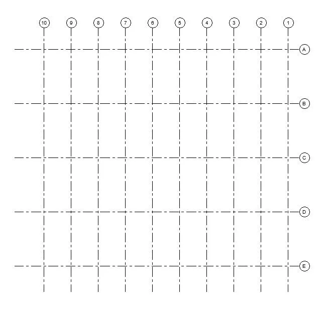
STEP 3:
- Create Isolated footings at every Grid intersection using Structure Tab-> Foundation-> Isolated.
- Select At grids option and select all the grids.
- Delete the footings that will not be required according to the design.
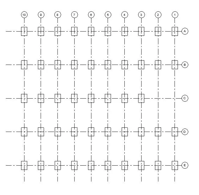
STEP 4:
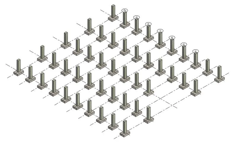
- To create Columns Select Structure-> Column.
- Select the required column type from Property browser.
- Set Base constraint as foundation and Top constraint as Ground floor.
- Use At grids option and select all grids to place the columns and delete the ones that are not necessary according to design.
STEP 5:
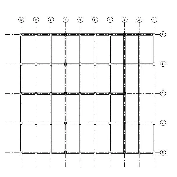
- To create Beams select Structure-> Beam.
- Select the type of beam from the Property browser and set the constraints as required.
- Connect the beams to the columns and place them where required.
STEP 6:
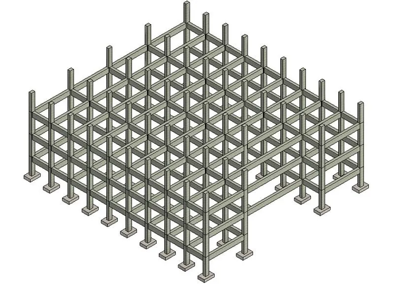
- The columns and beams from Ground Floor are copied and select Paste-> Aligned to selected levels.
- Select the First Floor and Second Floor levels and the components are copied.
STEP 7:
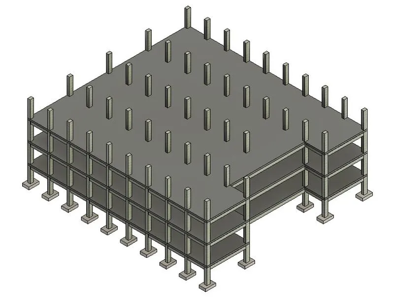
- To create floor Select Structural Tab-> Floor-> Floor structural.
- Select Ground Floor plan and draw the boundary line as required and click finish.
- Go to 3d View select the floor and copy it.
- Select Paste-> Aligned to selected levels.
- Select the First Floor and Second Floor levels and the components are copied.
STEP 8:
- To create a Shaft opening for the stairs Select Architecture tab-> Opening Panel-> Shaft.
- Use Rectangle tool in Draw menu and create the opening as required.
- Base constraint is set to Ground Floor level and Top constraint is set to Second Floor Level with a Top offset.
- Shaft for stairs is created.
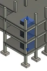
STEP 9:
- To create Truss Select Structure Tab-> Truss.
- Draw the boundary of the Truss conneccting the columns in the Roof level.
- Set the constraints appropriately and the truss is created.
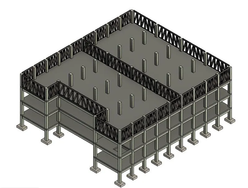
FINAL RESULT:
The following components have been included in the structural model succesfully.
a. Foundation – Isolated / Wall/Matt Foundation
b. Columns
c. Beams Connected to Columns
d. Roof Framing/ Truss
e. Floor / Decks
f. Floor Openings for Elevators and Stairs
4)
AIM:
- To use the architectural model andinclude the following components based on the type of structure selected
a. Wall Layout with appropriate material and finishing
b. Exterior façade with fancy finish
c. Interior partition walls to size rooms
d. Components to add details to a room ( Desk, Chair, Lighting, Plumbing fixtures)
e. Add components such as stairs Elevators
f. Have at-least one side of the building with curtain walls and glass panels
g. Include interior and exterior lighting fixtures
h. Place proper topographic components from outside ( Trees, Parking, Plants) to add details to the model.
PROCEDURE:
STEP 1:
- Open an Architectural model in Revit, select File-> New-> Project and open an Architectural template.
- Save the File as Project2 Architectural from File-> Save as-> Project.
STEP 2:
- Select Manage tab-> Manage links and Add the Project2 Strutural model.
- Select Collaborate tab-> Copy/Monitor-> Select link and select the copied link.
- Copy all of its components using Multiple option and Click finish.
STEP 3:
- To begin working on the model in the Architetcural template first hide the linked Structural model using VG command.
- Select Architecture Tab-> Wall to create wall layout.
- Select the wall and in the Property browser click on Edit type to edit the wall as required.
- To add curtain wall select the wall and change it to curtain wall from Property browser.
- Using an Interior Partition wall type a partition wall is created to seperate and size the rooms.
- Similarly to the edit parameters of the wall select wall and click on Edit type in the property browser.
- Then add doors and windows from Architecture tab wherever necessary.
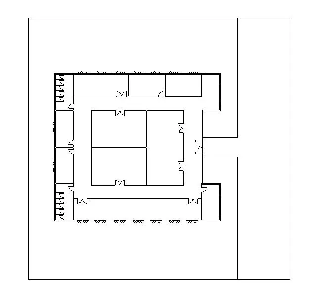
STEP 4:
- To add the components to the rooms Select Architecture tab-> Components-> Place a component and select the component from the Property browser.
- To load components from Revit library select Insert tab-> Load family and select the required family from Revit library and select Ok.
- The loaded component family can be found and used in Property browser.
- Therefore appropriate components required by rooms are added to the model.
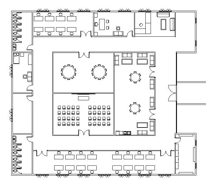
- Select a component and right click. Click on Select all instances-> Visible in view.
- Once all of them are selected click on Copy and then Paste-> Aligned to selected levels.
- Select First floor and Second floor levels to copy the components to every floor.
STEP 5:
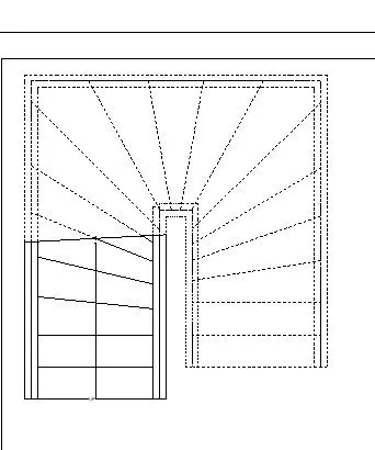
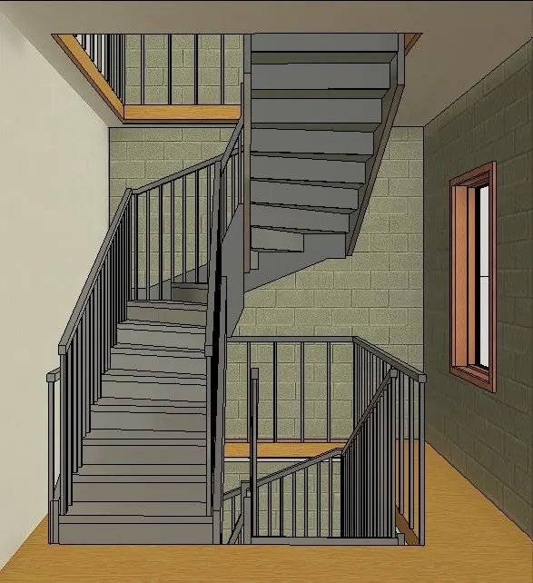
- To add stairs Select Architecture Tab-> Stairs.
- The U shape winder is chosen and is placed on the shaft region.
- Once the stairs have been placed connecting Ground Floor to First floor select the Connect stairs option.
- Go to an appropriate view and select the Second Floor level.
- Stairs connecting all the levels have been created.
STEP 6:
- To add lighting fixtures to the model Select Insert -> Load Family and load appropriate internal and external lighting fixtures from Revit Library
- Go to Ceiling Plans-> Ground Floor to create the ceiling, select Architecture tab-> Ceiling-> Sketch ceiling and using Line option sketch to create the ceiling.
- Select the ceiling and Copy-> Paste-> Aligned to selected levels and select the First floor and Second floor levels.
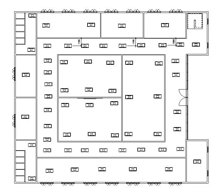
- Now select the Ground floor ceiling plan to place Interoir lighting fixtures.
- Select Architecture tab-> Components-> Place a component and choose the Lighting fixtures from Property browser.
- Place them wherever required in the Ground Floor ceiling Plan.
- After placing them in the Ground Floor select a lighting fixture and right click. Click on Select all instances-> Visible in view.
- Once all the lights are selected click on Copy and then Paste-> Aligned to selected levels.
- Select First floor and Second floor levels to copy the ligting fixtures to every level.
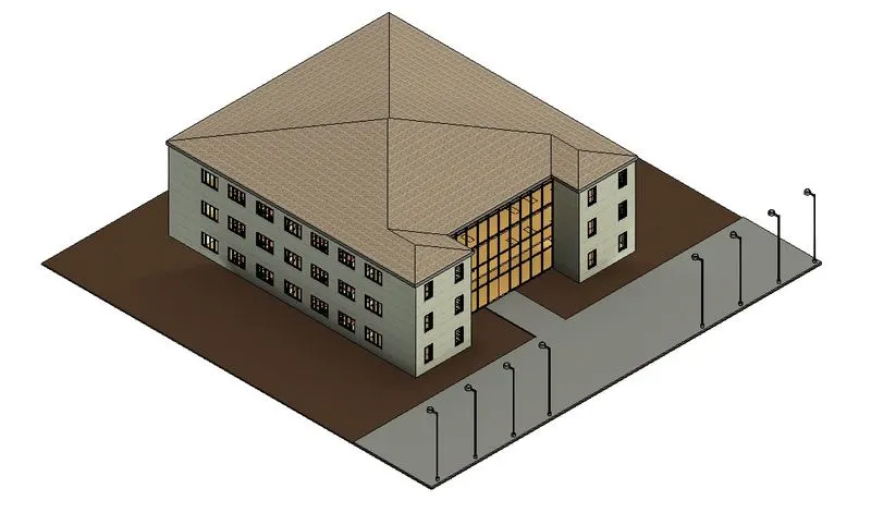
- To add exterioir lighting like Select Architecture tab-> Components-> Place a component.
- In the Property browser select approriate exterior lighting and place them in the model as required.
STEP 7:
- To place topographic components like Trees, Parking, Plants select Select Insert -> Load Family and load required topographic components
- Select Architecture tab-> Components-> Place a component and select the loaded components and place them wherever necessary.
- A pathway is created using Architecture tab-> Walls.
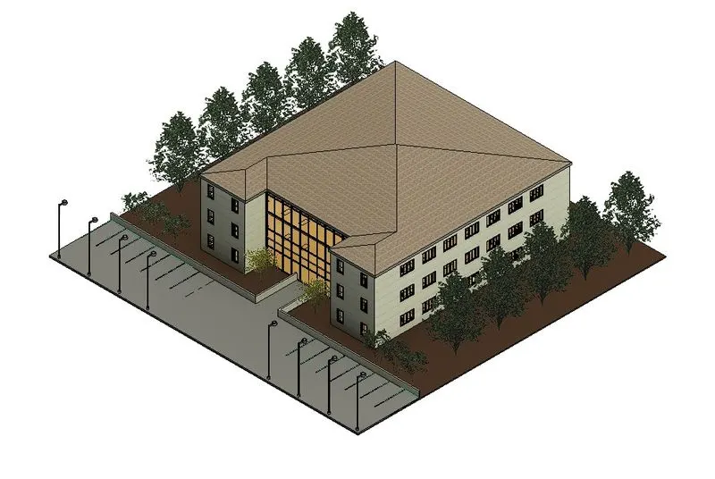
FINAL RESULT:
The following components have been included in Architecural model succesfully:
a. Wall Layout with appropriate material and finishing
b. Exterior façade with fancy finish
c. Interior partition walls to size rooms
d. Components to add details to a room ( Desk, Chair, Lighting, Plumbing fixtures)
e. Add components such as stairs Elevators
f. Have at-least one side of the building with curtain walls and glass panels
g. Include interior and exterior lighting fixtures
h. Place proper topographic components from outside ( Trees, Parking, Plants) to add details to the model.
5)
AIM:
- To Provide a set of drawings in an architectural and structural model to list the following details with categories and appropriate sheet templates included.
a. Floor Plans with Annotations
b. Elevations
c. Sections
PROCEDURE:
STEP 1:
- Open the Architectural model from File-> Open-> Project.
- Go to View tab-> Sheet to create a new sheet.
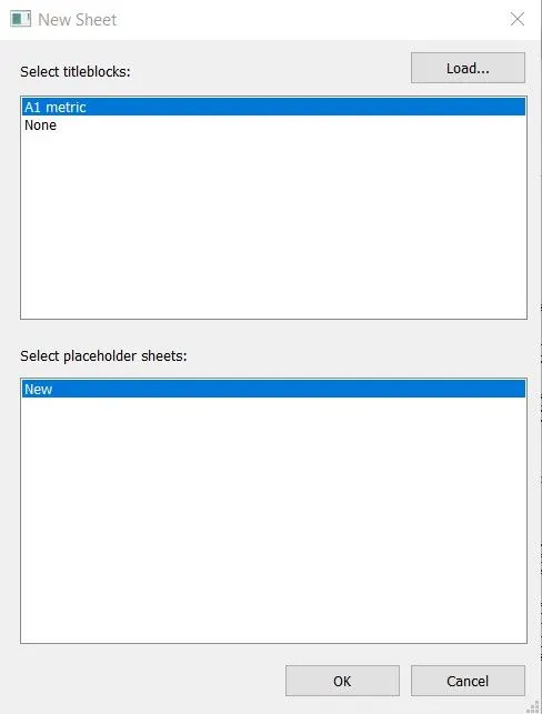
- Select required sheet and click Ok.
- Or load sheet from library if different size is required.
STEP 2:
- Once the sheet is opened, select the sheet and rename it from the Titleblock.
- Navigate to Floor plans-> Ground Floor plan in Project browser.
- Drag the Ground floor plan on to the sheet to paste it.
- The scale can be changed from property browser if necessary.
- Sheet containing Ground Floor plan is created and named appropriately.
- Similiarly repeat the process for the remaining Floor plans, Elevations and sections.
ARCHITECTURAL FLOOR PLANS:
A101 Ground Floor plan:
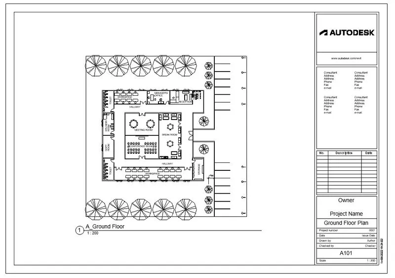
A102 First Floor Plan:
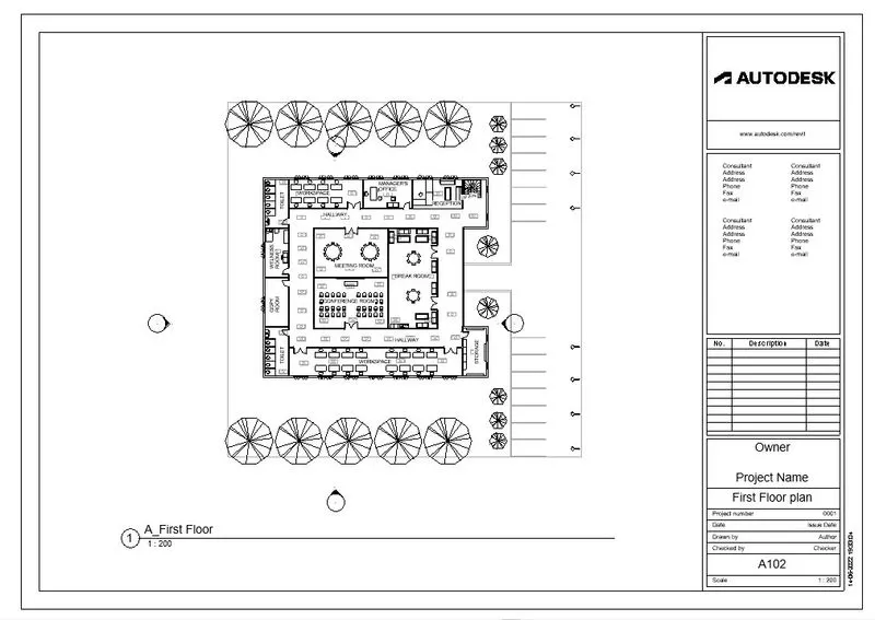
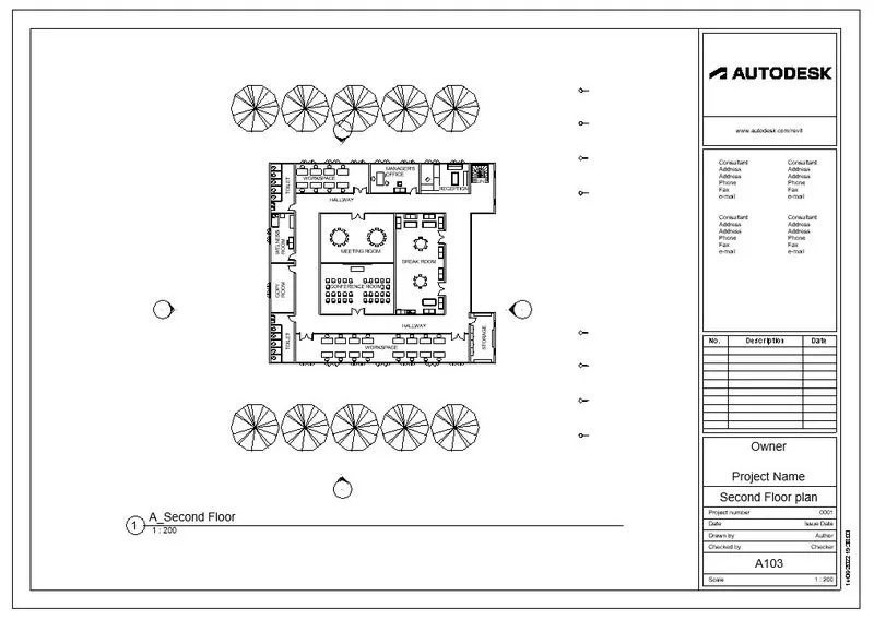
A103 Second Floor Plan:
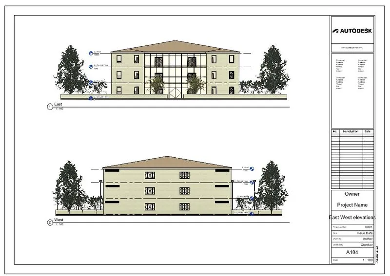
ARCHITECTURAL ELEVATIONS:
A104 East West elevations:
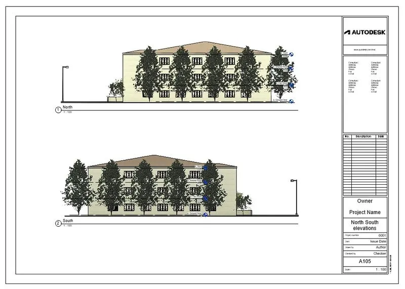
A105 North South Elevations:
ARCHITECTURAL SECTIONS:
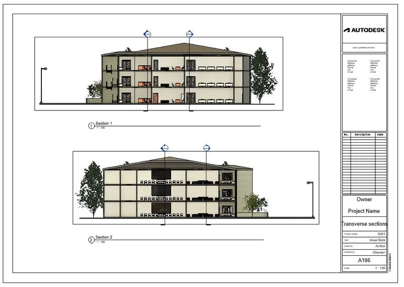
- To create a section go to a Floor plan from project browser.
- Select Section icon from Ribbon and draw section line wherever required.
- A section view is created.
A106 Transverse sections:
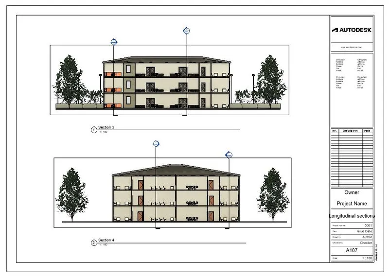
A107 Longitudinal Sections:
STEP 3:
- Open Structural model from File-> Open-> Project.
- The same process is repeated for creating Floor plans, Elevations and Sections in the structural model.
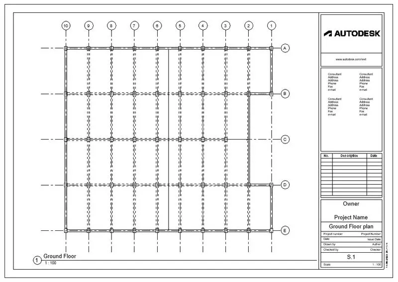
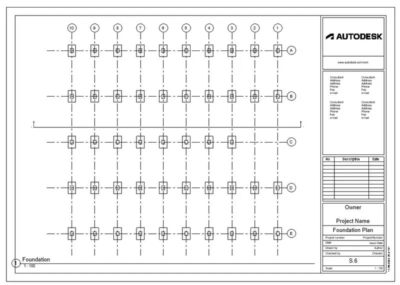
STRUCTURAL FLOOR PLANS:
S1 Ground Floor Plan:
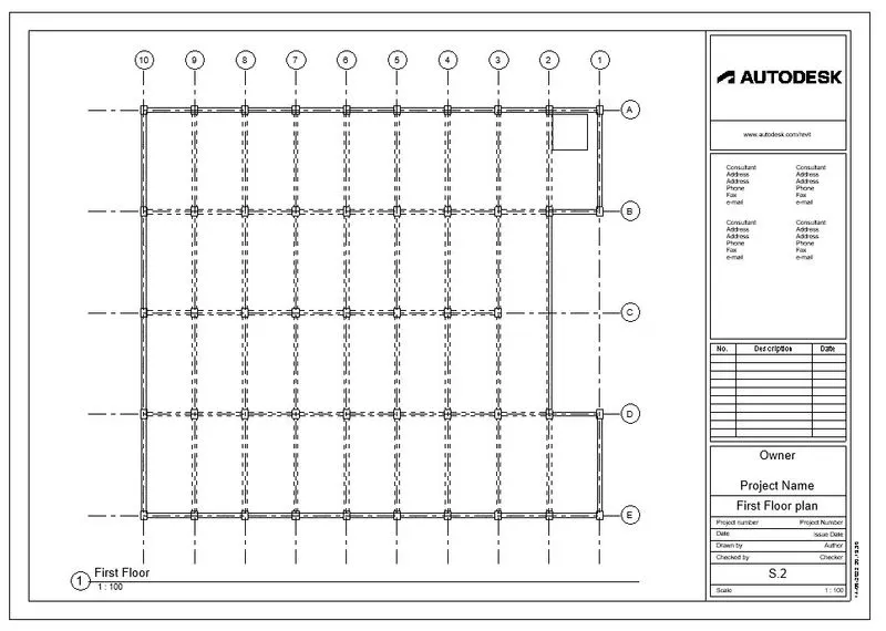
S2 First Floor Plan:
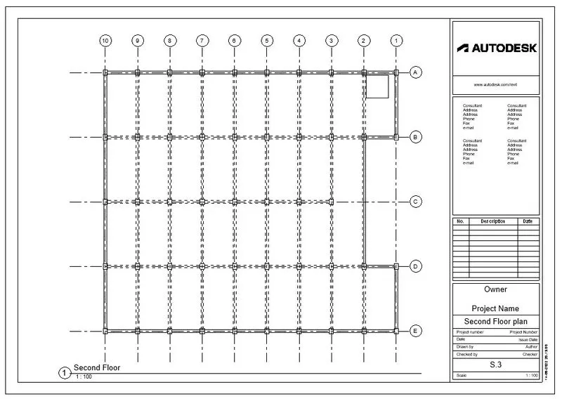
S3 Second Floor plan:
S6 Foundation Plan:
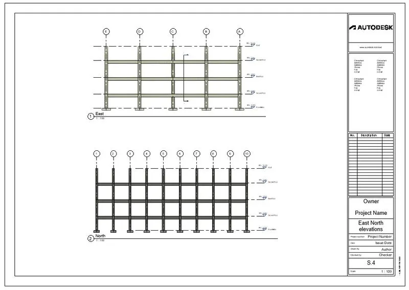
STRUCTUARL ELEVATIONS:
S4 East North Elevations:
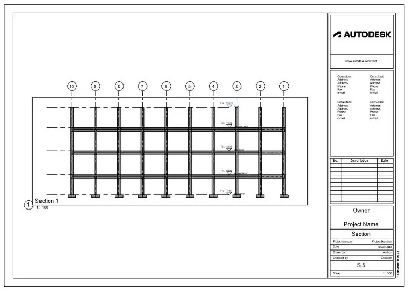
STRUCTURAL SECTIONS:
S5 Section 1:
FINAL RESULT:
A set of drawings has been created in an architectural and structural model to list the following details with categories and appropriate sheet templates included
a. Floor Plans with Annotations
b. Elevations
c. Sections.
6)
AIM:
- To use the Rendering settings, Render images of the 3D model produced and include the rendered images to the drawing sheets
a. Rendering from interior rooms
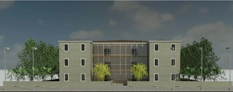
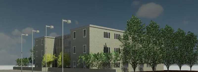
b. Rendering from out showing topographic features
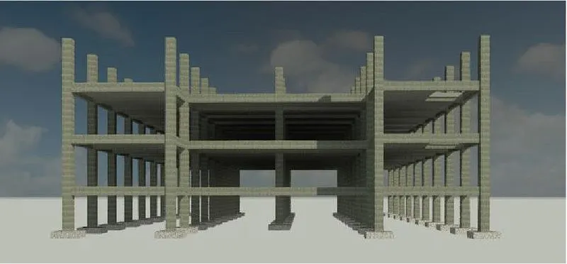
c. Rendering through structural framing
PROCEDURE:
STEP 1:
- Open the Architectural model from File-> Open-> Project.
- Go to 3D view dropdown-> Camera.
- Place the camera to get the required 3D views of the interior rooms and topographic features.
- Navigate to the created 3D views from the 3D views dropdown in Project browser and rename the views appropriately.
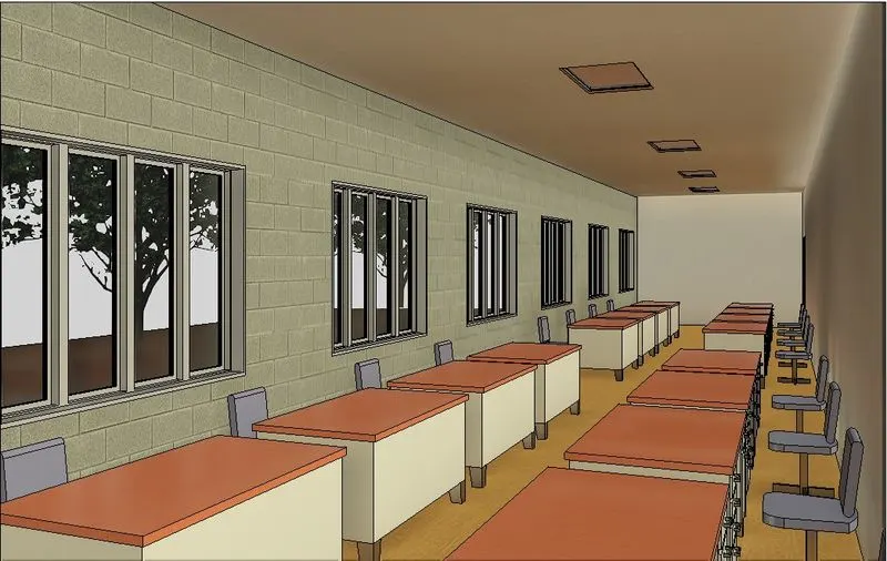
- Select and open 3D views and set the Visual style to Realistic.
STEP 2:
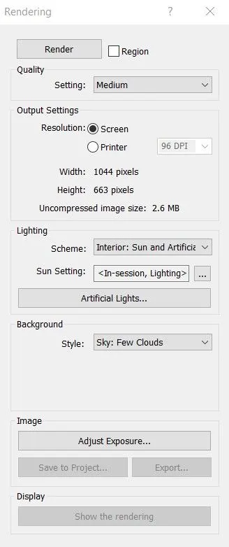
- Go to View tab-> Render.
- In the dialogue box set the Rendering settings as required and click on Render.
- Once the image is rendered click on Save to Project.
WORKSPACE:
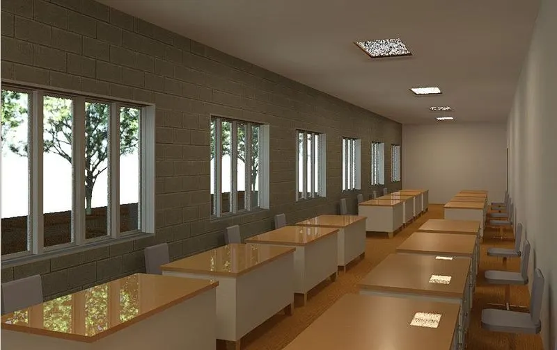
- Similiarly 3D views for all the Interior rooms, Topographical features and structural framing are created and Rendered.
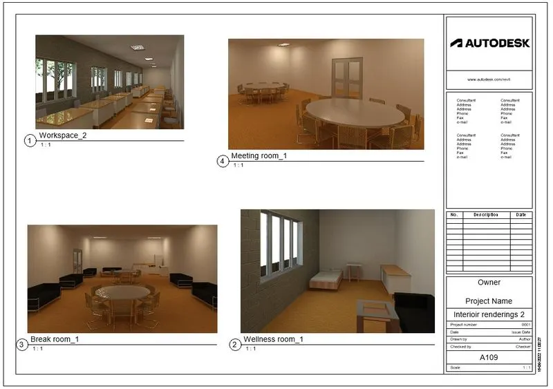
INTERIOR:
RECEPTION:
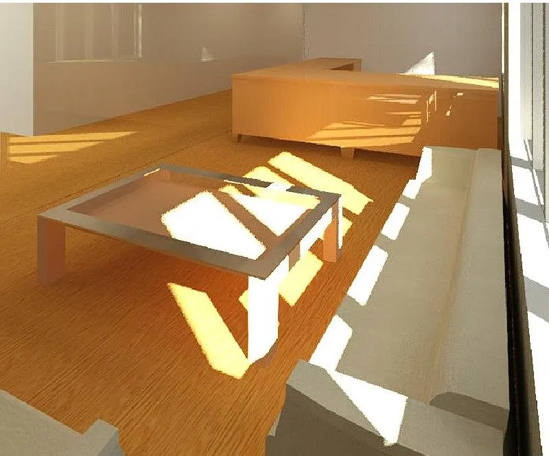
MANAGER'S OFFICE:
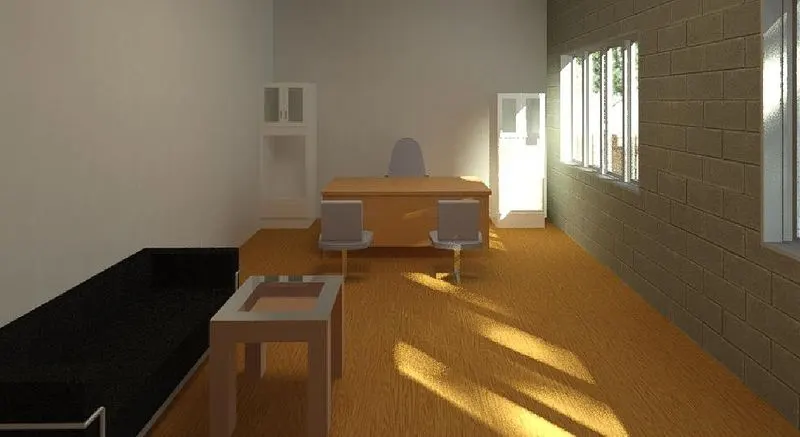
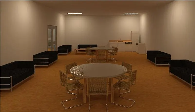
BREAK ROOM:
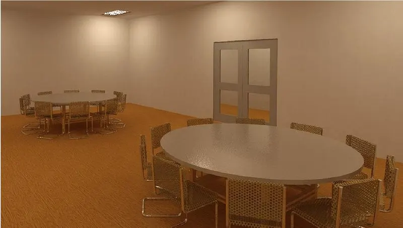
MEETING ROOM:
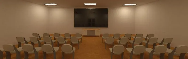
CONFERENCE ROOM:
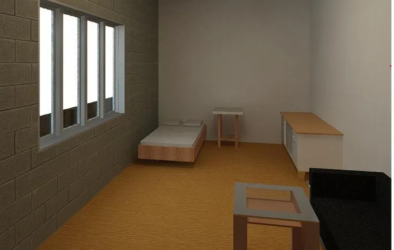
WELLNESS ROOM:
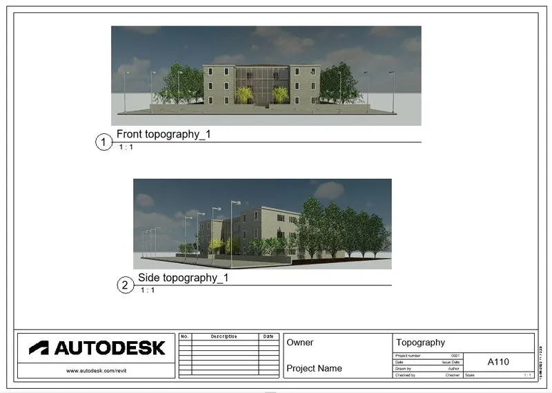
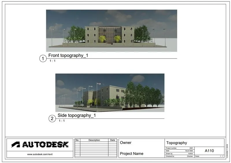
TOPOGRAPHY:
FRONT VIEW:
SIDE VIEW:
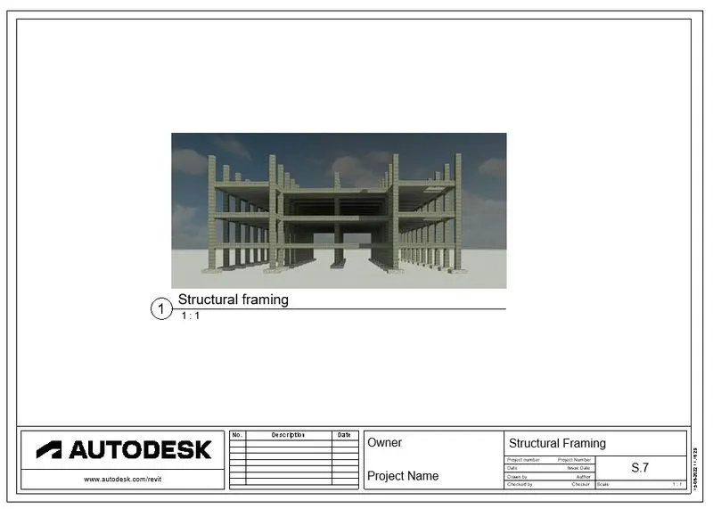
STRUTURAL FRAMING:
STEP 3:
- To add the rendered images into drawing sheets go to View tab-> Sheet.
- Select the sheet size or load required size from library.
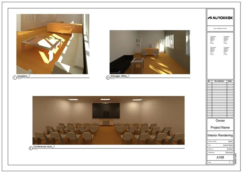
- Navigate to Renderings in the Project browser, drag them onto the sheet to place them.
- Sheets are created for all the renderings in the same process.
INTERIOR RENDERINGS 1:
INTERIOR RENDERINGS 2:
TOPOGRAPHY:
STRUCTURAL FRAMING:
FINAL RESULT:
The following rendering images:
a. Rendering from interior rooms
b. Rendering from out showing topographic features
c. Rendering through structural framing
have been created and added to sheets succesfully.
7)
AIM:
- To print the set of drawing sheets created and submit the drawings from the architecture and structure model.
PROCEDURE:
- Open the Architectural model from File-> Open-> Project.
- Navigate to Sheets in the Project browser.
- When the required sheet is opened type Ctrl+P.
- Print dialogue box is opened.
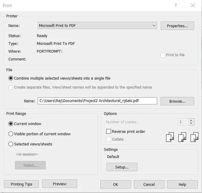
- Select Microsoft Print to Pdf in the dropdown and click on OK.
- Save the file to desired location.
- The drawing sheet is saved as Pdf.
- Similiarly all the drawing sheets that were created can be printed or saved as pdf using the same process.
FINAL RESULT:
It has been succesfully demostrated how to print or save the set of drawing sheets of the Architectural and Structural model created .