Modelling of 25 storey building with the specified properties using ETABS
AIM:
- To model a 25 storey building on ETABS with structural properties as specified.
- To check the translational fundamental natural period of vibration in both the x and y direction.
- To check if the following provision in Table 5 of IS 1893 (part 1) – 2016, on torsional irregularity satisfied.
- To check if the two provisions of clause 7 in Table 6 (shown in question) of IS 1893 (part 1) – 2016, regarding vertical irregularity is satisfied.
- To check if provision on inter-storey drift limitations in clause 7.11.1.1 satisfied.
SPECIFICATIONS:
- Ground floor or plinth floor level can be taken at a height of 1.5 metres from the base.
- Each of the successive 25 storeys has a storey height of 3 metres.
Structural Element Sizes
- Beams : 300 × 400 mm
- Columns : 800 × 800 mm
- Slab : 150 mm thick
Material Properties
- Grade of Concrete : M30
- Grade of Steel Reinforcement Bars : Fe 415
Loading
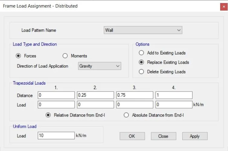
- Dead Load on beams from infill wall : 10 kN/m (Assume the same for roof floor in view of parapet)
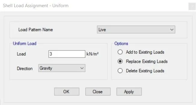
- Live load on floor : 3 kN/m2 (Assume the same for roof floor)
a) Buildings are assumed to be pinned at the base
b) All columns in all storey are of the same size
c) All beams in all storeys are of the same size
d) Building is located on Soil type-II and in Zone-III. Assume other factors if required.
PROCEDURE:
STEP 1:
- Open the Etabs software.
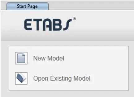
- In the Start page select New model option.
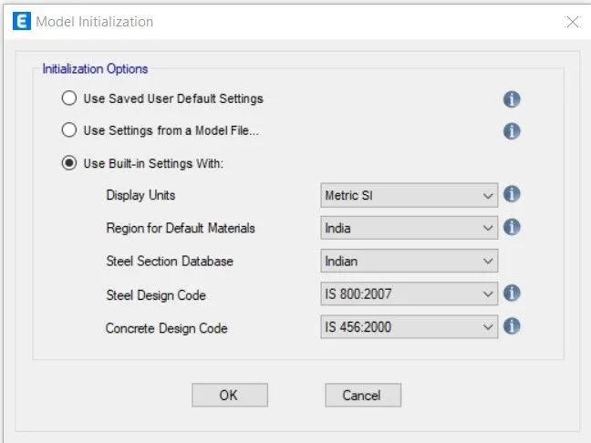
- In the dialogue box that appears select the Use built in settings option.
- Change all the required fields as follows.
- Click on OK.
STEP 2:
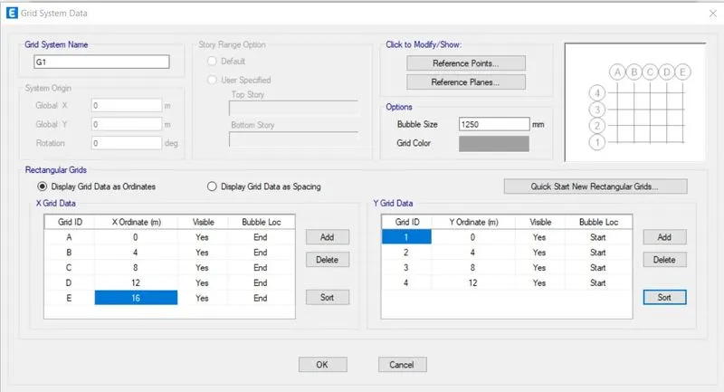
- In the dialogue box select Custom Grid spacing-> Edit Grid data.
- As per the specifications provide Grid data.
- Click on OK.
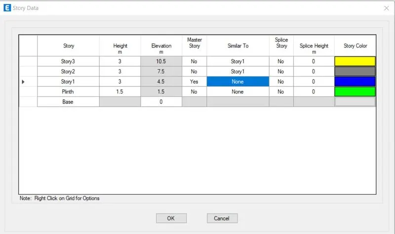
- In the dialogue box select Custom Story data-> Edit Story data.
- As per the specifications provide the height and elevations.
- Rename the stories as necessary.
- Set the Story 1 as master story.
- Set the other stories as Similiar to the Master story.
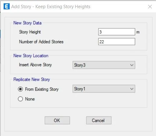
- To add another story select the top most story-> Add story-> Keep exiting story heights.
- Provide the required no. of stories.
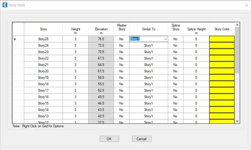
- Rename the stories as necessary.
- Set all the other stories as Similiar to the Master story.
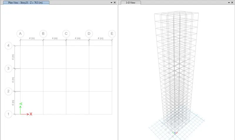
- The required model outline has been created.
STEP 3:
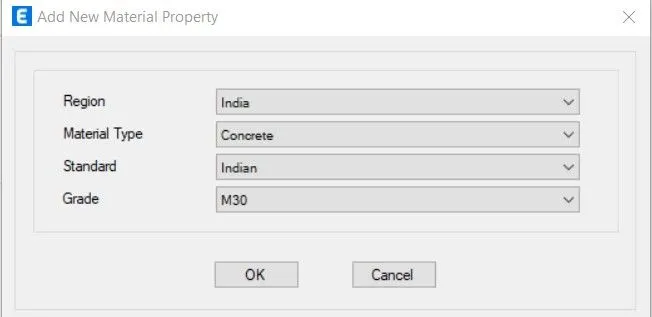
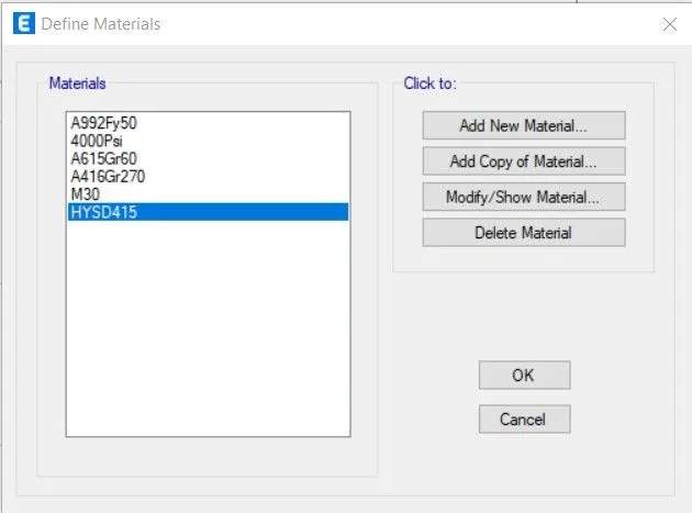
- To create the concrete material.
- Select Define-> Section Properties-> Frame sections.
- In the Define material dialogue box select Add new material option.
- Fill in the required fields as the following.
- Click on OK.
- Follow the same procedure to create rebar material.
- The required materials have been created.
STEP 4:
BEAMS:
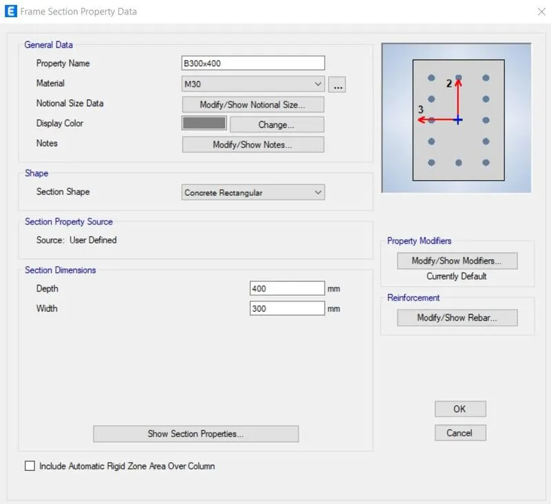
- To create the beams.
- Select Define-> Section Properties-> Frame sections.
- In the Define material dialogue box select Add new material option.
- Select Concrete rectangular option.
- Modify its properties as shown below.
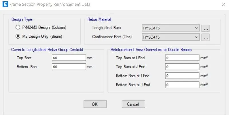
- Select the Modify/ Show rebar option.
- Modify its properties as shown below to create the beams.
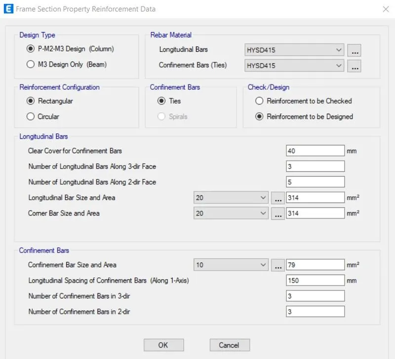
COLUMNS:
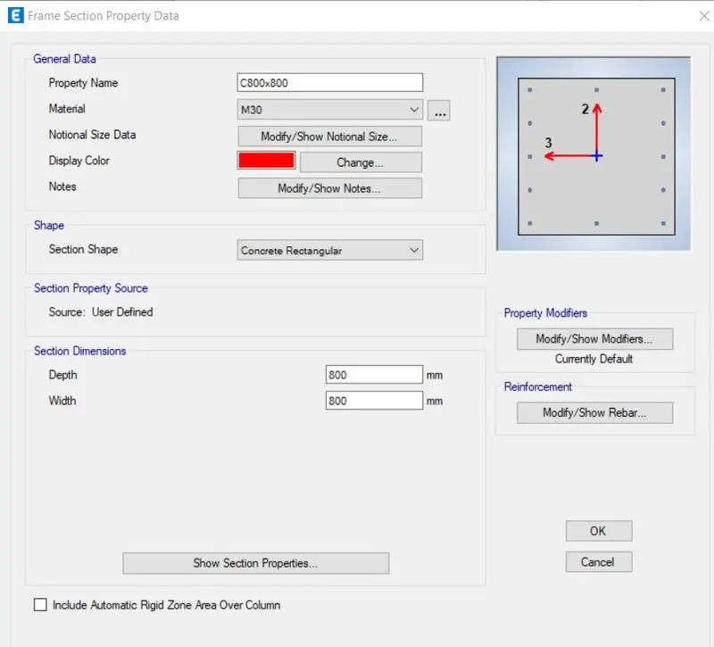
- To create the columns.
- Select Define-> Section Properties-> Frame sections.
- In the Define material dialogue box select Add new material option.
- Select Concrete rectangular option.
- Modify its properties as shown below.
- Select the Modify/ Show rebar option.
- Modify its properties as shown below to create the columns.
SLABS:
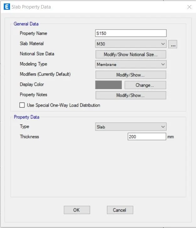
- To create the Slabs.
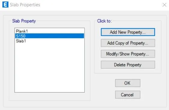
- Select Define-> Section Properties-> Slab sections.
- In the dialogue box that appears select add new property.
- Rename or change the required fields as shown below.
- Click on OK
- The required Slab property has been created.
STEP 5:
- Select Define-> Load patterns.
- Add the following Load patterns.
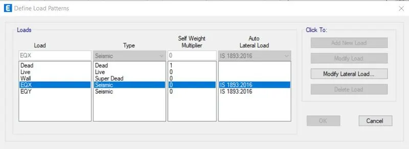
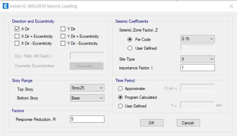
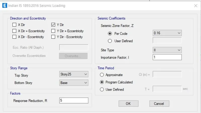
- For the loads EQX and EQY select Modify Lateral load.
- In Direction and Eccentricity panel check only X dir for EQX and uncheck the other boxes.
- Select only Y dir and unchech other boxes for EQY.
- Click on OK.
STEP 6:
- Select Define-> Mass Source.
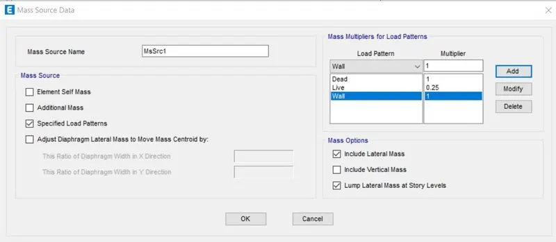
- In the dialogue box that appears select Modify Mass ource.
- In Mass source panel select SPecified load patterns and unselect others.
- Add the Load patterns and their multipliers as per Code as shown below.
- CLick on OK.
STEP 7:
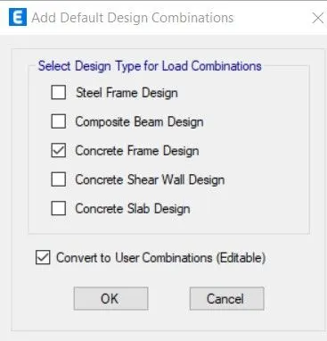
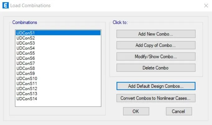
- To add load combinations select Define-> Load combinations-> Add default design combos.
- Check the Concrete Frame design box .
- Check the Convert to user combinaations box.
- Click on OK
- The Load combinations have been generated.
- Click on OK.
STEP 8:
MODELLING:
Columns:
- Using Quick Draw columns icon columns will be drawn.
- In the Properties of object window change the Property of the column to the created one.
- Set the Working plane as All stories.
- Place the columns on the grids.
Beams:
- Using Quick Draw beams icon beams will be drawn.
- In the Properties of object window change the Property of the beams to the created one.
- Set the Working plane as All stories.
- By selecting the grid lines the beams are automatically placed.
Slabs:
- Using Quick Draw Floors icon slabs will be drawn.
- In the Properties of object window change the Property of the Slab to the created one.
- Set the Plan view to the Master story and set Working plane to similiar stories .
- By selecting the grids the slabs are automatically placed within its boundaries.
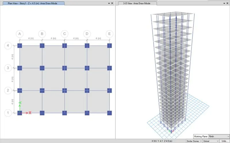
- The building has been modelled succesfully.
STEP 9:
- To assign loads to the frames go to Select-> Properties-> Frame sections.
- Select the created Beams.

- Go to Assign-> Frame loads-> Distributed
- Change the required fields as shown below.
- Click on APPLY and OK.
- To assign loads to the slabs go to Select-> Properties-> Slab sections.
- Select the created slabs.
- Go to Assign-> Shell loads-> Uniform
- Change the required fields as shown below.
- Click on APPLY and OK.
STEP 10:
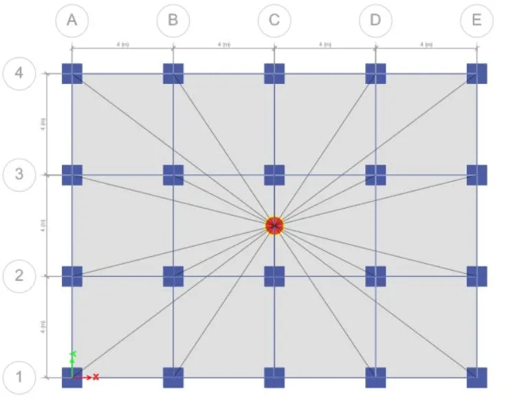
- To assign diaphragm selet Assign-> Shell-> Diaphragms-> D1.
- Click on APPLY and OK.
- The centre of mass is now automatically calculated.
STEP 11:
- Click on Save icon to save the file.
STEP 12:
- Once the model is saved click on Run analysis icon.
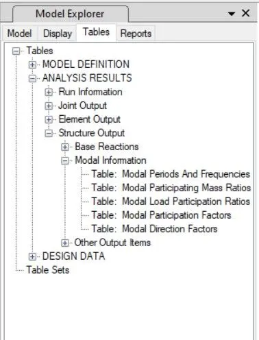
- Once the analysis is complete Navigate to the following and open the required tables to perform the verifications.
VERIFICATIONS:
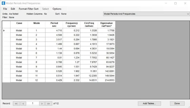
1) Check if the translational fundamental natural period of vibration in both the x and y direction is approximately: Tx1Tx1= 4.4 second Ty1Ty1= 4.2 second :- The resuts show major deviation therefore there is an error in modelling.
2) Check if the following provision in Table 5 of IS 1893 (part 1) – 2016, on torsional irregularity satisfied :- The results show that it is satisfied.
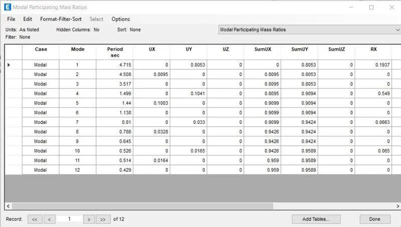
3) Check if the two provisions of clause 7 in Table 6 (shown below) of IS 1893 (part 1) – 2016, regarding vertical irregularity is satisfied :- The results show that the model satisfies the first provision of clause 7 in Table 6 of IS 1893 (part 1) – 2016, regarding vertical irregularity and does not satisfy the second provision .
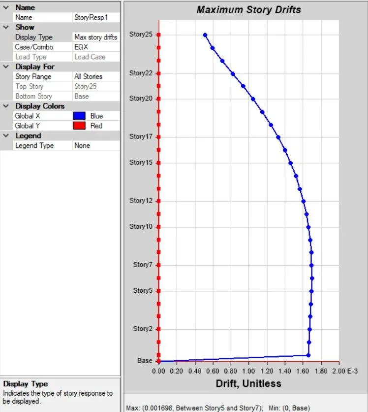
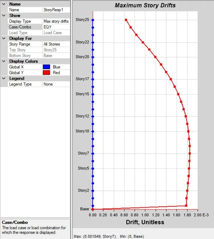
4) Check if provision on inter-storey drift limitations in clause 7.11.1.1 satisfied :- The results show that the model satisfies the inter-storey drift limitations in clause 7.11.1.1