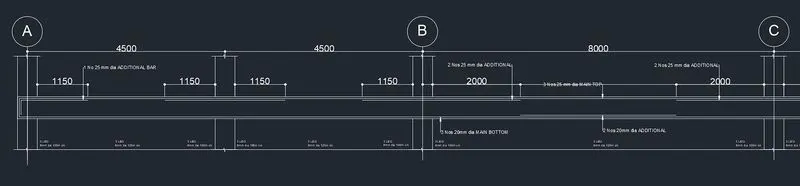
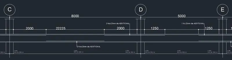
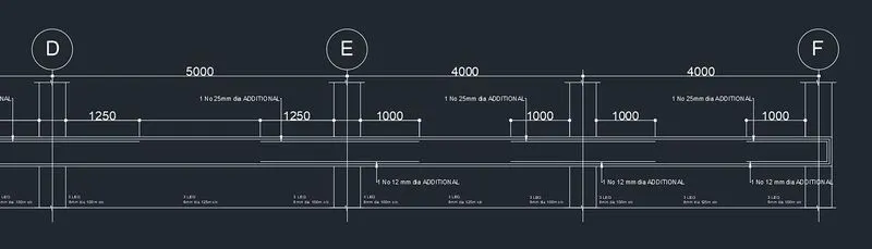
Reinforcement Detailing of Beams from ETABS output
AIM:
- To provide detail design of beams in Etabs.
- To provide reasons for failure of the middle span along grid A and provide solutions.
- To calculate value of the maximum shear force in any one of the spans in both the continuous beams, as per clause 6.3.3 (b) in IS 13920 – 2016.
Detailing Rule for any RC member:
Minimum longitudinal reinforcement as per IS-13920-2016 Clause 6.2.1 As=360mm^2
Minimum transverse reinforcement as per IS 456:2000 Clause 26.5.1.6 (Assuming 1000mm spacing in the formula) Asv=332mm^2
Development length as per IS 456:2000 clause 26.2.1 Ld= 41x dia of bar
PROCEDURE:
STEP 1:
- Open the provided ETabs file.
- Click on Run analysis icon.
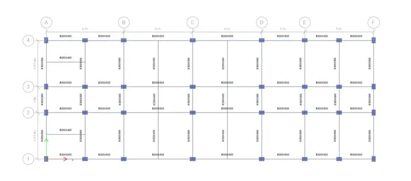
STEP 2:
- Click on concrete frame design icon.
- The longitudinal reinforcements and shear reinforcements for all the members have been designed.
- To toggle the view between longitudinal reinforcement and shear reinforcement click on Concrete frame design dropdown-> Display design Info-> Shear reinforcement.
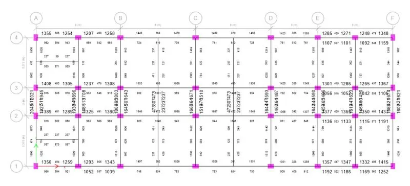
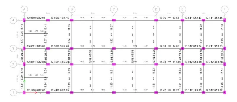
Reasons for Failure of the middle span along grid A and solution:
- The stress is above allowable value as per Codal requirement in this particular segment.
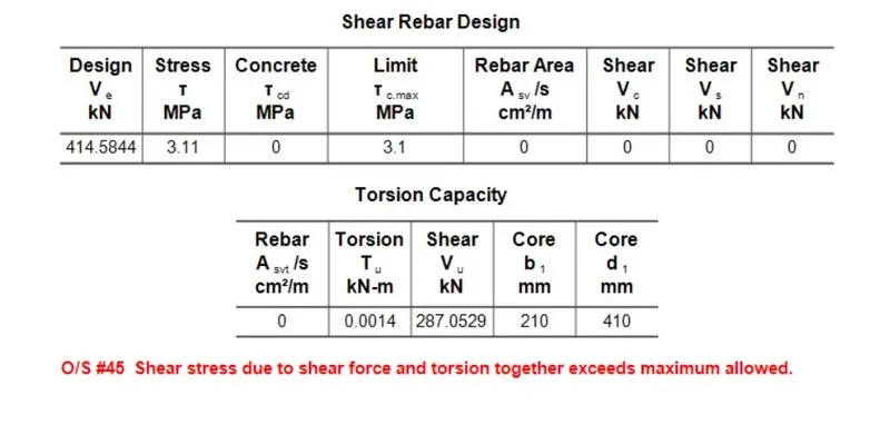
- Therefore the Shear stress capacity of the segment can be increased by changing the grade of concrete to one with higher Compressive strength for this particular beam.
STEP 3:
Sway shear force to the right:
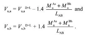
where,
Mas= 174 kNm
Mbh= 293 kNm
Lab= 4.725 m
Vd+l= 92 kN
Vu,a= 46kN; Vu,b= 230kN
Sway shear force to the left:
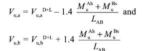
where,
Mah= 234 kNm
Mbs= 155 kNm
Lab= 4.725 m
Vd+l= 70 kN
Vu,a= 185kN; Vu,b= 45kN.
Details of longitudinal and shear reinforcement for 3 span continuous beam along grid A:
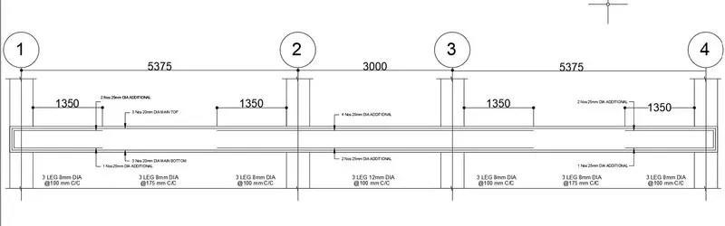
Details of longitudinal and shear reinforcement for 7 span continuous beam along grid 3: