Creating 3D Isometric view of various structural elements in AutoCAD
1)
AIM:
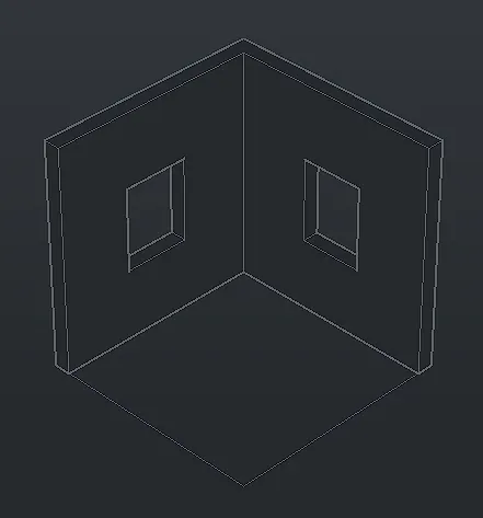
- To create a 3D Isometric View of the building with plan and elevation given.
PROCEDURE:
- AutoCAD is opened with Imperial setting as default.
- In units of measurement Engineering is selected.
- Precision is set to 0'-0.0".
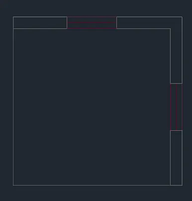
- Top view is selected in VIEW cube and plan is created with RECTANGULAR, TRIM, and OFFSET commands as per dimensions
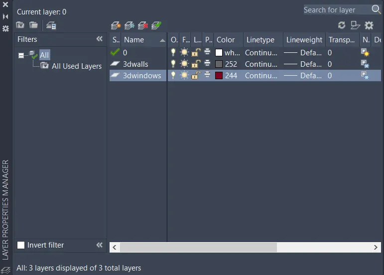
- Using Layer properties manager from Layer panel in Ribbon the required layers are created and the components are set to appropriate layers.
- In the View cube Home icon is clicked and the BOUNDARY command and region option is selected to make walls into regions.
- The walls are then extruded by EXTRUDE command to required height.
- Layer is set to window and the rectangle is moved in Z axis to required height using MOVE command.
- It is then extruded to using EXTRUDE.
- The walls are then filled by created rectangles in the gaps, making them into regions by REGION command and extruding them using Extrude option in Ribbon.
- The window is then selected and erased
- The remaining wall layers are joined using UNION command.
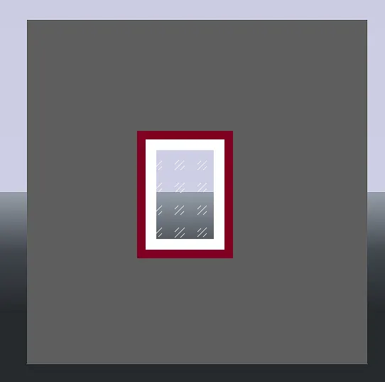
- Using View cube and UCS command the Elevation A is set to the XY plane.
- RECTANGULAR, OFFSET and LINE command is used to create window as per dimensions
- They are Hatched using HATCH command.
ELEVATION A
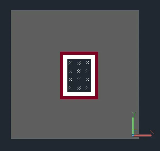
- Using View cube and UCS command the Elevation B is set to the XY plane.
- The window is created using the same method as in elevation A.
ELEVATION B
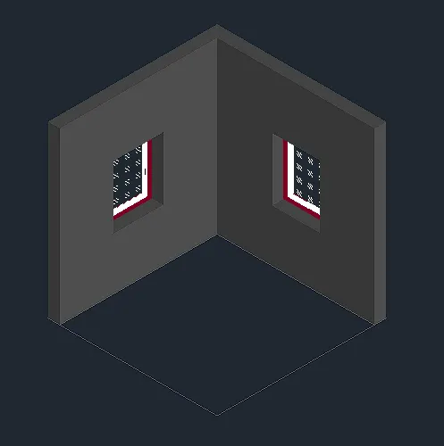
FINAL RESULT:
A 3D Isometric View of the building has been created with plan and elevation given.
2)
AIM:
- To create the 3D View of the Building Façade as given in the plan and elevation.
PROCEDURE:
- AutoCAD is opened with Imperial setting as default.
- In units of measurement Engineering is selected.
- Precision is set to 0'-0.0".
- Top view is selected in VIEW cube and plan is created with RECTANGULAR, TRIM, and OFFSET commands as per dimensions
- Using Layer properties manager from Layer panel in Ribbon the required layers are created and the components are set to appropriate layers.
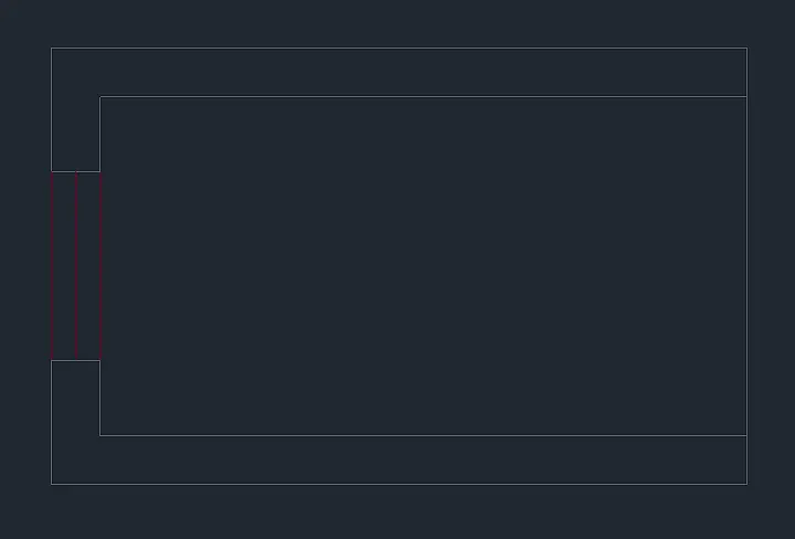
- In the View cube Home icon is clicked and the BOUNDARY command and region option is selected to make walls into regions.
- The walls are then extruded by EXTRUDE command to required height.
- Layer is set to window and the rectangle is moved in Z axis to required height using MOVE command.
- It is then extruded to using EXTRUDE.
- The walls are then filled by created rectangles in the gaps, making them into regions by REGION command and extruding them using Extrude option in Ribbon.
- The window is then selected and erased
- The remaining wall layers are joined using UNION command.
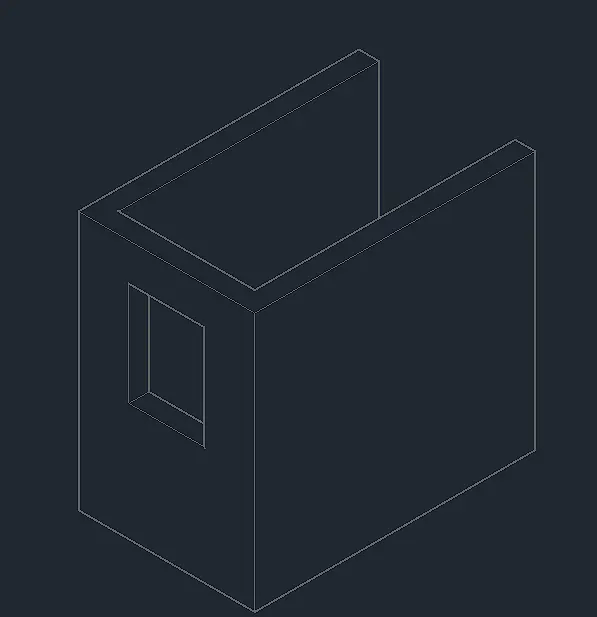
- Using View cube and UCS command the Elevation is set to the XY plane.
- RECTANGULAR, OFFSET and LINE command is used to create window as per dimensions
- They are Hatched using HATCH command.
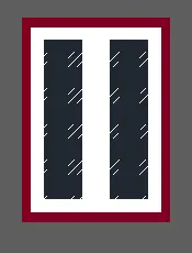
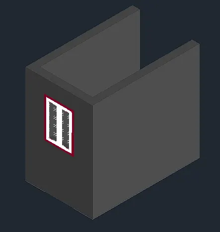
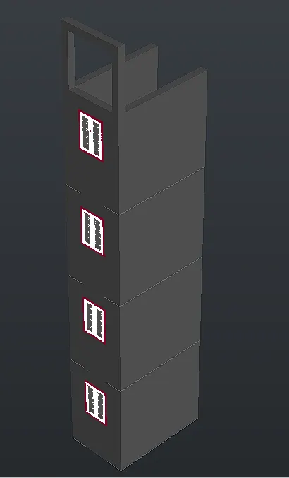
- The drawing is then copied 3 times using COPY command and is placed on top of each other.
- To get the column and beam on top a polyline is created on the required path using 3P command.
- A rectangle is created and EXTRUDE -> Path command is given and the polyline is selected to form the required structure.
FINAL RESULT:
The 3D View of the Building Façade as given in the plan and elevation is created.
3)
AIM:
- To create the isometric 3d view of a stair with railing as shown in the plan and elevation.
- Assume the size of the balustrades and the hand rails.
PROCEDURE:
- AutoCAD is opened with Imperial setting as default.
- In units of measurement Engineering is selected.
- Precision is set to 0'-0.0".
- In the Top view the Outline of the stairs are created as per dimensions with LINE, OFFSET, COPY and TRIM commands respectively.
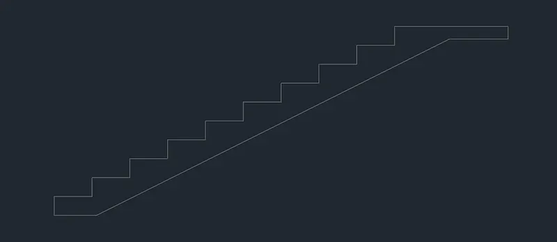
- Home icon is selected in the View cube.
- The plan of the stairs is rotated using ROTATE3D command.
- It is then created into a region using BOUNDARY command.
- It is extruded using EXTRUDE command as per dimensions.
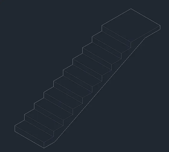
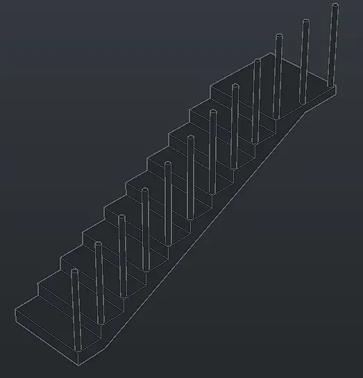
- UCS -> Face command is given, a tread is selected as the face.
- The balustrade is created by drawing a circle using CIRCLE command on the tread and Extruding it using EXTRUDE command as per dimensions.
- It is then copied and pasted on all the treads using COPY command.
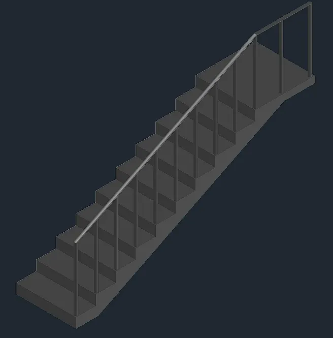
- A 3D polyline is drawn using 3P command as the path for the hand rail.
- A circle is drawn over the diameter of the balusrade and is extruded using the 3d polyline as the path by using EXTRUDE-> Path command to complete the hand rail.
FINAL RESULT:
The isometric 3d view of a stair is created with railing as shown in the plan and elevation.
4)
AIM:
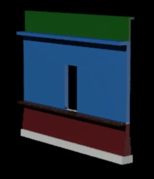
- To create the 3D view of a Wall with spread footing and door opening .
- To create a rendered view of the model with materials as of your choice.
PROCEDURE:
- UN command is given and Type is given to Decimal and precision is set to 0.0.
- In top view Section of the Spread footing is created using RECTANGULAR, LINE, OFFSET and TRIM commands.
- Home icon is given and the drawing is flipped 90 degrees in the x axis using ROTATE3D command.
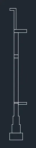
- The drawing is then converted into Regions by using BOUNDARY -> Region commands.
- Extrude icon is chosen from Ribbon, all the objects are selected and it is extruded as per the plan.
- From the Visual style dropdown shaded is selected and it is displayed.
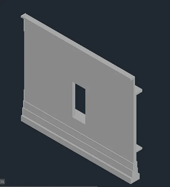
- MAT command is used to open the Material browser.
- The surface is chosen and Materials are assigned as per need.
- It is then displayed in the Realistic view from Visual styles manager dropdown.
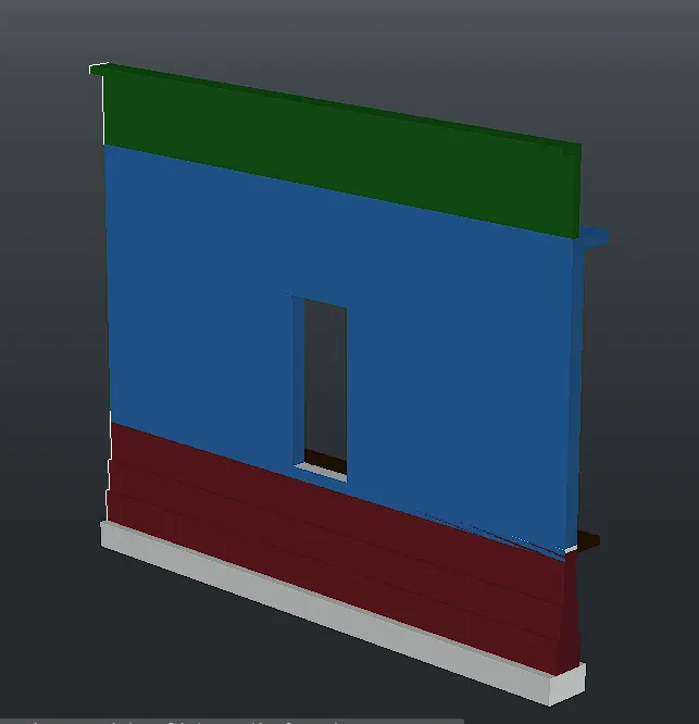
- RR command is given to render the drawing
FINAL RESULT:
The 3D view of a Wall with spread footing and door opening is created and rendered.