Creating a Floor plan, Footing detail and Isometric view using AutoCad
Aim:
To create the given drawings using various functions in AutoCAD and provide the detailed procedure for each drawing.
C1:
Procedure:
- Using RECTANGULAR command and end point the first rectangle is drawn.
- Using RECTANGULAR command and dimensions the other rectangles are drawn.
- They are then moved using MOVE command and placed on the required points.
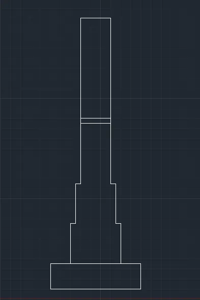
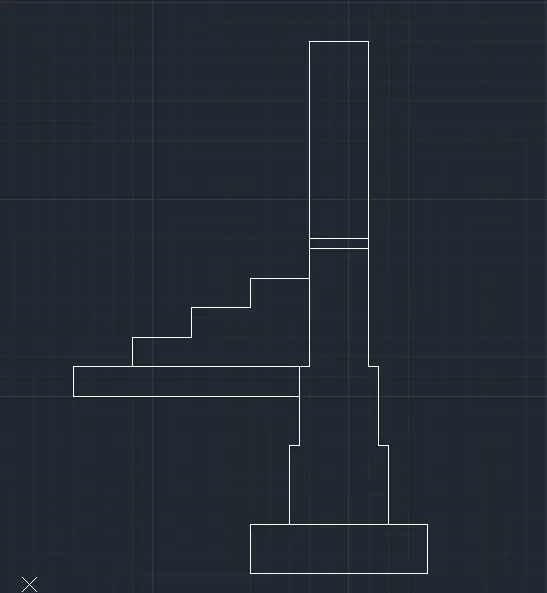
- The stairs are then drawn using PLINE command and Relative rectangular coordinates.
C2:
Procedure:
- Using PLINE command and Relative rectangular coordinates to measure distances the outline is drawn according to dimensions provided.
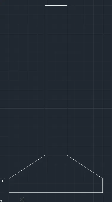
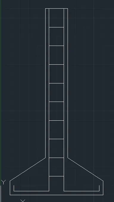
- Using RECTANGULAR command the first rectangle is drawn.
- It is then copied using COPY tool.
- As there are a number of the same rectangles present in the drawing ARRAY is used from the COPY command to create the rest of the rectangles.
- The reinforcement is then drawn using PLINE tool.
C3:
Procedure:
- The outline is created using PLINE tool and Relative rectangular coordinates according to provided dimensions.
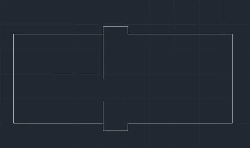
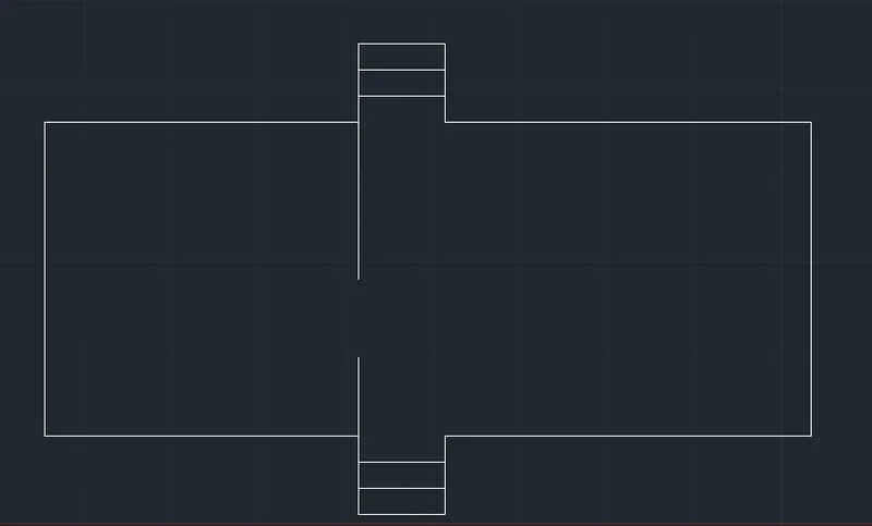
- The stairs are then drawn using RECTANGULAR command and provided dimensions.
- The drawing is then corrected using TRIM tool and trimming off unnecessary lines.
C4:
Procedure:
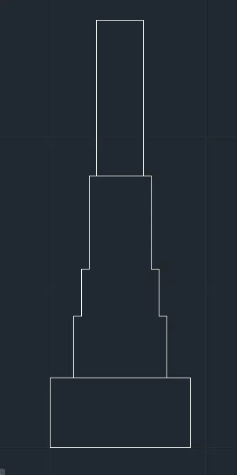
- Using RECTANGULAR command and end point the first rectangle is drawn.
- Using RECTANGULAR command and dimensions the other rectangles are drawn.
- They are then moved using MOVE command and placed on the required points.
C5:
Procedure:
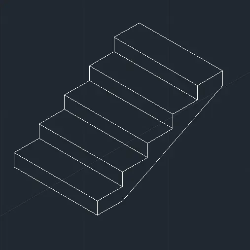
- First the ISODRAFT command is given to start isometric drafting.
- Ortho mode is switched on to maintain uniform angles.
- Then using Isoplane right and PLINE command the outline of the stairs is created.
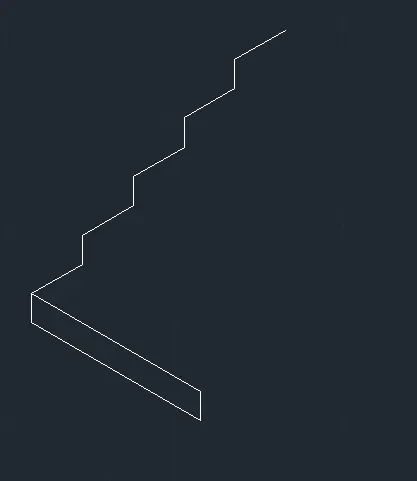
- Then using Isoplane left and PLINE the Treads and risers of the stairs are compleely drawn to scale.
- Then the PLINE is closed to form the complete drawing of the stairs.
C6:
Procedure:
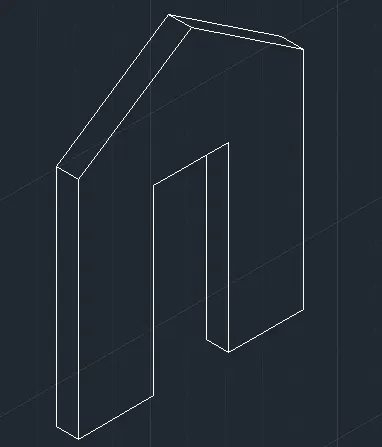
- First the ISODRAFT command is given to start isometric drafting.
- Ortho mode is switched on to maintain uniform angles.
- Then the outline of the Wall is first drawn using PLINE tool and Isoplane right.

- Then the 3D view is provided by using Isoplane left and PLINE command and giving the finish to the wall structure acoording to dimensions provided.
Report:
All the above drawings were done using various tools and commands that was taught in the week 2 session of the AutoCAD software.