Project 1_Comparative study of different storey buildings for Seismic forces
AIM:
-
To find factors influencing the dynamic characteristics of the buildings
-
To find factors influencing the Natural Period of a building.
-
To find factors influencing the Mode shape of oscillations
PROCEDURE:
BUILDING A:
STEP 1:
- Open the Etabs software.
- In the Start page select New model option.
- In the dialogue box that appears select the Use built in settings option.
- Change all the fields as required.
- Click on OK.
STEP 2:
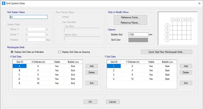
- In the dialogue box select Custom Grid spacing-> Edit Grid data.
- As per the specifications provide Grid data.
- Click on OK.
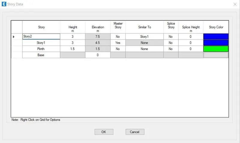
- In the dialogue box select Custom Story data-> Edit Story data.
- As per the specifications provide the height and elevations.
- Rename the stories as necessary.
- Set the Story 1 as master story.
- Set the other stories as Similiar to the Master story.
STEP 3:
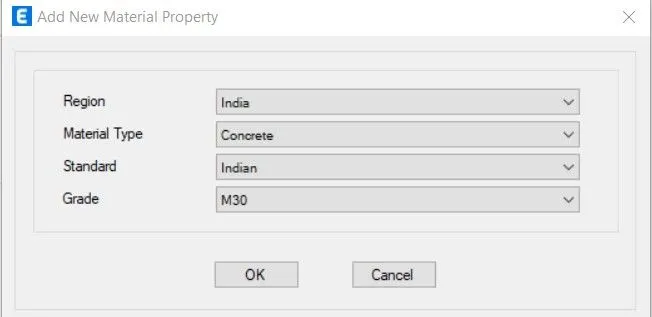
- To create the concrete material.
- Select Define-> Section Properties-> Frame sections.
- In the Define material dialogue box select Add new material option.
- Fill in the required fields as the following.
- Click on OK
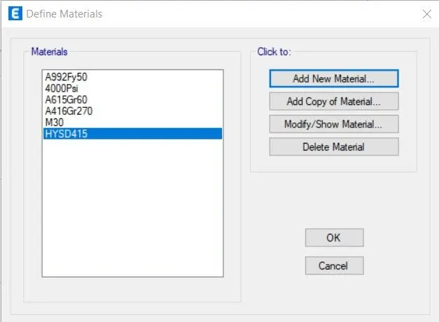
- Follow the same procedure to create rebar material.
- The required materials have been created
STEP 4:
BEAMS:
- To create the beams.
- Select Define-> Section Properties-> Frame sections.
- In the Define material dialogue box select Add new material option.
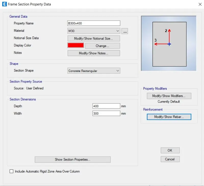
- Select Concrete rectangular option.
- Modify its properties as shown below.
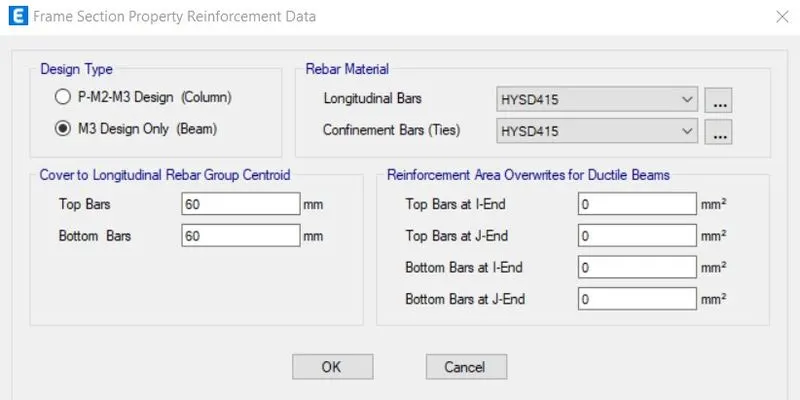
- Select the Modify/ Show rebar option.
- Modify its properties as shown below to create the beams.
COLUMNS:
- To create the columns.
- Select Define-> Section Properties-> Frame sections.
- In the Define material dialogue box select Add new material option.
- Select Concrete rectangular option.
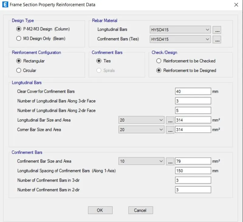
- Select the Modify/ Show rebar option.
- Modify its properties as shown below to create the columns
SLABS:
- To create the Slabs.
- Select Define-> Section Properties-> Slab sections.
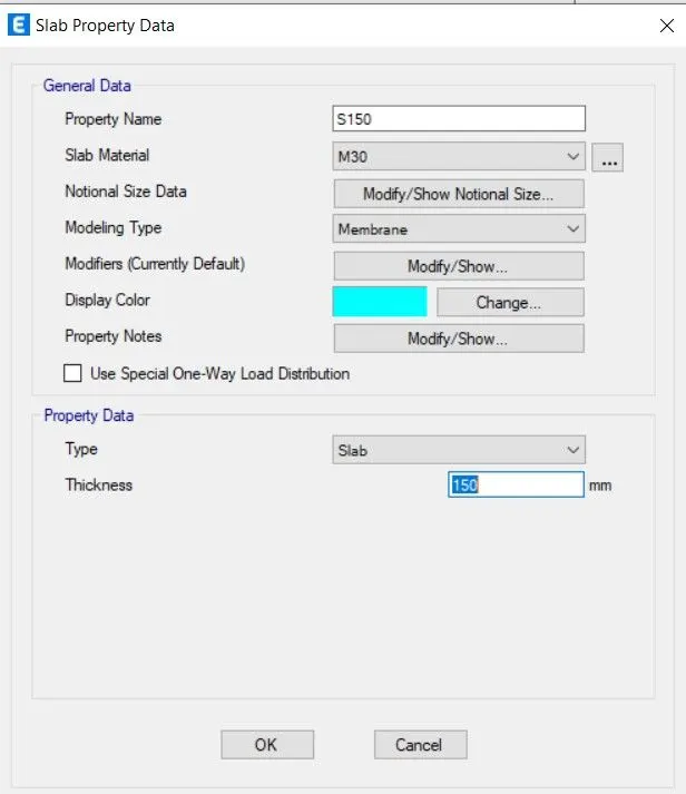
- In the dialogue box that appears select add new property.
- Rename or change the required fields as shown below.
- Click on OK
- The required Slab property has been created.
STEP 5:
- Select Define-> Load patterns.
- Add the following Load patterns.
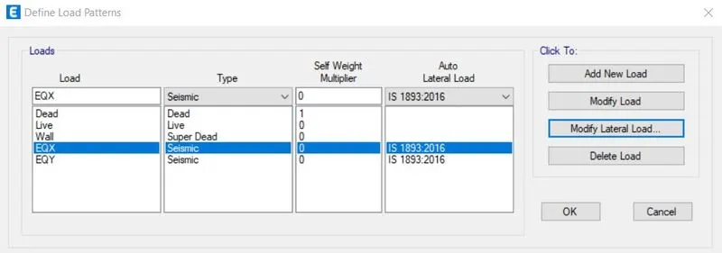
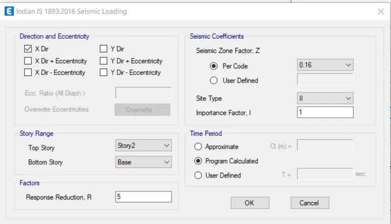
- For the loads EQX and EQY select Modify Lateral load.
- In Direction and Eccentricity panel check only X dir for EQX and uncheck the other boxes.
- Select only Y dir and uncheck other boxes for EQY.
- Click on OK.
STEP 6:
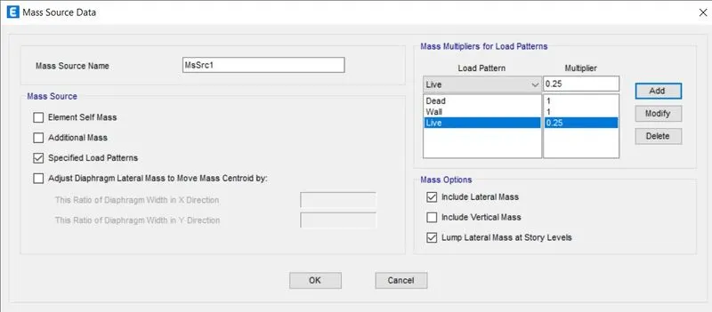
- Select Define-> Mass Source.
- In the dialogue box that appears select Modify Mass ource.
- In Mass source panel select specified load patterns and unselect others.
- Add the Load patterns and their multipliers as per Code as shown below.
- CLick on OK
STEP 7:
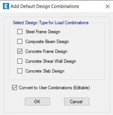
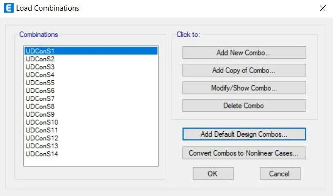
- To add load combinations select Define-> Load combinations-> Add default design combos.
- Check the Concrete Frame design box .
- Check the Convert to user combinaations box.
- Click on OK
- The Load combinations have been generated.
- Click on OK
STEP 8:
MODELLING:
Columns:
- Using Quick Draw columns icon columns will be drawn.
- In the Properties of object window change the Property of the column to the created one.
- Set the Working plane as All stories.
- Place the columns on the grids.
Beams:
- Using Quick Draw beams icon beams will be drawn.
- In the Properties of object window change the Property of the beams to the created one.
- Set the Working plane as All stories.
- By selecting the grid lines the beams are automatically placed.
Slabs:
- Using Quick Draw Floors icon slabs will be drawn.
- In the Properties of object window change the Property of the Slab to the created one.
- Set the Plan view to the Master story and set Working plane to similiar stories .
- By selecting the grids the slabs are automatically placed within its boundaries.
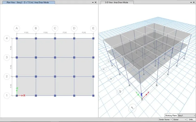
- Building A has been modelled succesfully.
STEP 9:
- To assign loads to the frames go to Select-> Properties-> Frame sections.
- Select the created Beams.
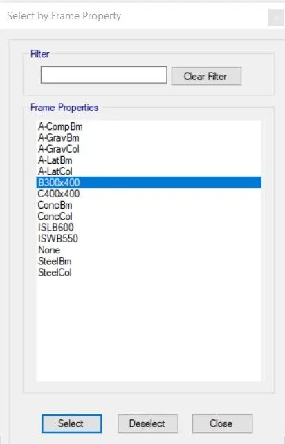
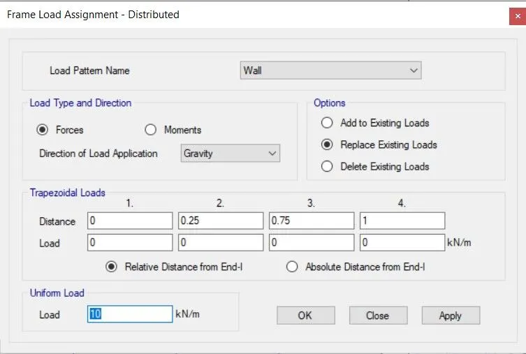
- Go to Assign-> Frame loads-> Distributed
- Change the required fields as shown below.
- Click on APPLY and OK.
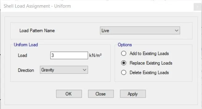
- To assign loads to the slabs go to Select-> Properties-> Slab sections.
- Select the created slabs.
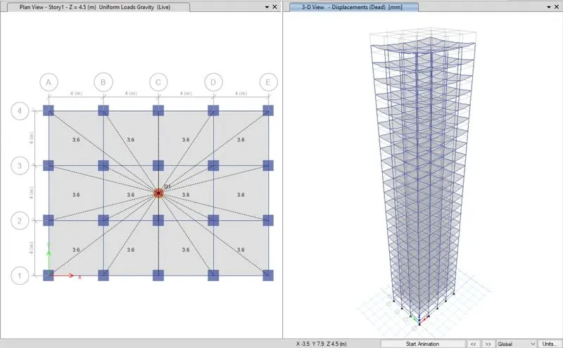
- Go to Assign-> Shell loads-> Uniform
- Change the required fields as shown below.
- Click on APPLY and OK
STEP 10:
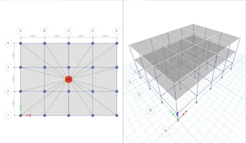
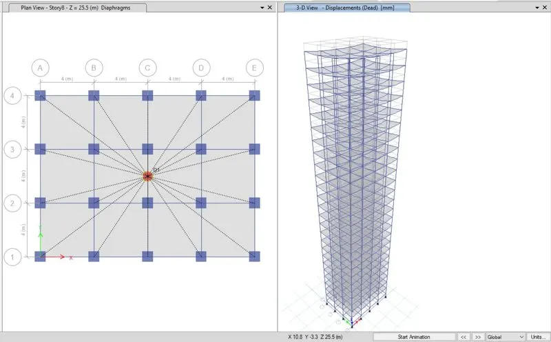
- To assign diaphragm selet Assign-> Shell-> Diaphragms-> D1.
- Click on APPLY and OK.
- The centre of mass is now automatically calculated.
STEP 11:
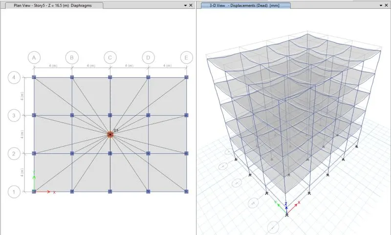
- Click on Run analysis icon.
- Once the analysis is complete click on Save icon to save the file.
BUILDING B:
STEP 1:
- Open Building A file in Etabs software.
- CLick on File-> Save As and save it as Building B.
STEP 2:
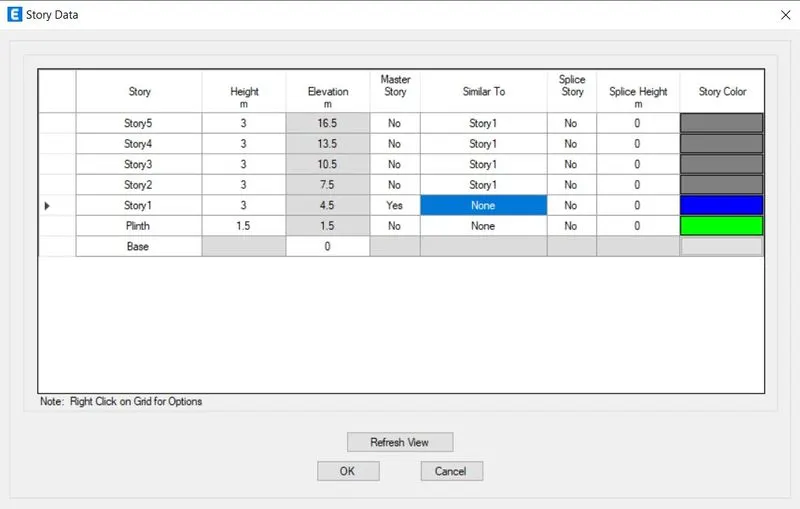
- Click on Edit-> Edit Stories and Grid systems.
- Edit the Story data as follows.
- Building B has the same Number of bays therefore grids are not changed.
STEP 3:
- Check if the loads have been applied.
- Click on Run analysis icon.
- Once the analysis is complete click on Save icon to save the file.
BUILDING C:
STEP 1:
- Open Building B file in Etabs software.
- CLick on File-> Save As and save it as Building C.
STEP 2:
- Building C has the same Number of stories and bays therefore they are not changed.
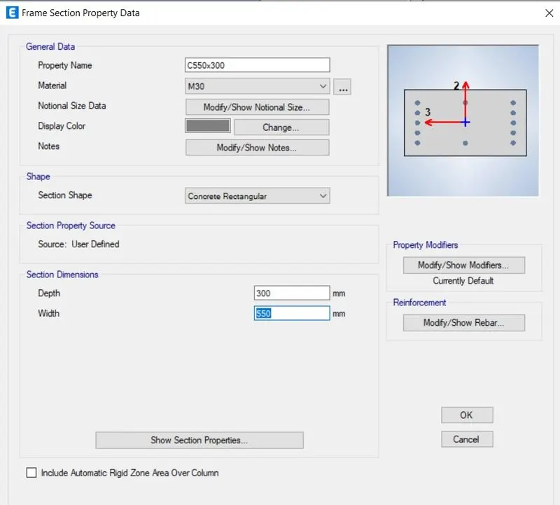
- To change the column size go to Define-> Section properties-> Frame sections.
- Select the previoulsy created column property and select Modify property option.
- Modify its properties as shown below to create the required columns.
STEP 3:
- Click on Select-> Select-> Properties-> Frame sections.
- Choose the created columns.
- Click on Assign-> Frame-> Local axes.
- Edit the angle to 90 degrees.
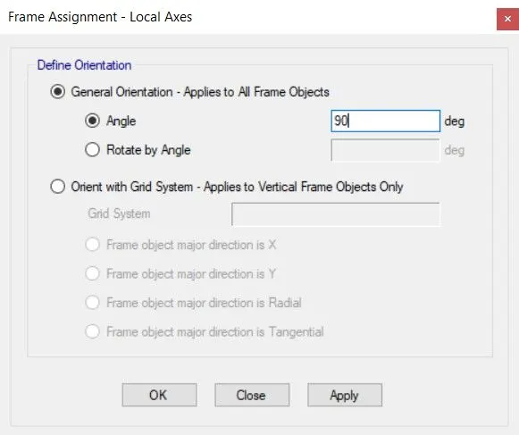
- The column has been oriented as specified.
STEP 4:
- Check if the loads have been applied.
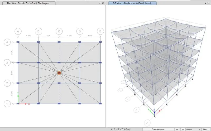
- Click on Run analysis icon.
- Once the analysis is complete click on Save icon to save the file.
BUILDING D:
STEP 1:
- Open Building C file in Etabs software.
- Click on File-> Save As and save it as Building D.
STEP 2:
- Building D has the same Number of stories and bays therefore they are not changed.
- The only required change is the orientation of columns.
- Click on Select-> Select-> Properties-> Frame sections.
- Choose the created columns.
- Click on Assign-> Frame-> Local axes.
- Edit the angle to 0 degrees.
STEP 3:
- Check if the loads have been applied.
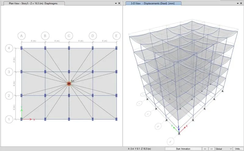
- Click on Run analysis icon.
- Once the analysis is complete click on Save icon to save the file.
BUILDING E:
STEP 1:
- Open Building D file in Etabs software.
- Click on File-> Save As and save it as Building E.
STEP 2:
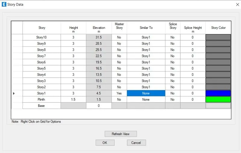
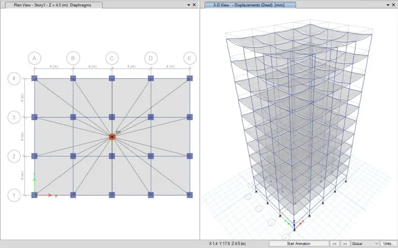
- Click on Edit-> Edit Stories and Grid systems.
- Edit the Story data as follows.
- Building E has the same Number of bays therefore grids are not changed.
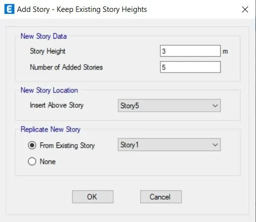
- In the dialogue box select Custom Story data-> Edit Story data.
- As per the specifications provide the height and elevations.
- Rename the stories as necessary.
- Set the Story 1 as master story.
- Set the other stories as Similiar to the Master story.
STEP 3:
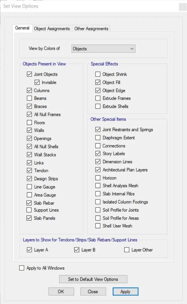
- Click on View-> Set Building view limit.
- Set the view to Top 5 stories.
- Click on Set display options icon and uncheck Beams and Floors.
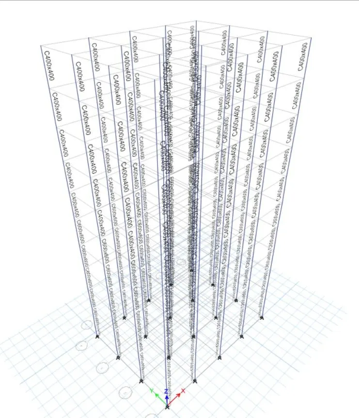
- Select all the columns and click on Assign-> Frames-> Section properties and select the specified column size.
STEP 4:
- Click on View-> Set Building view limit.
- Set the view to Bottom 5 stories.
- Click on Set display options icon and uncheck Beams and Floors.
- Select all the columns and click on Assign-> Frames-> Section properties and select the specified column size.
STEP 5:
- Check if the loads have been applied.
- Click on Run analysis icon.
- Once the analysis is complete click on Save icon to save the file.
BUILDING F:
STEP 1:
- Open Building E file in Etabs software.
- Click on File-> Save As and save it as Building F.
STEP 2:
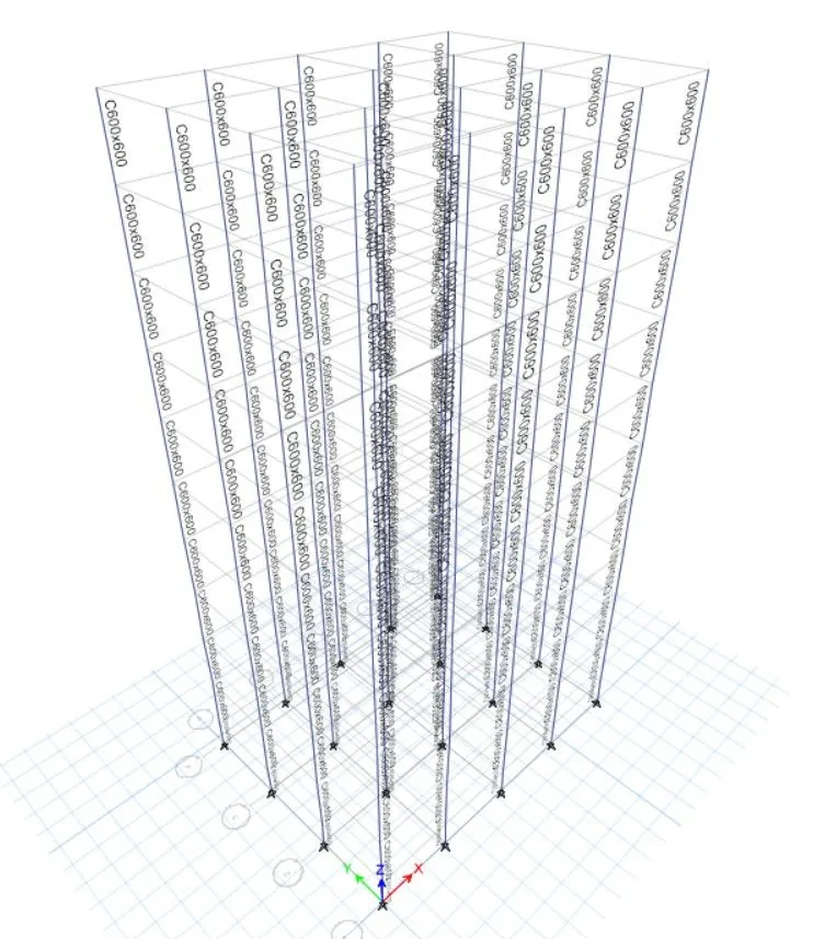
- Click on View-> Set Building view limit.
- Set the view to Top 5 stories as only they require to be changed.
- Click on Set display options icon and uncheck Beams and Floors.
- Select all the columns and click on Assign-> Frames-> Section properties and select the specified column size.
STEP 3:
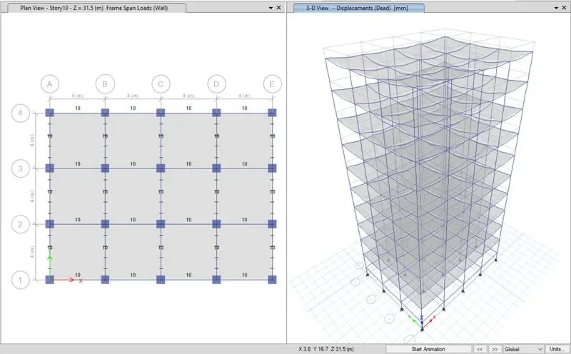
- Check if the loads have been applied.
- Click on Run analysis icon.
- Once the analysis is complete click on Save icon to save the file.
BUILDING G:
STEP 1:
- Open Building F file in Etabs software.
- Click on File-> Save As and save it as Building G.
STEP 2:
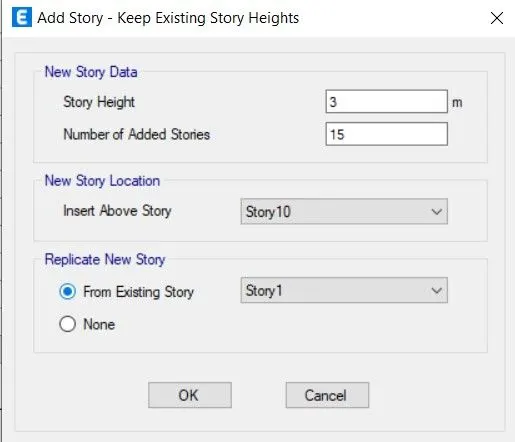
- Click on Edit-> Edit Stories and Grid systems.
- Edit the Story data as follows.
- Building E has the same Number of bays therefore grids are not changed.
STEP 3:
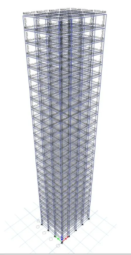
- To assign the different column properties the same method as used for Building E is followed.
STEP 3:
- Check if the loads have been applied.
- Click on Run analysis icon.
- Once the analysis is complete click on Save icon to save the file.
BUILDING H:
STEP 1:
- Open Building G file in Etabs software.
- Click on File-> Save As and save it as Building H.
STEP 2:
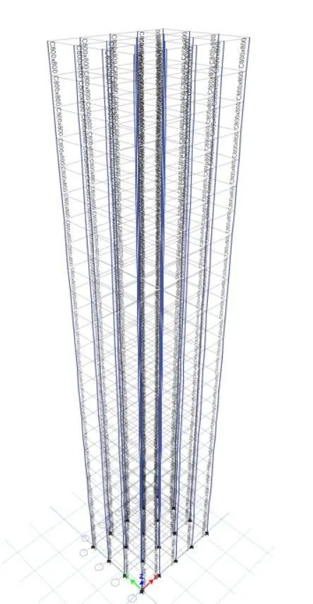
- Using the same procedure to assign the specified column properties to the specified floors.
STEP 3:
- Check if the loads have been applied.
- Click on Run analysis icon.
- Once the analysis is complete click on Save icon to save the file.
BUILDING J:
STEP 1:
- Open Building H file in Etabs software.
- Click on File-> Save As and save it as Building J.
STEP 2:
- Click on Select-> Select-> Properties-> Slab sections.
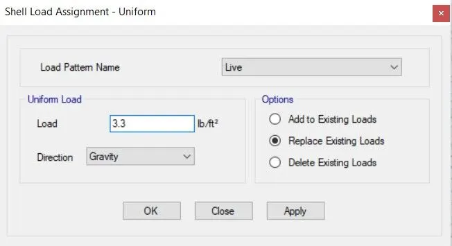
- Click on Assign-> Shell loads-> Uniform.
- Edit the load and add 10%.
STEP 3:
- Check if the loads have been applied.
- Click on Run analysis icon.
- Once the analysis is complete click on Save icon to save the file.
BUILDING K:
STEP 1:
- Open Building J file in Etabs software.
- Click on File-> Save As and save it as Building K.
STEP 2:
- Click on Select-> Select-> Properties-> Slab sections.
- Click on Assign-> Shell loads-> Uniform.
- Edit the load and add 20%.
STEP 3:
- Check if the loads have been applied.
- Click on Run analysis icon.
- Once the analysis is complete click on Save icon to save the file.
ANALYSIS and RESULTS:
1) Effect of stiffness on T:
Building E :- 1.73s
Building F :- 1.73s
Building G :- 4.17s
Building H :- 4.41s
Conclusion :-
- For the 10 storey buildings with varying column sizes (Building E) and uniform column sizes (Building F) there is no significant difference in the Effect of stiffness on Time period between both buildings.
- The 25 storey building with varying column sizes (Building G) is more stable than the uniform column sizes (Building H) due to the comparartively higher mass on the upper floors which induces more lateral displacement of the building causing greater time period.
2) Effect of Mass on T:
Building H :- 4.41s
Building J :- 4.42s
Building K :- 4.43s
Conclusion :-
- Since the distribution of mass is even throughout all the floors the difference in Effect of Mass on Time period among the buildings is not significant.
3)Effect of Building Height on T:
Building A :- 0.5s
Building B :- 1.036s
Building F :- 1.73s
Building H :- 4.41s
Conclusion :-
- It is seen than Time period increases with respect to height of the buildings.
4) Effect of Column orientation on T:
Building B :- 1.03s
Building C :- 1.145s
Building D :- 1.12s
Conclusion :-
- Due to the same size of column in both x and y directions there is no Significant effect on the Time period caused by the Column orentation in Building B.
- Column size is larger in the X direction for Building C and smaller in the X direction for Building D. Therefore when the column size in X direction is less the displacement is higher consequently when the column size is higher in X direction the displacement is lower.
5) Effect of Flexural stiffness on T:
Building B:
Flexural stiffness (Regular) :- 1.03s
Flexural stiffness (Zero inertia) :- 2.627s
Conclusion :-
- When the Stiffness of the beam is not considered Time period is almost doubled.
6) Effect of Axial stiffness of vertical members on mode shape:
Building H:
Full axial cross sections for columns (Regular) :- 4.41s
Axial cross sections for columns is close to nil (Zero inertia) :- 5.99s
Conclusion :-
- Axial stiffness plays an important role in the Time period of the building.
7) Effect of Flexural stiffness of Structural elements on mode shape:
Building B:
Column support pinned (Regular) :- 1.03s
Column support fixed :- 0.94s
Conclusion :-
- Fixed support leads to lesser time period.