Project 1 Mechanical design of battery pack
Aim: To design a battery pack with an enclosure of a capacity of 18 kWh using ANR26650M1-B cell
Theory:
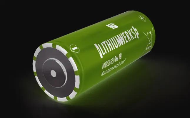
This cell is based on Lithium Iron Phosphate chemistry. The cell is capable of delivering high power with the use of patented Nanophosphate technology. This enables the cell to work optimally in wide temperature ranges, for a higher lifecycle, be safer with multiple safety layers, charge faster with higher C rates and perform consistently.
- The cell has Lithium Iron Phosphate LiFePO4 as cathode material and graphite carbon electrode as anode
- This cell chemistry has lower energy density and lowers operating voltage than Lithium Cobalt Oxide cell.
- This type of cell has long term stability and is of low cost
- It has a higher peak power rating and higher current compared to other lithium-ion cells.
- Lithium Iron Phosphate cell has slower rate of capacity loss, hence it has the highest shelf life compared to any other type of Lithium-ion cell. Though LFP cell has lower energy density, it would have the same capacity as that of LCO cell after one year of shelf life.
- LFP cell is intrinsically safer than other lithium-ion cells. Cobalt has negative temperature coefficient of resistance that encourages thermal runaway. The Phosphor-oxygen bond in phosphate ion is more stable than the cobalt-oxygen bond in cobalt oxide ion, hence the oxygen is released more slowly in LFP cells in a thermal runaway situation, which makes it safer.
- LFP cell does not decompose at high temperatures
- Lithium is not present in cathode of fully charged LFP cell while 50 % of lithium is present in LCO cell. Hence LFP cell is more efficient.
Dimension of the cell:
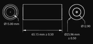
As the name of the cell suggests, the cell diameter is approximately 26 mm and the cell length is close to 65 mm. The cell is of cylindrical form factor.
Specifications of the cell:
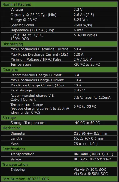
- The peak C-rate of the cell = peak cell current / cell capacity = 120 / 2.5 = 48 C
- The continuous C-rate of the cell = Max continuous discharge current / cell capacity = 50 / 2.5 = 20 C
Discharge Voltage characteristics of the cell:
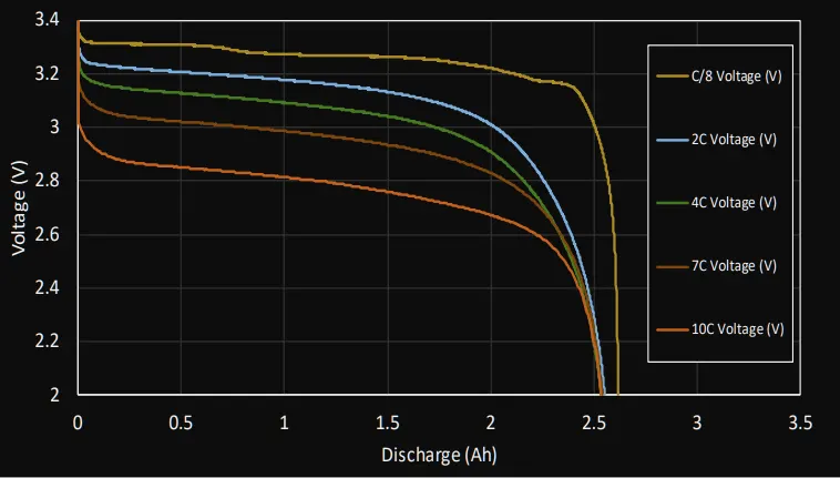
- The plot shows the cell voltage at different discharge rates against the cell capacity at ambient temperature of 23 degrees celsius.
- The maximum voltage of the cell is close to 3.3 V
- The nominal voltage of the cell is close to 3 V and the usable or nominal capacity of the battery is 2 Ah
- The cut-off voltage of the cell is 2 V and the maximum capacity of the cell is 2.6 Ah.
Ageing of the cell:
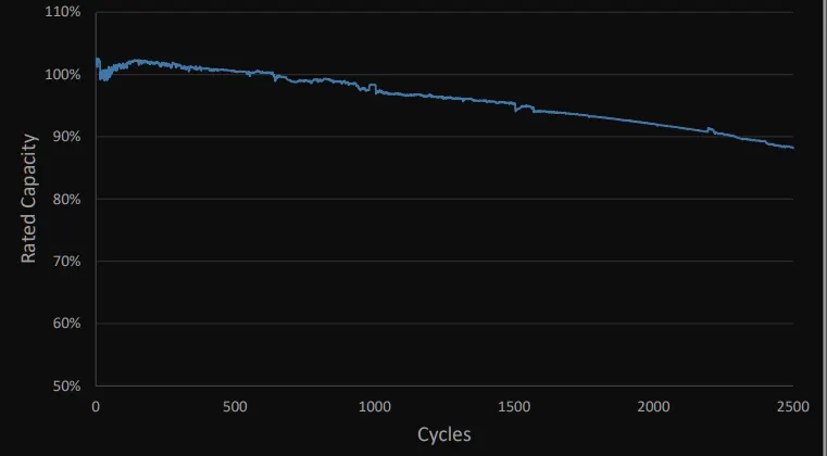
- The plot shows the ageing of the cell: the reduction of the cell capacity with charge/discharge cycles conducted at room temperature at 1 C rate.
- When the cell is unused, the rated capacity of the cell is 100 % which is equivalent to 2.6 Ah.
- With the usage of cell, considering full discharge and charge cycles, the cell capacity reduces.
- At the end of 2500 cycles, the cell capacity is reduced by 12 % or to 2.38 Ah.
- The cell is capable of lasting for 4000 cycles.
Battery Pack Architechture:
A cell is the smallest division of the battery pack and also the smallest division of the voltage. The cells are connected in series and or parallel to form modules and these modules are connected again in series and or parallelly to form battery pack.
Determination of number of cells in series:
The voltage of the battery pack is determined by the number of cells connected in series

In the above example, each cell has terminal voltage of 2 V and 6 number of cells are in series connections. Thus the total voltage of this string is 6*2=12V
Assumption: The current battery pack application is considered to be an EV requiring voltage as high as 400 V.
The number of series ANR26650M1-B cells required to fulfill the voltage demand (Ns)= Voltage required/individual cell voltage = 400/3.3 = 121.21. Rounding off this number to higher integer = 122 cells
Determination of the number of cells in parallel:
The capacity of the battery pack is determined by the number of cells connected in parallel
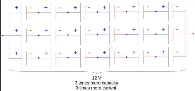
In the above example, 3 cells are connected in parallel, hence the battery pack capacity is equal to 3 times that of individual capacity.
Given: Battery energy capacity=18 kWh
Required Battery charge capacity = Energy capacity / battery voltage = 18000 Wh/ 400 V = 45 Ah
Number of cells connected parallelly (Np) = Required Battery capacity / individual cell capacity = 45 Ah/ 2.5 Ah = 18 cells
Hence the total number of cells in the battery pack = Ns * Np = 122 * 18 = 2196 cells.
Battery Pack Calculations:
- Volume of each cell = `pi/4 * D^2*L`where D is diameter and L is length of cell
- `V=pi*0.026^2*0.065/4 = 0.0000345104`or V= 0.0345 litre
- Volumetric energy density of the cell = Cell energy/cell volume = 8.25 Wh / 0.0345 l = 239 Wh/l
- Gravimetric energy density of cell = Cell energy/cell mass = 8.25 Wh / 0.076 kg = 108.55 Wh/kg
- Battery pack mass = Total number of cells * individual cell mass = 2196 * 0.076 kg = 166.89 = 167 kg (considering only the cell mass)
- Volume of the battery pack = Total number of cells * Cell volume = 2196 * 0.0345 = 75.78 litre
- Battery pack peak current = cell peak current * Np = 120 * 18 = 2160 A
- Battery pack peak power = Battery pack peak current * battery pack voltage = 2160 * 400 = 864 kW
- Battery pack continuous current = cell continuous current * Np = 50 * 18 = 900 A
- Battery pack continuous power = Battery pack continuous current * battery pack voltage = 900 * 400 = 360 kW
Battery pack design:
Guidelines:
- The battery pack should allow heat transfer so that the battery temperature is maintained within 50 degrees celsius for safety
- The battery pack should suppress the vibration frequencies to avoid resonance at the natural frequencies of other vehicle systems
- The battery pack should be designed in such a way that it considers and addresses issues like thermal runaway, vibration isolation and crash safety.
- It is important to restrict the movement of cell or module undergoing thermal runaway so that it does not come into direct contact with an adjacent cell or module. This would transfer the heat more effectively to the entire battery pack due to conduction.
- In the event of thermal runaway, the cells generate hot gasses. These hot gasses cannot remain in the battery pack, as they could impact the whole battery pack. Hence special gas exhaust nozzles are integrated with battery pack, that provide an outlet for the affluent gasses away from the passengers. These nozzles are normally closed by pressure equalizing value and open when the pressure builds up.
Material selection of the battery pack:
- The side member and the base plate of the battery pack is made of lightweight material like Aluminum. This supports weight of the battery pack and also sustains thermal and mechanical shocks.
- The battery pack cover is made of a material that is electrically insulating and thermally conducting so that it allows the heat dissipation of the battery pack
- The cell spacers are made of materials that are thermally and electrically insulating and rigid like PTFE.
Creating a thermal barrier:
At module level:
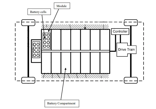
The battery pack is not made as a big matrix rather it is modularized. The battery pack is divided into several modules and each module is held in a single battery compartment created by cross members. Each module consists of the same number of cells. The battery pack member running in the centre creates distance between the right and left modules and allows space for power and data busses. The cross members hold the modules rigidly in place at distance from each other and create an air gap between the modules and battery cover plates. This ensures that the module heat is not transmitted to other modules through cover plate conduction.
At cell level:
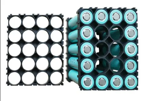
Cell spacers are shown in this image. Cell spacer is required to separate two adjacent cells by a minimum distance of 2 mm. This is required to ensure that heat of a cell is not transmitted to adjacent cells. Cells spacers are rigid and are present at the upper and lower parts of cells. This configuration is preferred over cell spacer running along the length of cell for weight reduction purposes. The spacer is seen to be bonded or well integrated into the cell mounting bracket.
Vibration isolation:
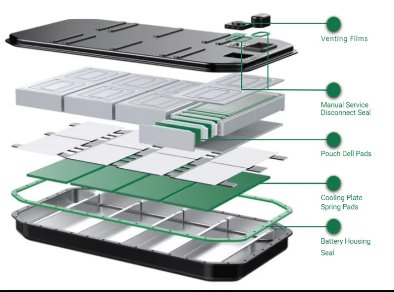
The engine and the suspension system of the vehicle generate vibrations that can be transmitted to the battery pack. These vibrations can develop dynamic load and affect the electrical continuity in the bus bars and terminal connectors and also cause fatigue failure of the battery pack structure. When the vehicle moves on the uneven road surface, vertical and lateral forces are generated and when vehicle accelerates and decelerates, longitudinal forces are generated that impact the battery pack. In order to protect the battery pack from these forces, damping pads are required. The damping pads are placed between the battery pack and base plate to attenuate the vertical forces on the battery and damping pads are also placed between the modules to attenuate the lateral and longitudinal forces.
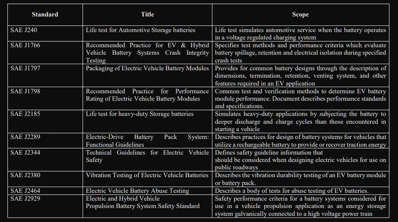
The following table provides the standard tests for battery pack design:
Modularizing of the battery pack:
A battery pack cannot be a large matrix of cells connected in series and parallel. It needs to be divided into smaller sections called modules. A module consists of few cells having a configuration. The requirement of modularization of the battery pack:
- If a cell fails (Thermal runaway or explosion), then only the particular module that contained the weak cell needs replacement. The module has its own enclosure that contains the damage within itself and protects the rest of the battery pack. This way, the battery pack does not need a replacement.
- The battery modules provide a better heat dissipation prospectus than a single large battery pack
- The modules make the battery pack serviceable
Process of modularizing battery pack:
- The battery pack requires 2196 numbers of 26650 LFP cells: 122 in series and 18 in parallel connection. In order to make smaller modules, this pack of 122 * 18 cells needs to be divided into sections.
- Since a small number of cells are present in parallel connections, it is not divided. Hence module contains 18 parallel cells.
- Since a large number of cells are in series connections, it requires division. 122 number has two feasible factors: 2 and 61. Since parallelly connected cells have no division, the number of battery modules depends on series division. Hence the battery pack can be modularized into 2 modules or 61 modules. Since 2 modules make battery pack large and unmanageable, it is divided into 61 modules.
- It is obvious that of 61 modules, each module consists of 18 cells in parallel and 2 cells in series since 122 series cells divided into 61 parts gives us cells in series. This gives us the module configuration of 2S18P as shows in the image below:
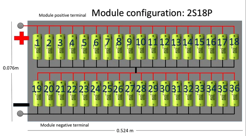
- In this module, cells are placed upright adjacent to each other using a cell spacer of 2 mm. The module contains 2 parallel lines of 18 cells connected in series.
- The module capacity is the same as the pack capacity of 45 Ah.
- The module voltage = 3.3 V * 2 (series cells in module) = 6.6 V
- The length of module = (diameter of a cell+cell spacer width) * number of cells in a parallel line + module enclosure thickness = (0.026 m + 0.002 m) * 18 cells + 0.02 m = 0.524 m
- The width of module = (diameter of a cell+cell spacer width) * number of cells in series + module enclosure thickness = (0.026 m + 0.002 m) * 2 cells + 0.02 m = 0.076 m
- Heigth of the module = Length of the cell+ allowance + module enclosure thickness (base and top cover) = 0.065 m + 0.005 + 0.02 = 0.09 m
- Total volume of the module = length * width * height = 0.524 * 0.076 * 0.09 = 0.003584 m^3 = 3.584 Litre
- The battery module terminal connections are provided out of the battery pack
- The module casing is made of metal
- The electrical connections between the cells are of copper strips.
The battery modules are connected to make a battery pack as shown below:
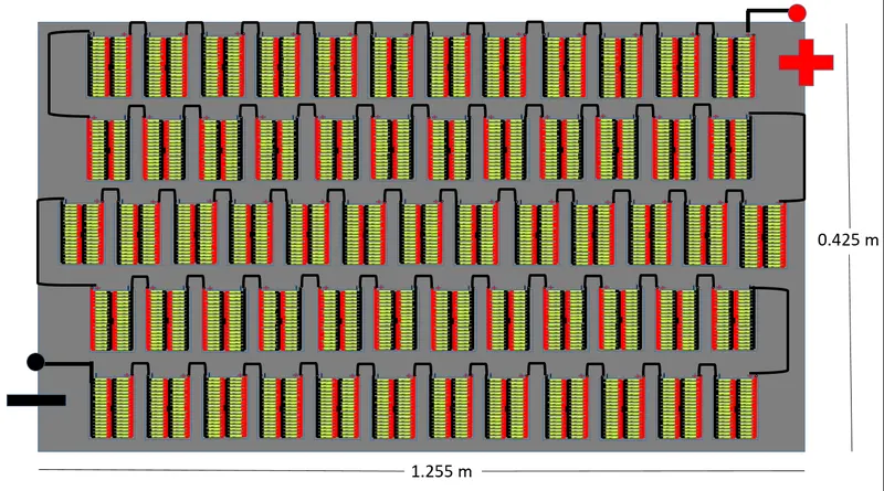
- A battery module satisfies the battery capacity requirements, hence the battery modules are only required to fulfil battery voltage requirements. This can be done by connected all the modules in series as shown in the image.
- 61 battery modules are connected in series; Hence the ultimate battery pack voltage = battery module voltage * number of modules in series = 6.6 * 61 = 402.6 V
- In order to make module series connections, the negative terminal of a module is connected with the positive terminal of an adjacent module.
- In the battery pack, the modules are arranged in such a way that cell length becomes parallel to the base plate. In a battery module, cell parallel line is parallel to base plate and in battery pack, cell parallel line of module is perpendicular to the pack base plate. The modules are vertically placed as shown in the image adjacent to each other on the pack-base plate. Hence the module terminal connections are available on the top side. The modules are arranged in 5 lines. Each line consisting of 12 modules except the middle line with 13 modules.
- Length of battery pack = (Height of the module + module spacing) * max number of modules in row+ battery pack enclosure thickness = (0.09 m+ 0.005 m) * 13 + 0.02 m = 1.255 m
- Width of battery pack = (width of the module + module spacing) * number of module rows + battery pack enclosure thickness = (0.076 m + 0.005 m) * 5 +0.02 m = 0.425 m
- Height of battery pack = Length of battery pack + allowance + battery pack enclosure thickness = 0.524 m+0.05 m+ 0.02 m = 0.6 m
- Total volume of battery pack = (length * width * height = 1.255 * 0.425 * 0.6 = 0.320 m^3 = 320 Litre
Reference:
- EV design – battery calculation – x-engineer.org
- https://a123batteries.com/anr26650m1-b-lithiumwerks-nanophosphate-3-3v-2-5ah-lithium-iron-phosphate-battery/
- https://en.wikipedia.org/wiki/Lithium_iron_phosphate_battery
- https://www.researchgate.net/publication/323084845_Mechanical_Design_and_Packaging_of_Battery_Packs_for_Electric_Vehicles