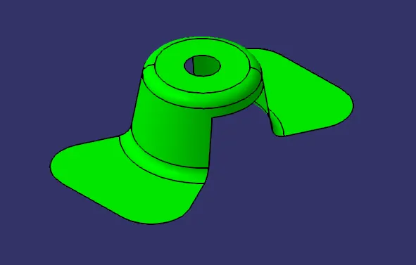
Week 8 - Challenge 1 - Draft Analysis on a Fan Cover
Draft analysis:
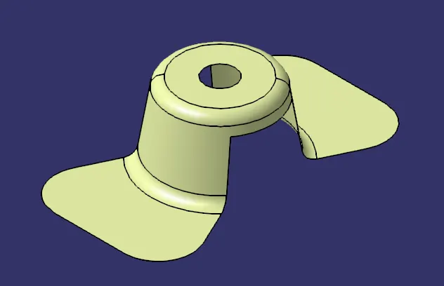
The above image shows the plastic component: Fan cover. The component is designed using surface modelling techniques. Before the thickness is alloted to the surface to form solid part, draft analysis needs to be performed.
1. Initially, it is made sure that the surface model of the fan cover does not have any free edges where two surfaces are joined. To ensure all the surfaces are stitched together, Join command or boundary command is used in Generative Shape Design workbench.
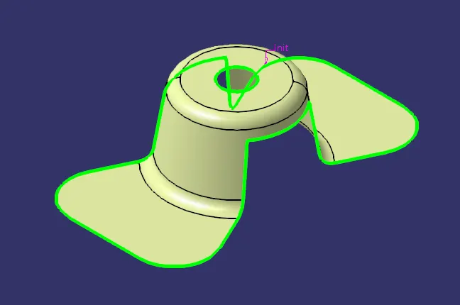
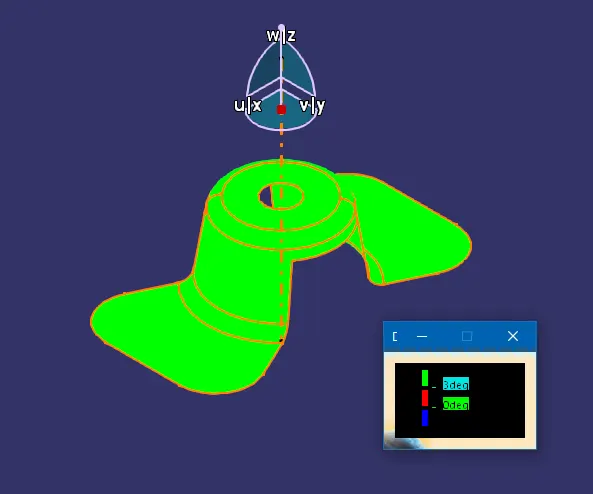
All the free edges are highlighted in green colour. So it confirms that all the surfaces are joined properly.
2. Checking possible tooling direction: The feasible tooling direction is manually checked by rotating the component.
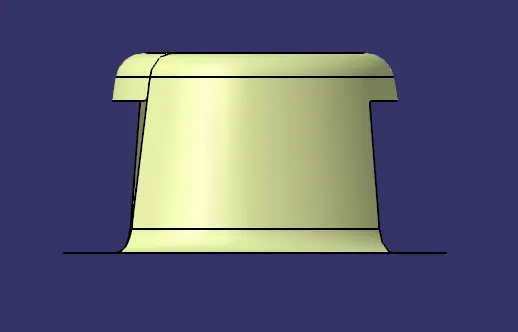
- The component is oriented to X direction. However the part cannot be split and made to move in x-direction in the mould due to the hole at the top and slots in the side. The hole in the top required side core to manufacture this undercut and it significatly increased the manufacturing cost. So this direction is eliminated.
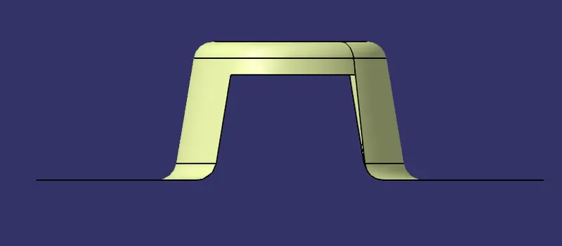
- The part is oriented in Y direction. This tooling direction is also not feasible due to the hole undercut at the top.
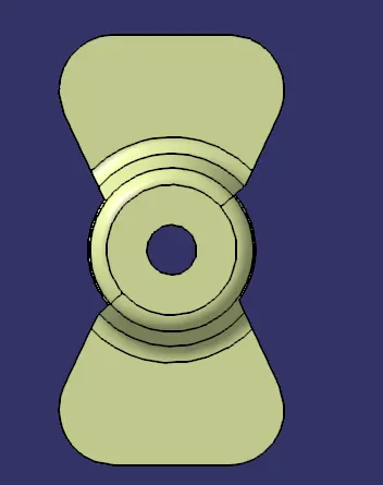
- The tooling direction Z is considered here. Since the core can be moved and the component can be ejected in Z-direction without requirement of the extra manufacturing equipment like side core, a dummy tooling direction is created along Z axis.
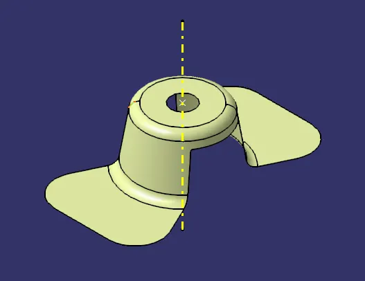
Dummy tooling axis is created by creating a point using the top hole as circle reference and creating a line using point-direction method.
3. Creation of tooling axis:
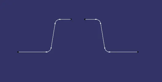
- The component is intersected with ZX plane to obtain the component outline when viewed orthogonally from Y direction.
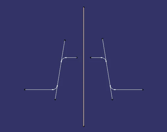
- Lines are created to extend the slant outline of the component using point-point method.
- Tooling axis is generated for Y direction that conforms to the geometry of the component in ZX plane. Bisect method is used to generate the tooling axis by selecting both the slant boundary lines.
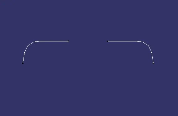
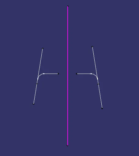
- A similar procedure is followed for the ZY plane of the component and to generate tooling axis that conforms with the X direction of the component.
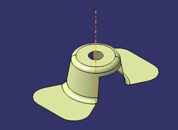
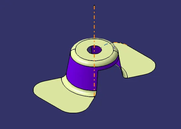
- The final tooling axis is obtained by bisecting both X and Y direction tooling axes. This tooling axis is highlighted below.
4. Performing the draft analysis:
The component creates a problem when the draft angle of the faces of the component that are not perpendicular to the tooling axis are either parallel (make 0 to 3 degree angle with tooling axis) or make negative angle (inclined towards the core side of the mould. This issue makes it difficult to eject the component from the core. Hence draft analysis is performed to make sure that top faces of the component make angle greator than 3 degree with tooling axis.
The face that can possible create an issue is highlighted with purple colour.
The Feature Draft Analysis option is selected and compass is aligned on the tooling axis. When the component is selected, the top faces turn green. This shows that all the top faces are having draft angle of greater than 3 degrees.
The purple face which was thought to cause draft issue makes an angle of 9.196 degrees and is ensured to have safe deaft angle.
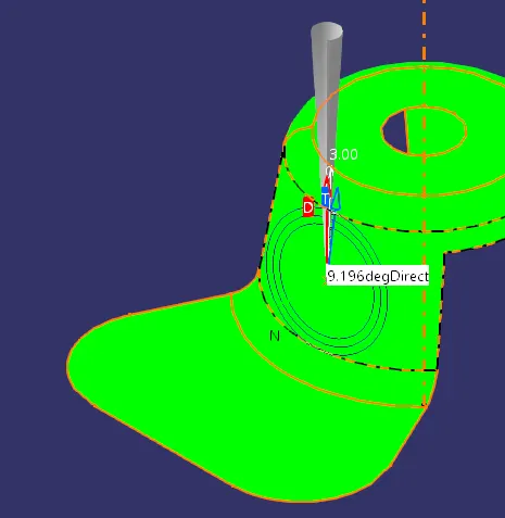
Hence the draft analysis concludes that the part is safe to be manufactured along Z- tooling direction.