Project-1: Powertrain for aircraft in runways
Problem Statement:
Part A:
1. Search and list out the total weight of various types of aircrafts.
2. Is there any difference between ground speed and air speed?
3. Why is it not recommended to use aircraft engine power to move it on the ground at Airport?
4. How an aircraft is pushed to runway when its ready to take off?
5. Learn about take off power, tyre design, rolling resistance, tyre pressure, brake forces when landing.
Part B:
6. A. With necessary assumptions, calculate the force and power required to push / pull an aircraft by a towing vehicle.
B. Develop the model for the calculated force and power using Simulink.
7. A. Design an electric powertrain with type of motor, it’s power rating, and energy requirement to fulfill aircraft towing application in Simulink. Estimate the duty cycle range to control the aircraft speed from zero to highest. Make all required assumptions. Prepare a table of assumed parameters. Draw a block diagram of powertrain.
(Hint :DC7 Block)
B. Also, Design the parameters in excel sheet.
Solution:
Part A:
1. Various types of aircraft:
| Aircraft type | Total weight (kg) | |
| 1 | Helicopter | 1500 |
| 2 | Turboprop aircraft | 3670 |
| 3 | Piston Aircraft | 1157 |
| 4 | Light jet | 4540 |
| 5 | Midsize jet | 13500 |
| 6 | Jumbo jet | 350000 |
| 7 | Regional Jet | 39000 |
| 8 | Narrow-body aircraft | 124000 |
| 9 | Widebody airlines | 650000 |
| 10 | Commuter liner | 18000 |
| 11 | Airbus | 575000 |
| 12 | Concorde | 78700 |
| 13 | Tupolev Tu-144 | 85000 |
| 14 | Military aircraft | 381000 |
| 15 | Fighter | 20000 |
| 16 | Water bomber | 20000 |
| 17 | Maritime Patrol | 23000 |
| 18 | Multirole combat | 13000 |
| 19 | Transport | 6000 |
2. Difference between ground speed and air speed of an aircraft:
| Airspeed | Groundspeed |
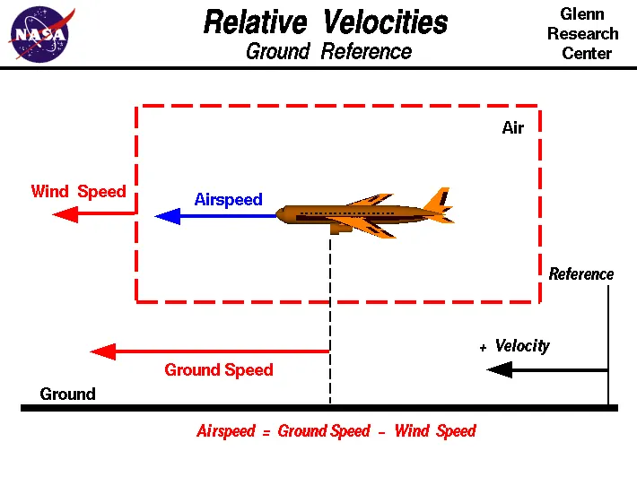
| It is the speed of the aircraft relative to the airflow around the aircraft | It is the speed of an aircraft relative to the surface of earth. |
| Airspeed is also the speed with which air is flowing around the aircraft body. It affects the aircraft speed in all directions | Ground speed is the horizontal speed of an aircraft and it is zero if the aircraft moves vertically. |
| Airspeed determines if there is enough flow of air around aircraft body to to provide the lift force | Ground speed determines the time taken to reach the destination |
| Airspeed is the difference between the aircraft speed and wind speed | Groundspeed is the sum of aircraft speed and wind speed.It |
| During tailwind, airspeed is comparatively lower | During tailwind, Ground speed is aided by wind speed and it is comparatively higher |
| During headwind, airspeed is higher | Headwind offers resistance to aircraft and slows down the groundspeed. |
3. Reasons for not using airplane engine to move on the ground:
- Ground has more obstruction due to which the airplane requires precise maneuring. The pilot in the cockpit does not have good view of the ground obstructions. Hence towing truck is assists the plane to maneure properly.
- Airplane engine has very low eficiency at low power setting required for taxiing or moving on the ground. Taxiing is the movement of plane to reach runway or hangar and this operation requires hundreads of liters of fuel. In order to save fuel, engine power is not required.
- Engine can be used in powerback mode, wherein engine runs to provide reverse thrust. But the airplane is required to move backwards at the terminal gate. So the reverse thrust can damage the terminal building or push the debris and dirt in front of the engine which could get sucked into engine when it powers forward damaging the engine.
- Airplane engines make harsh noise which disturbs the surrounding. The thrust obtained at the rear end of the engine is so powerful that could cause serious damage to the objects on the backside of the plane. There is high chance of accident due to the thrust on ground. For the safety concerns, airplane is towed.
4. How an aircraft is pushed to runway:
- The process of moving the airplane to runway when it is ready to take-off is called as Taxiing.
- During Taxiing the plane runs on its own power on its wheels. The wheels on the front-side of plane are called nose wheels and the wheels on rear-side are called tail wheels. The steering maneuer is achieved by turning either the nose wheels or tail wheels. The thrust to move forward is gained by propellers or jet engines.
- During taxiing, plane moves slow on taxiway at speed of 30-35 km/h
5. Aircraft design:
- Power required for take-off:
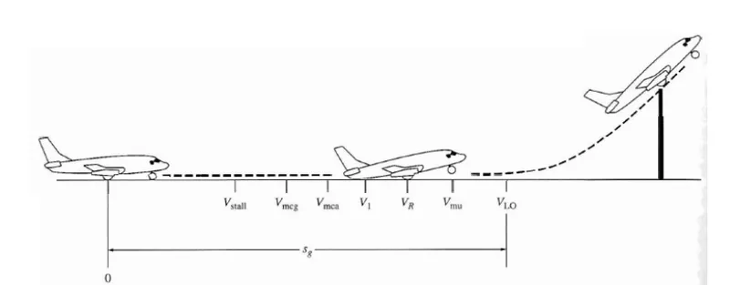
- The above image shows the take-off maneuer of a flight. The take-off distance is divided into two parts. Part 1 is called and ground roll and immediately after ground-roll the plane lifts off from the ground completely. The part 2 is the distance taken by the plane to reach a clearance height of 35 ft.
- Part 1: At the extreme left the plane is at rest. The pilot releases the brakes and pushes the thrust lever. The engine provide the thrust and airplane starts moving and attains velocity Vstall. Vmcg is the velocity at which the vertical fin and rudders come into effect because of availability of enough aerodynamic drag. If there is an engine failure, the yaw motion generated as an effect can be counteracted by manipulating vertical fin at Vmcg: Minimum control speed on ground. Vmca is minimum control speed in air, at this speed yaw motion can be effectively counteracted if the plane is in air. V1 is called the decision speed at which pilot handles the flight control to be prepared for take-off. At this speed, plane can take-off despite of engine failure. Vr is the rotational speed at which the pilot maneuers the wing flaps using flight control to produce pitch motion to lift off the nose and increase the angle of attack. Vlo is the lift off speed when the plane is completely off the ground.
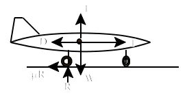
- The above image shows the free-body diagram of an airplane. T is the thrust force, L is lift force, D is aerodynamic drag force, R is normal forces at tyre-road interface, W is the weight of aircraft and uR is the rolling resistance.
- The take-off power is the sum of power required to overcome rollling resistance, aerodynmic drag and power to accelerate to velocity Vlo.
- Considering the vertical forces:

- Considering the horizontal forces:
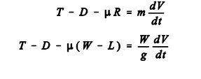
- Equating both equations:
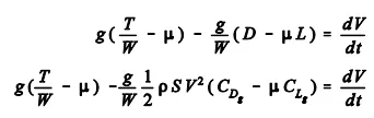 CDg is drag coefficient and CLg is lift coefficient.
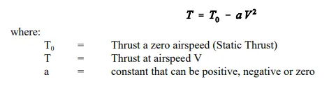
 - The assumption is made that thurst varies with airspeed, thrust is given by:
- Substituting the above equation in rate of change in velocity:
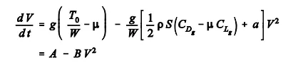
- The above equation gives the acceleration of plane and account for the power required to accelerate.
- Tyre design:
- Airplane tyre are an important part of an airplan which is crucial for safety. It provides the necessary traction for take-off acceleration and braking after touch-down. It provides necessary cushioning effect for passenger comfort and components' safety by absorbing the touch-down shocks.
- The number of tyres on an airplane depends on its weight. Higher the weight, more the wheels for uniform distribution of aircraft weight on the wheels. Tyre sustains the plane weight during parking, taxiing, take-off roll and landing rollout.
- It consists of the following components:
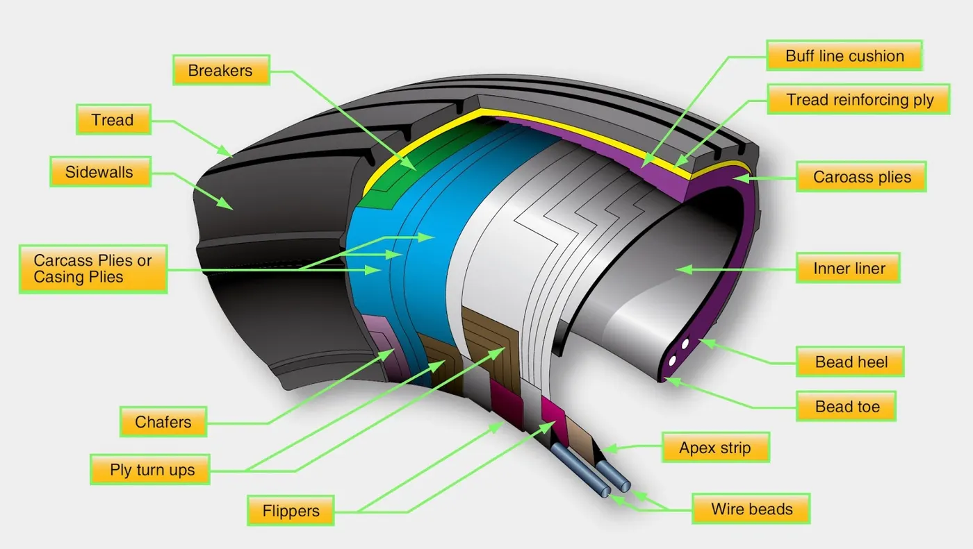
- Carcass plies: It is used to form the tyre. It consists of layers of plies, a ply is nylon fabric layer sandwiched between the rubber layers. The plies are anchored by wrapping them around the bead on both sides to form ply turn-ups
- Bead: It provides firm mounting surface for tyre on the wheel rim. Beads are made of high-strength carbon steel wire bundle encased in rubber. Bead transfers the impact load and deflection forces from the tyre to the wheel rim. Apex strip is the additional rubber around the bead to anchor the ply turn-ups. Flippers are the layer of rubber and fabric around the bead to insulate carcass plies from beads and increase tyre durability. Chaffer is layer of rubber and fabric laid over the outer ply to protect the carcass from damage during mounting and demounting of the tyre.
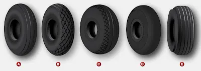
- Tread: It is the compound of rubber that forms the crown of tyre. It is a pattern on the periphery of the wheel to provide strength, durability and resistance against heat, abrasion, cracking and firm grip on wet roads. Various tread patterns can be seen in the adjacent picture. Figure A is a ribbed tread design for paved runways. B is diamond tread designed for unpaved runways. C is the combination of ribbed tread at center and diamond tread at the edges for all weather condition. D is smooth tread for old and slow aircraft without brakes for stopping. E is chine tread that is used in nose gear, used in jet engine with fuselage mounting airplanes to deflect the water on runways from engine intake.
- Side wall: It is the tyre component that protects the carcass plies and negative impacts of ozone. Inner side wall is covered with inner liner. The inner liner is thin in the case of tube-type tyre to protect tube from chaffing on the carcass ply. The inner tube is thicker in the case tubeless tyre so that it is less permeable as it contains the nitrogen gas. However some gas seeps through the carcass and hence vent hole is provided at lower portion of outer sidewall that releases this trapped gas.
- Tyre pressure:
- The tyre is inflated according to the aircraft manufacturer's maintenance manual. The tyre is not inflated directly according to the sidewall information or how the tyre appears. The tyre pressure in unloaded condition and loaded condition can vary as much as 4% .
- Under-inflated tyre can flex beyond the design limits of tyre. This can weaken the carcass construction and cause internal damage that is invisible externally.
- Tyre pressure changes ccording to the ambient temperature. For every 5 degree Fahrenheit change in the temperature, the tyre pressure changes by 1%. If the airplane is flying to colder ambient temperature, then the tyre might be in under-inflated condition. This problem is overcome by over-inflating tyres at hotter ambient temperature departure regions. But this infltion is made sure to be in design limits.
- The aircraft tyre pressure is checked 3 hours after landing so that it cools to ambient temperature. The manufacturer of tyre provides table of appropriate pressure at different ambient temperature.
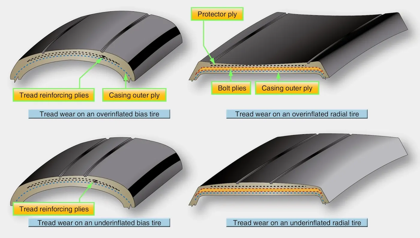
- Under-inflation of tyre causes uneven wear of tread and premature replacement of tyre. It causes the sidewall to be pinched between wheel rim and runway. It causes the slip of beads on the rim.
- Over-inflation causes tread wear at the center of tyre periphery and the tyre is not completely in touch with ground. Under-inflation causes tread wear at shoulders of tyre.
- Rolling resistance:
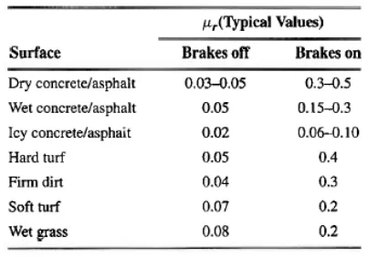
- Rolling resistance is the force opposing the motion of airplane on the ground when the tyres are in touch with the runway. This force depends on the rolling resistance co-efficient, weight of aircraft and the lift forces acting on the aircraft. The rolling resistance is not constant, because as the velocity changes during take-off roll and landing rollout, the lift force varies accordingly which impacts the normal force acting at the tyre-road interface.
- The rolling resistance coefficient depends on the nature of tyre-runway nature as shown below:
- Braking force:
- During the landing roll-out or rejected take-off, the airplane is required to decelerate and stop in a smooth way. Three airplane components can be used in coordination to generate required braking force. Those components are engine, brakes and mechanical spoilers. Braking force required to stop airplane is directly proportional to its weight.
- Engine: The engine thrust lever is put to idle position to reduce the forward moving thrust to zero. Due to inertia, the plane still keeps moving in the same direction. This can be overcome by putting the engine in reverse thrust or reverse propeller pitch mode. Reverse thrust is used only at high speeds when the brakes cannot generate sufficient force. Once the airplane groundspeed reduces sufficiently, thrust lever should be put to idle position so that engine don't consume foreign object debris.
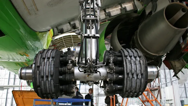
- Hydraulic Brake: The wheel brakes depends on the weight on the brake enabled landing gear, tyre tread condition, runway condition, tyre pressure.
- Break wear and brake temperature should be within the limits to apply the wheel brakes.
- It consists of anti-skid unit that modulates the hydraulic fluid flow to slave cylinder so that braking force is within the maximum traction available at the surface.
- It also consists of Auto brakes with pre-selectable constant rate of deceleration between 3 to 6.
- Mechanical spoilers: It consists of components like wing upper surfaces and tail cone. These components increase the aerodynamic drag and increase the downward force on the landing gear for more traction and more effective braking.
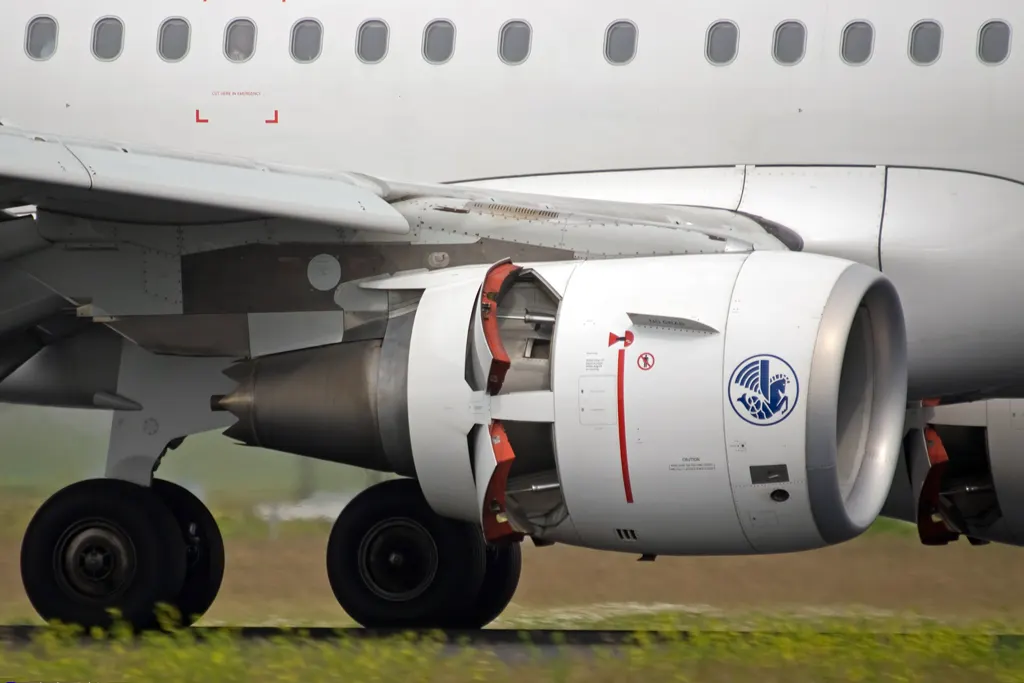
6. A. Force and power calculation to push an aircraft by towing vehicle:
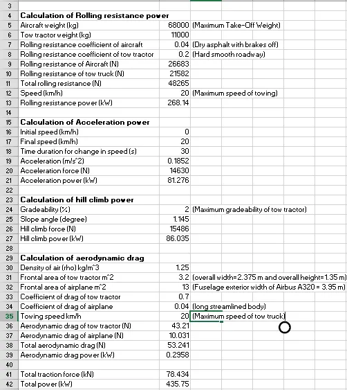
The assumed aircraft and tow tractor are given in the excel file.
Rolling resistance, hill climb resistance, acceleration and aerodynamic drag are taken into consideration for power calculation.
The following formulae are utilized to calculate various forces:
Rolling resistance `F_r=mu_(rr)*W`;
where `mu_(rr)`: rolling resistance coefficient and W: is the weight of the vehicle;
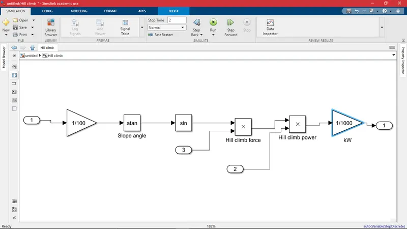
Hill climb resistance: `F_h=W*sin(theta)`
where `theta`: angle of slope of ground and `theta = tan^-1(G)` where G is gradeability
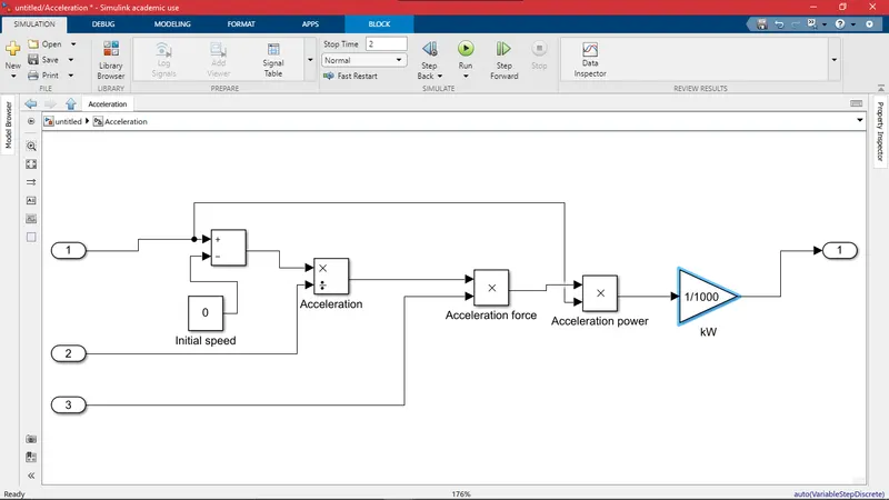
Acceleration `a=(v-u)/t`
where v: Final velocity; u: initial velocity; t: duration of acceleration
Force `F_a=m*a`where m: mass of vehicle
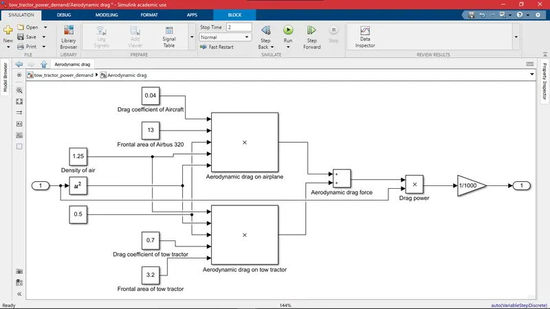
Aerodynamic drag: `F_d=0.5*rho*C_d*A_f*v^2`
where `rho`is density of air; `C_d`is drag coefficient; `A_f`is frontal area of vehicle; v is speed of vehicle
The power is calculated as `P=F*v`where F is corresponding force.
The calculations are performed in excel and the following result is obtained.
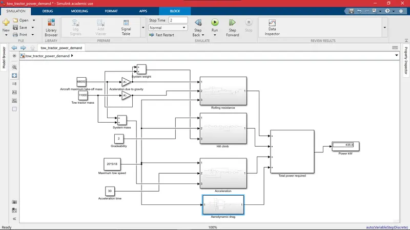
B. Simulink model for calculated force and power:
Overview of complete block:
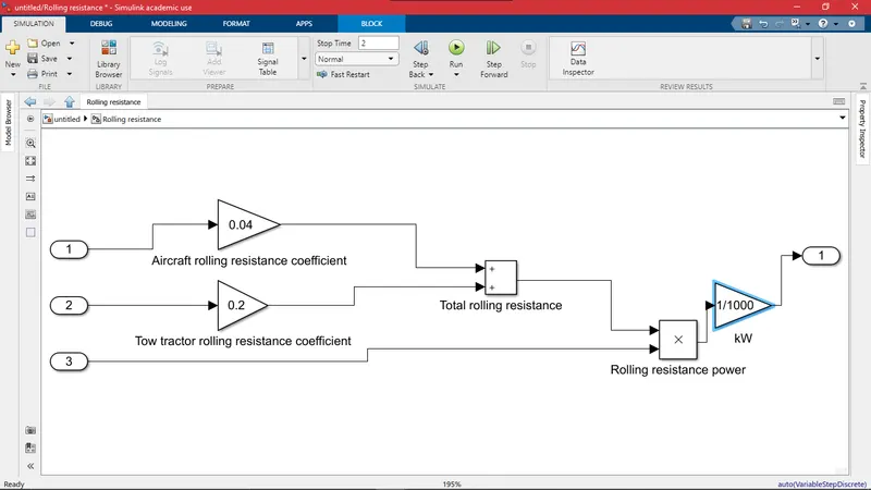
Various subsystems to calculate different power requirements:
7. Designing an eletric powertrain for aircraft towing application and estimation of duty cycle range for aircraft on runway:
Assumed parameters:
| Aircraft model | Airbus A320 |
| Tow truck model | MODEL BA10G40 |
| Aircraft weight | 68000 kg |
| Tow truck weight | 11000 kg |
| Rolling resistance coefficient of aircraft | 0.04 |
| Rolling resistance coefficient of tow truck | 0.2 |
| Tow truck speed while towing | 5 km/h or 1.38 m/s |
| Tow truck maximum speed | 30 km/h or 8.33 m/s |
| Gradeability | 2 % |
| Total traction force required | 78.434 kN |
| Total power required | 435 kW |
| Duration of tow truck application | 1800 s or 30 min |
| Wheel radius of tow truck | 0.537 m |
Torque required at the wheels: `T_w=F_t*r_w=78434*0.537=42119 N-m`
`Total energy required for towing application: `E=P*t=435*0.5=217.5 kWh`; This indicates the battery capacity for tow tractor.
Selection of motor:
From the above assumed parameters and calculations of torque and power, it is inferred that tow tractor is low speed and high torque application. So the motor that best suits this application is Permanent magnet synchronous motor. This motor is capable at providing very high torque at very low speeds. Since the tow tractor is used for short duration of time, motor with forced ventilation is selected rather than water cooled. From the below list of motors, the motor with power output close to required power of 435 kW is 471 kW with positive tolerance.
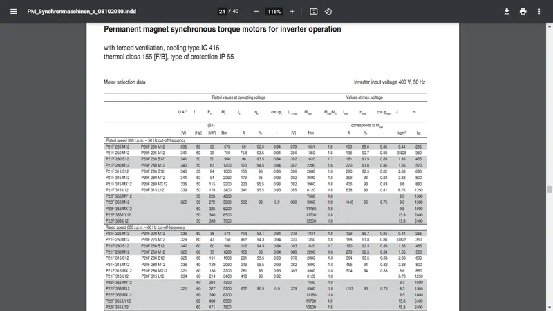
This selected motor: P22F 355 L12
Motor rated torque: `T_m=7500 N-m`
Efficiency of the motor: `eta=96.5 %`
Rated current : `I =1257 A`
Maximum voltage : `V=400 V`
Weight of motor: 2400 kg
Calculation of gear ratio: `G=T_(required)/T_(m)= 42119/7500 ~= 6`
Gear ratio is selected to be 6.
We know that: `F_(traction)=P/v_w => T_m*G/r_w = (P*G)/(omega_m*r_w) => T_m=435000/omega_m`
The above equation is the motor characteristics.
Powertrain design:
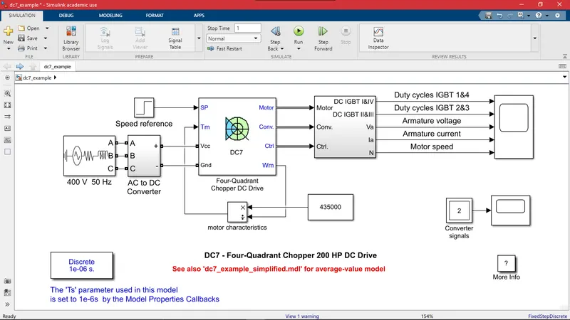
The above figure shows the powertrain arrangement of tow tractor for towing aircraft. The battery source is displayed at the left. The battery parameters are the maximum voltage value of the selected motor. The motor characteristics is implemented as calculated above.
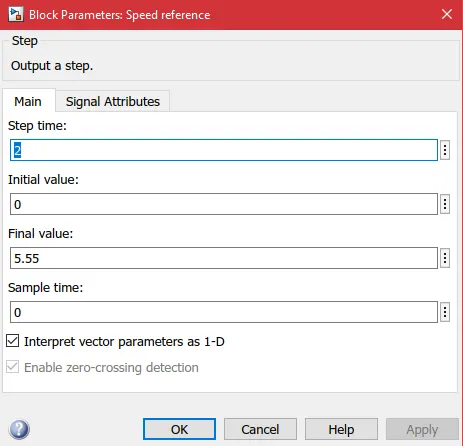
The tow tractor speed is put into the speed reference block parameters. Final speed value is taken as the maximum speed of tow tractor: 20 km/h. And the tow vehicle is initially in standstill position, so initial value is 0.
Duty cycle:
Duty cycle is an important parameter for the power electronics switch between the battery and motor. The motor is required to be supplied with gradually changed voltage values but if the batter is directly connected to the motor, motor receives full battery voltage and runs at rated speed instantaneously. So in order to regulate the voltage in gradual manner power electronics switches come into picture. Duty cycle is the ratio of amount of time the switches are required to be ON to the total time period (sum of ON and OFF period). Duty cycle can be calculated with the ratio of power supplied to the motor (or output power of power electronics circuit) to the power supplied by the battery (or input power to the power electronics circuit).
Required output power of the motor for towing application at highest speed of 20 km/h: `P_(req)= 435 kW`
Input power to the motor to obtain required output considering the losses in the motor: `P=P_(req)/eta_m = 435/0.965 = 450.77 kW`
So the output power of power electronics circuit is `P_o=450.77 kW`
Assume battery source parameters such that it is capable of providing maximum power that the selected motor can withstand. So let the maximum voltage and current values be the parameters of the battery.
Battery voltage: `V_(bat)=400 V`
Battery current: `I_(bat)= 1257 A`
Battery power: `P_(bat)=V_(bat)*I_(bat)=400*1257=502.8 kW`
So the Input power of the power electronic circuit is `P_i=502.8 kW`
Duty cycle: `D=P_o/P_i = 450.77/502.8 = 0.896`
So the duty cycle range for towing aircraft from zero to highest speed is 0% to 89.6%
B. Design parameters in excel sheet is attached.
Reference: