Final Project: Electric Rickshaw modelling
Aim: To create a MATLAB model of an electric rickshaw having rear wheels driven by Permanent Magnet Brushed type motor with assumed efficiency points of motor controller and motor. And to simulate the model for three standard driving cycle while tracking the battery energy consumption, motor and controller temperature for 100 km constant speed driving at 45 kmph.
Theory:
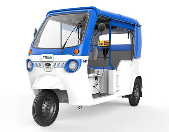
This image depicts an electric auto rickshaw. An autorickshaw is a vehicle with three wheels, two wheels are the rear axle and one wheel at the front. Electric autorickshaw is widely accepted as an alternative to petrol, diesel or CNG fueled vehicle. It is the leading short-distance travel solution in India.

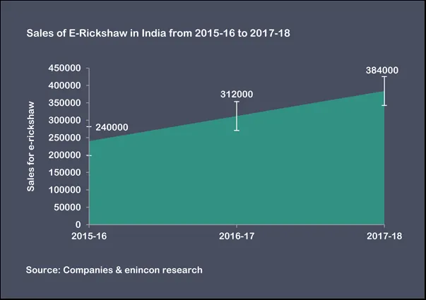
As shown in this graph, the market share of E-rickshaw is widening. The vehicle body is made of mild steel. It has a differential at the rear axle. In the Indian version of the E-rickshaw, the motor is rated at 48 V. It also consists of a controller unit.
Power requirement calculation:
Assumptions regarding the vehicle, environment and road profile are made and the maximum traction power required to propel the vehicle is calculated in Excel.
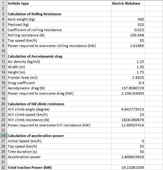
The traction power required is approximately 20 kW. Hence the motor and battery need to be selected in such a way that this requirement is fulfilled. Popularly 48 V rated motor opt for E-rickshaw in India. However, for this modelling, the motor rating is chosen to be 150 V.
Modelling:
Vehicle Body:
- Tire:
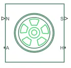
- This is the Simulink block of the tire that represents only the longitudinal behaviour of the tire.
- This block has multiple connections: Port A represents the axle connection that determines differentiates the front and the rear axle tires; Port H represents the Hub that ensures the thrust developed at the tire-road interface is applied to the vehicle; Port N represents the normal force acting at the tire-road contact points; Port S is for accounting the tire slip
- For electric autorickshaw, three such blocks are taken: two tire blocks at the rear axle and one tire block at the front. The axle ports of two tires are connected to represent the rear axle of an autorickshaw. The hub ports of all tires are interconnected.
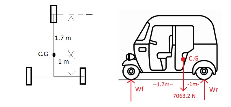
- Calculation of static load on each wheel: Wf is the load on the front wheel, Wr is the load on rear axle and at Center of Gravity, the weight of the vehicle body acts.
- Taking the moment of inertial at the front wheel: `W*1.7=W_r*(1.7+1) => 7063.2*1.7=W_r*2.7 => W_r=4447.2`N
- The load on the front wheel is calculated by taking sum of vertical forces : `W_f+W_r=W => W_f=7063.2-4447.2 => W_f= 2616 N`
- The load on the rear wheels is equally distributed: `W_(rw)=W_r/2=4447.2/2=2223.6 N`
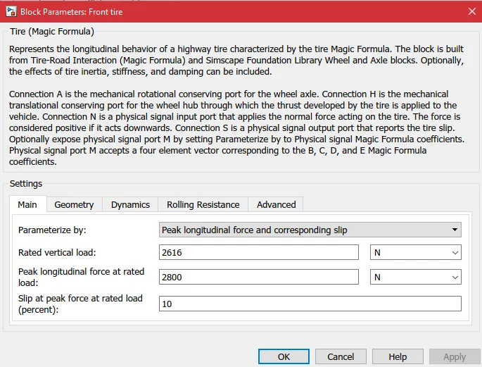
- This is the block parameter of the front wheel
- The rated vertical load is set as per the calculation. Static vertical load at the front wheel is 2616 N and due to dynamic load transfer during braking, peak load is set to 2800 N.
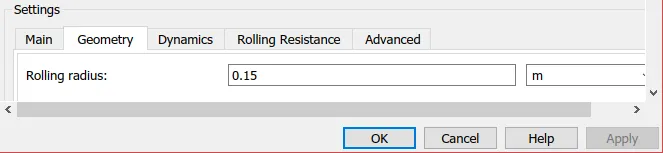
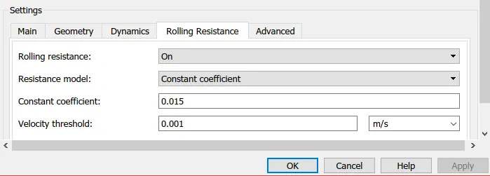
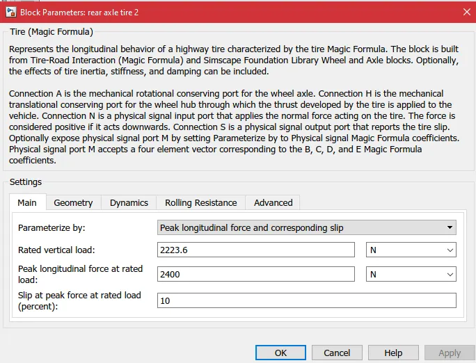
- This is the block parameter of the rear tire. static vertical load is set to 2223.6 N as per calculation and peak load is set to 2400 N given to dynamic load transfer during acceleration.
- Vehicle body:
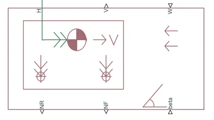
- This is a Simulink block of a vehicle body with two axles and having only longitudinal motion. It takes into account the vehicle body parameters and also the environmental factors
- The multiple connections of the block are: NR and NF ports are for applying normal load on the rear and the front wheel axle respectively; V and W port is for vehicle and wind velocity respectively; beta port is to take the road inclination into account; H port is the hub connection from tires, to apply the thrust from wheels to vehicle body.
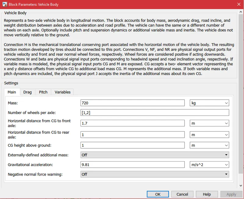
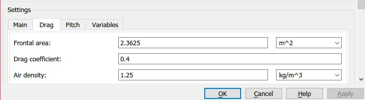
- The block parameters of the vehicle body as shown. Mass is set to the gross weight of the vehicle that includes kerb weight (empty vehicle) and payload weight (driver and 3 passenger weight). C.G location is set to as per the design shown above.
- Gear:
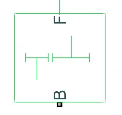
- It is the simple gear block required to sit between the motor and wheels.
- B port is the base: the input shaft to take kinetic energy from motor; F port is the follower: gearbox output shaft to transfer the motor kinetic energy to wheels.
- The gearbox output shaft F is connected to the axle connection of the rear tires.
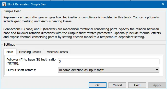
- In the block parameters, the gear ratio is set to 3.
- Vehicle body subsystem:
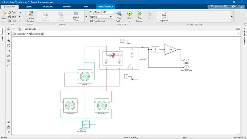
- The subsystem of the vehicle body is created, and it has a vehicle body, tires, and a simple gear block.
- The connections between the various blocks are made as shown above
- The beta and wind velocity port of vehicle body is connected to a constant block of value-0. Hence road inclination and wind velocity are not taken into account.
- This subsystem has motor torque as input port and vehicle velocity and distance as output ports.
- The velocity port of the vehicle body is connected to an integrator block. This block integrates velocity in m/s to calculate the displacement in meters. This displacement is converted to kilometer format by using a Gain block with gain: 1/1000.
DC motor:
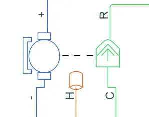
- This is brushed type DC motor block that represents the electrical and torque characteristics of the DC motor
- This block accepts the electric current from + port to - port. Port R represents the rotor and C represents the case/stator.
- H is the thermal port that is hidden by default. To enable this, right-click over the block and then in the context menu select Simscape>Block Choices>Show thermal port. This port determines the heat generated by the copper losses.
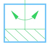 This is the mechanical rotational reference. It represents the fixed frame and is connected to the component that is fixed to ground or stationary in nature.
- Hence this block is connected to C port of DC motor so that the torque developed in the rotor is with reference to the fixed stator (port C).
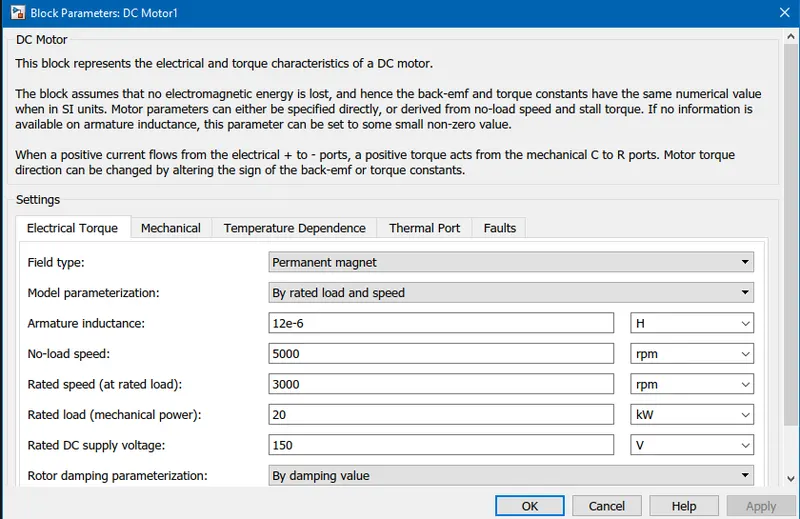
- As per the model requirement of a Permanent magnet brushed type motor, permanent magnet is chosen as the field type
- Model parameterization is set so that only motor load and speed needs to be specified, which the model converts into equivalent circuit by calculating the rated torque of the motor.
- Since the electric autorickshaw is required to have a high speed of 55 kmph, the rated motor speed is set as per the requirement. Calculation: The longitudinal velocity of the vehicle is converted into angular velocity. We know: `omega_(tire)=v_(tire)*r_(tire)=(55*5/18)/0.15 = 101.85`rad/s; The angular velocity of the wheel is converted into RPM of wheel: `N_(tire)=60*omega_(tire)/(2*pi) => N_(tire)=60*101.85/(2*pi) => N_(tire)=972.48`RPM; The rpm of wheel is converted into rpm of motor using the gear ratio (G) at rear axle: `G=N_(mot)/N_(tire) => N_(mot) = G*N_(tire) = 3*972 = 2916`RPM. So the motor rated speed is rounded off to 3000 RPM and the no-load speed is set to 5000 RPM.
- In the Excel total traction power calculation of the electric autorickshaw, the maximum power requirement of the vehicle was determined to be approximately 20 kW. Hence the rated load is set to 20 kW.
- Rated voltage of the motor is set to 150 V.
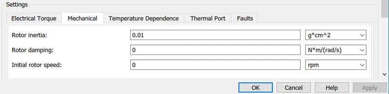
- The mechanical parameters are set to default

- Measurement temperature is set to room temperature. It is the value at which resistance value is defined.

- Thermal mass is set to 20000. It means that 20 kJ is the energy required to raise the motor temperature by 1 K.
- Initial temperature of the motor is set to room temperature.
Motor drive:
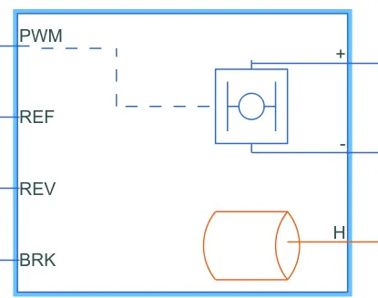
- This is the H-bridge motor drive block that interfaces the battery and the motor.
- If the battery is directly connected to the motor, the motor runs at rated speed without any regulation of speed. To control the speed of the motor, the supply voltage from the battery needs to be controlled. Hence, an H-bridge motor drive is a block that manipulates the battery supply voltage to suit the driver requirements. H-bridge can increase the motor speed by increasing the duty cycle of applied voltage, decrease the speed by decreasing the pulse width/ duty cycle of applied motor voltage, brake the motor by short-circuiting the output terminals and reverse the motor rotation direction by reversing the output polarity.
- This block has four input ports: PWM port accepts the acceleration command from the driver; REV port accepts the acceleration command in the reverse direction; BRK port accepts the brake command or deceleration command from the driver. And the block has two output terminals that give out the manipulated battery supply voltage to the motor.
- The thermal port H is hidden by default. It is enabled by right-clicking over the block and then in the context menu select Simscape>Block choices>Show thermal port option. This port is required to measure the temperature of the motor drive during simulation. This port determines the heat generated at Bridge-on resistance and diodes to calculate the temperature rise of the overall motor drive.
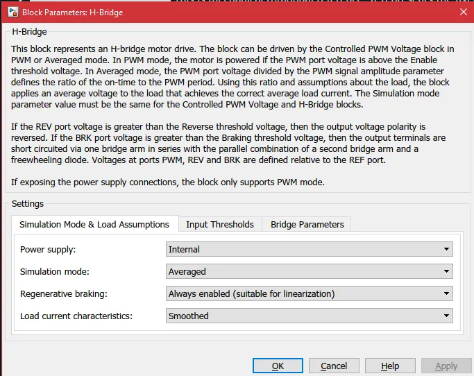 This is the H-bridge block parameters
- Power supply is set to internal; In this case, H-bridge motor drive does not require the external battery for power supply, but the voltage is internally produced
- Simulation mode is set to averaged; The PWM mode is time-consuming while the averaged mode is faster in simulation; In Averaged mode, PWM port voltage is divided by the amplitude of the PWM signal to obtain the duty cycle.
- Regenerative mode is enabled; This ensures that motor kinetic energy during braking is converted back to electric energy and fed back to the batter. In this case, H-bridge motor drive works in buck mode.
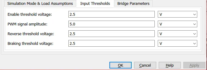
- These are the input threshold values of the H-bridge motor drive.
- PWM signal amplitude is set to 5 V and it determines the duty cycle
- The reverse threshold voltage is a reference voltage, if the REV port voltage exceeds this threshold, then H-bridge works in reverse mode.
- Braking voltage is set to 2.5 V and it also serves as reference voltage. If the BRK port voltage transcends this threshold then H-bridge implements motor braking.
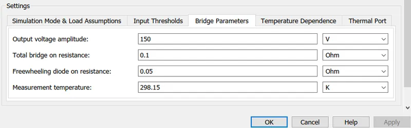
- These are the bridge parameters. The output voltage amplitude is set in such a way that it matches the rated voltage of the motor. Since 150V is the rated voltage of the motor, same output is required across the output terminals of motor drive.
- The measurement temperature is the temperature at which resistances on the block parameters are defined. This value is default.
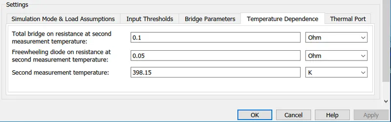
- In the temperature dependence tab, the values are default. The second temperature is the temperature at which the resistance values are defined.
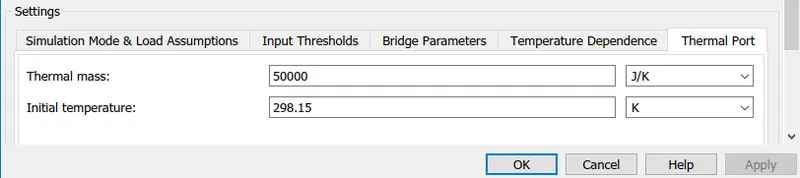
- Thermal mass is the amount of energy (in joules) required to raise the temperature of unit mass by 1 K.
- The initial temperature of the motor drive is set close to room temperature.
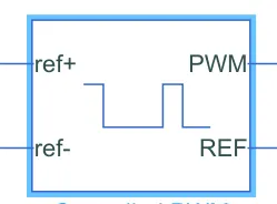
- It is a Controlled PWM block that creates a pulse width modulated signal between the PWM port and REF port. PWM output voltage is equal to the set amplitude when the input ref+ signal is high and PWM output voltage is zero when the ref+ input signal is low.
- This block interfaces between the motor drive PWM port and acceleration pedal (acceleration control signal) of the controller.
- This block converts the acceleration requirement/command from the driver into electric pulses.
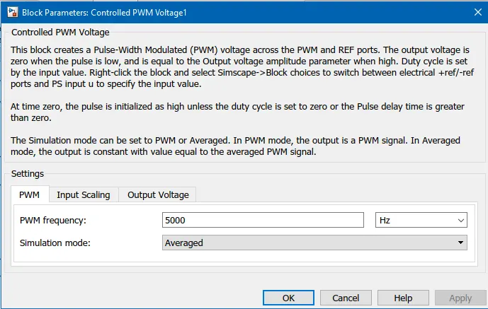
- The output PWM signal has a frequency of 5000 Hz or a time period of 0.0002 seconds.
- The simulation mode is set to averaged so that simulation is faster. In this mode, the output of this block is the average value of generated PWM output signal.
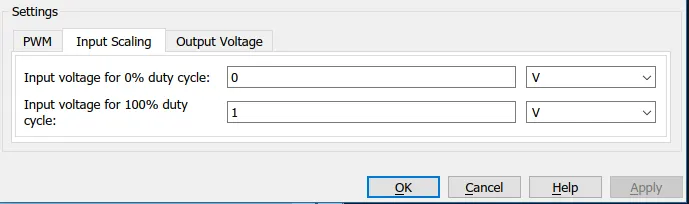
- This setting says that when the input signal is 0, that is when the acceleration command is 0 (no acceleration required), PWM output signal has a 0% duty cycle
- When the input signal is 1 or the acceleration command is 1 (full acceleration required), PWM output signal has 100 % duty cycle.
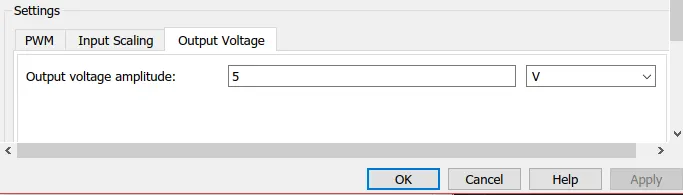
- The maximum amplitude of the PWM signal is set to 5V.
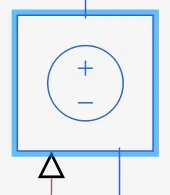
- It is a Controlled voltage source block that is used to power the PWM port and BRK port of H-bridge motor drive. It acts as an ideal voltage source.
- It takes the acceleration command and deceleration command from the driver as input and gives output as high or low signal to activate acceleration or braking through motor drive.
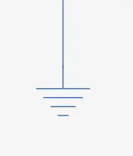
- It is an electrical reference port that represents electric ground.
- The negative terminal of motor, REV and REF port of motor drive, the negative terminal of controlled voltage source are connected to this block.
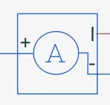
- This is a current sensor block. This block is used to know the amount of current consumed by the motor.
- This block is connected between the positive terminal of motor drive and motor
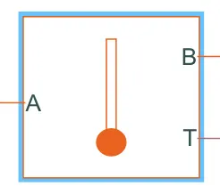
- This is the temperature sensor block. It measures the temperature in the thermal network
- Port A and B are input ports that are connected to different blocks and T is the temperature output port. This block measures the temperature difference between the connected blocks and gives the same output through T port.
- This is the thermal reference block. The temperature of this block is absolute zero.
Temperature measurement subsystem:
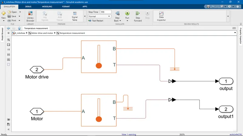
- The motor drive and motor thermal ports are connected to different temperature sensors at Port A and Port B is connected to the Thermal reference block. The temperatures of motor and drive are given out as output from the subsystem.
Motor and motor drive subsystem:
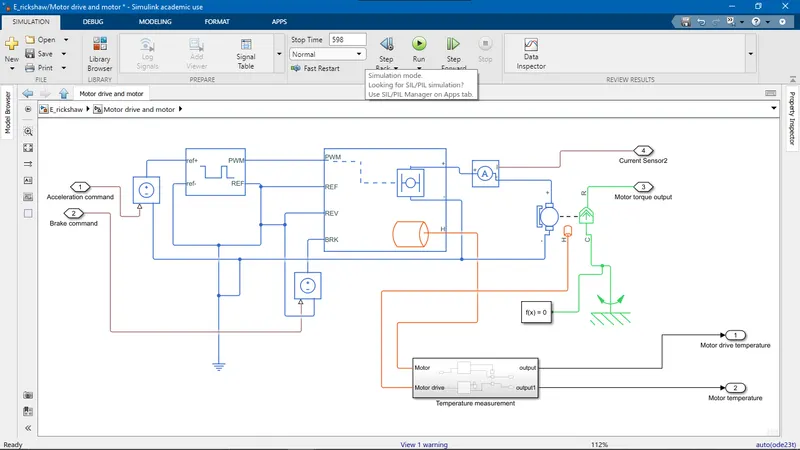
- Acceleration command from the driver block is connected to the controlled PWM block. Here the duty cycle for acceleration voltage is generated. This is then connected to PWM port.
- Deceleration command from the driver block is connected to the controlled PWM block, where the duty cycle for braking voltage is generated. This is then connected to BRK port of motor drive.
- This subsystem gives out temperature, motor torque and current consumed by the motor as output.
Battery:
In this model, the battery is not used to power the motor but to stimulate the battery characteristics. The H-bridge motor drive is self-powering and does not need external power supply. But the battery is needed to track the State of Charge when the motor is run as per the drive cycles. The various blocks required to track battery SOC are:
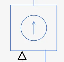
- This is a controlled current source block. It represents an ideal current source.
- The terminals of this block are connected to the battery. The input port is connected to the current sensor output port.
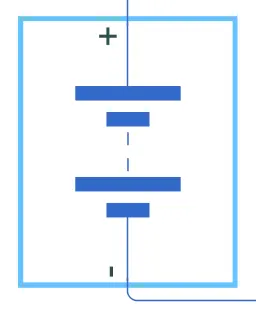
- This is the battery block. The battery terminals are displayed on either side for the connections.
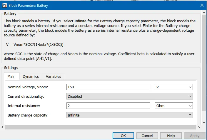
- The charge capacity is selected as infinite, hence the battery voltage is independent of the battery state of charge and constant. The voltage is set to 150 V to match the motor requirement.
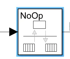
- This is the Rate Transition block. It converts the data from input block rate to output block rate.
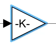
- This is the Gain block.
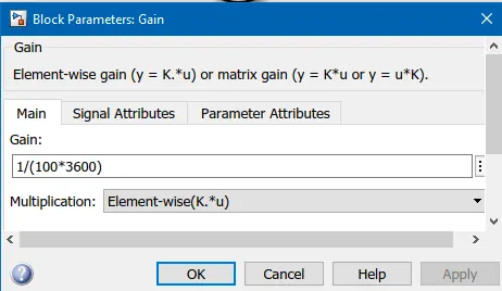
- This block takes the current in Amperes as input and multiplies the charge capacity in Ampere-hour of the battery to obtain the instantaneous State Of Charge as output.
- The gain value specified in the block is the inverse of charge capacity. The battery is assumed to have a charge capacity of 100 Ampere-hour. It is converted to Ampere-second by multiplying with 3600.
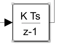
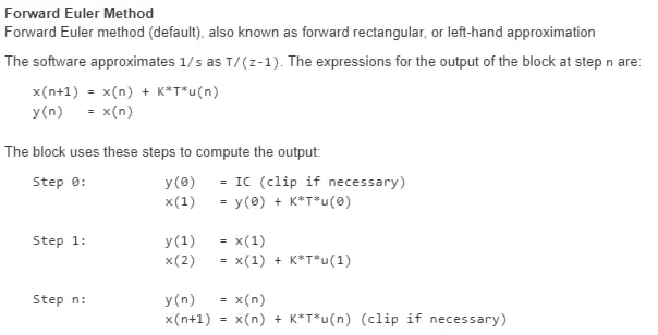
- This block is called a discrete-time integrator block. This block performs discrete-time integration or accumulation of signal.
- The state of charge value passed by the gain block has discrete value: fixed value at a different point in time. To accumulate the SOC value throughout the simulation, this block is required.
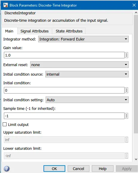
- The integration method is set to forward Euler. In this method, accumulation is done as follows:
- SOC calculation subsystem:
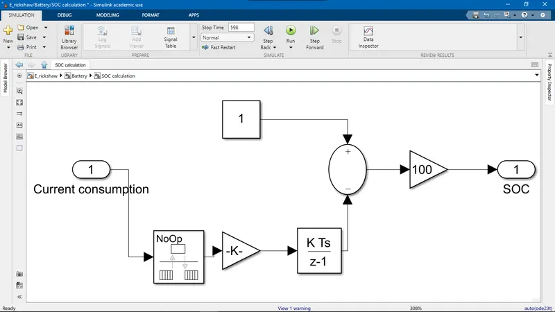
- The block connections are done in this way. The accumulated SOC data is increasing in nature and is valued between 0 and 1. To show that battery SOC is decreasing, the output of the integrator block is subtracted with Constant 1 block with Minus block. The Gain-100 block is used to show SOC in a percentage format.
- Battery subsystem:
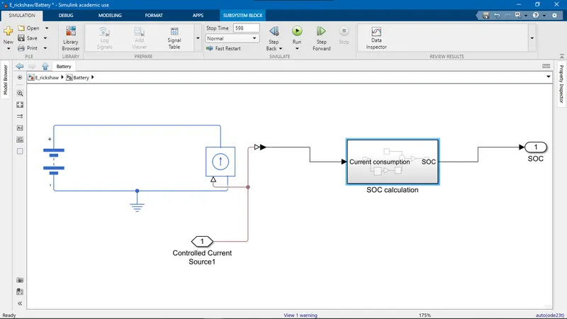
- The positive terminal of the motor is connected to the positive of the Controlled current source and negative terminal is connected to the electrical reference block.
- Current consumption is taken as input to this subsystem and the same is provided as input to SOC calculation block and battery SOC is taken as output.
Reference input:
Selection of three standard drive cycle:
Criteria of selection of the drive cycle is: the maximum speed of E-rickshaw is set to 55 kmph, hence the drive cycle speed should be within 55 kmph peak vehicle speed. Based on this criterion, the following drive cycles are selected:
- Manhattan Bus Cycle:
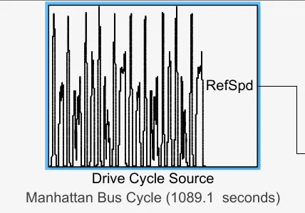
- This drive cycle runs for a time period of 1089.1 seconds and has a maximum velocity of 11.5 m/s or 41.4 kmph.
- NYCC drive cycle:
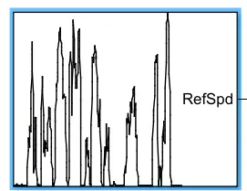
- The drive cycle runs for 598 seconds and the maximum speed is 13.38 m/s or 44.56 kmph.
- Artemis urban cycle:
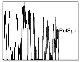
- It has a time period of 993 seconds and has a peak velocity of 15.88 m/s or 57.16 kmph.
- Wide-open throttle:
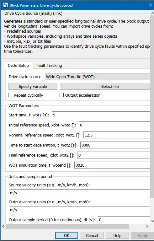
- This drive cycle is selected to simulate the E-rickshaw to run for 100 km at a constant speed of 45 kmph.
- Nominal reference speed is set to 12.5 m/s or 45 kmph, it represents the peak constant speed at which the vehicle is required to run.
- Initial reference speed is the starting speed of the vehicle.
- For a vehicle to run at 45 kmph for a distance of 100 km, it requires to run for 2.22 hours or 8000 seconds; calculated based on the formula: `time=(distance)/(speed)`; Hence time to start deceleration is set to 8000 seconds and simulation time is set slightly greater than that.
Multiport selection:
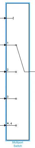
This block is a multiport switch. It is used to connect multiple choice inputs but the output is one out of the inputs. It acts as a switch for multiple options. The inputs, in this case, are the four drive cycles selected. The inputs are numbered and the initial input to this port is a constant block. The constant block value is based on this numbering, and the switch gives the corresponding drive cycle as output to driver block. In this above block, the constant block value is set to 1, hence the drive cycle one is connected to output port.
Creating a subsystem:
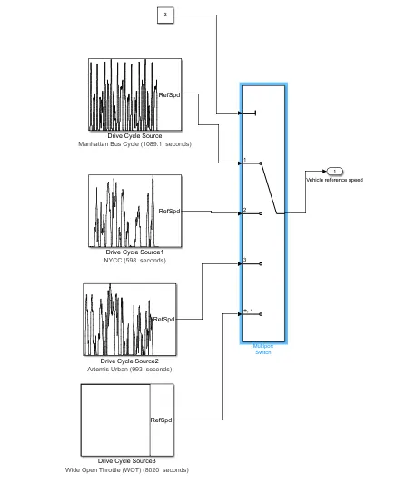
The reference input block is designed in the way displayed above.
Controller:
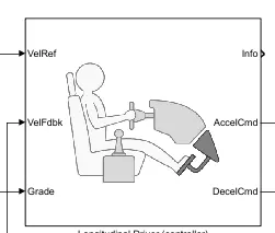
- It is a Simulink library block from the powertrain blockset called the longitudinal driver. The prime function of this block is speed control.
- It is a speed tracking controller with three inputs. VelRef port accepts the reference speed of the vehicle that is defined within the drive cycle. This input is obtained from the reference input block. The controller objected is to match this speed.
- VelFdbk port accepts vehicle feedback speed. It is the actual speed of the vehicle generated by the vehicle body block. It is an essential input for the controller for to make sure that the reference speed and actual speed are matched. The controller calculates the difference between reference speed and actual speed. This difference is converted to an error signal that defined the corrective actions taken by the controller.
- Grade is the third input port that defines the road slope. For a positive slope, the vehicle needs to put in higher effort to achieve the same speed and for a negative slope, much lower effort is required. Based on the grade, magnitude of the corrective actions of the controller is determined.
- AccelCmd is an output port that gives out an acceleration command. It is a corrective signal valued between 0 and 1. 0 corresponds to no acceleration and 1 corresponds to full acceleration just like the complete depression of acceleration pedal by the driver. For the positive error between VelRef and VelFdbk inputs, AccelCmd is greater than 0. To increase the vehicle speed to match the reference speed, the controller provides an acceleration command.
- DecelCmd is also an output port that gives out the deceleration command. If belief and VelFdbk have negative error, DecelCmd value is greater than 0 which is equivalent to depressing the brake pedal to slow down the vehicle. And if the error signal is positive, DecelCmd is valued 0 or no deceleration command is given by the controller.
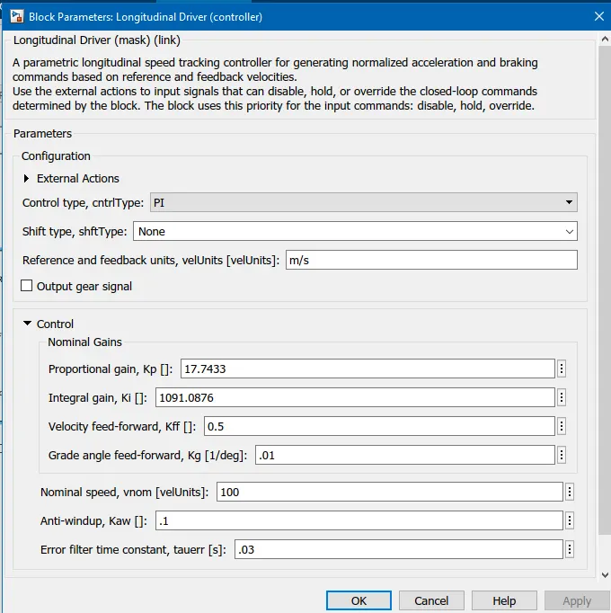
- These are the parameters of the Longitudinal driver block
- The control type is PI (proportional-integrator). The proportional gain and integral gain are set as shown. Proportional gain and integral gain setting reduce the steady-state error, rise time and settling time while keeping the maximum overshoot in check.
- Shift type is set to none. It represents that this block doesn't take transmission into account. It is set to none since reverse is not required.
The transfer function used in the longitudinal driver block is shown below.
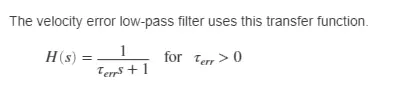
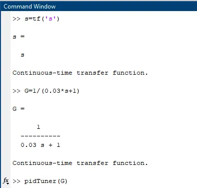
From the block parameters, the default error filter time constant is set to 0.03. This transfer function is created in the command window and the pidTuner() command is used to find optimized proportional gain and integral gain values.
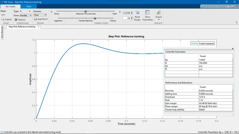
The pidTuner user interface window is shown above. Step response of the transfer function is displayed. It has a peak overshoot and rise time and settling time can be improved. The response time slider is moved towards the right to make the step response faster and transient behavior slider is also moved to the right to make the response more robust and reduce the steady-state error.
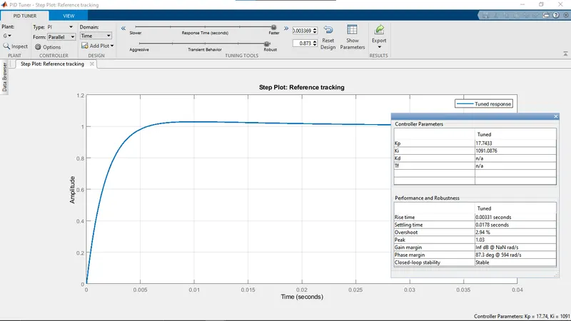
The optimized step response can be observed in the image above. The proportional gain value is increased to 17.7433 and the integral gain value is increased to 1091.08676 to make the response faster and more robust. The same values are set in the Longitudinal driver block parameters.
E-rickshaw Model:
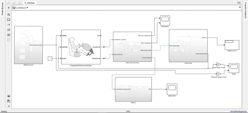
- This is the closed loop control system of the E-rickshaw. Drive cycle acts as the reference signal. The longitudinal driver block is the controller. Motor drive and motor block is the plant of the control system. Vehicle body block is the actuator. The feedback signal is obtained from the vehicle body and given to the controller.
- The battery source is not directly connected to the motor but the motor drive. The motor drive in turn supplies controlled power to the motor.
- The reference speed from the drive cycle and actual vehicle speed is converted from m/s to km/h through Gain block and connected to scope.
- The distance output from the vehicle body block is connected to the Display block.
- The battery SOC output is connected to the scope.
- The motor drive and motor temperature output are also connected to the scope.
Simulation and output:
- Manhattan bus cycle:
Speed:
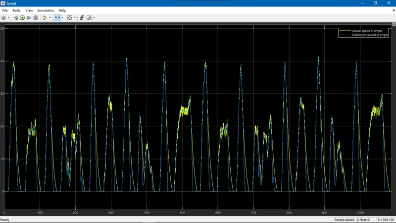
- The vehicle speed output closely follows the reference speed. The modelled E rickshaw can achieve the peaks but the deceleration is slower.
- During this cycle simulation, E-rickshaw runs for a distance of 3.832 km
Temperature:
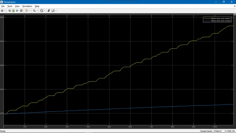
- The yellow line represents motor temperature and the blue line represents the motor drive temperature.
- From initial room temperature, the motor temperature rises to 475 K or 202 oC and motor drive temperature rises to 320 K or 47 oC.
Battery level:
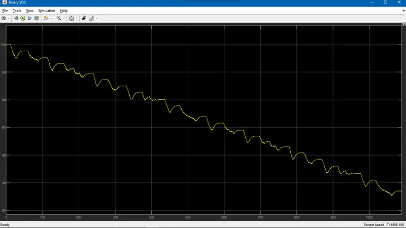
- During this cycle, battery level drops from 100 % to 94.6 %.
2. NYCC drive cycle:
Speed:
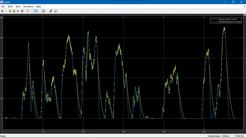
- The actual speed of vehicle closely follows reference speed.
- In this simulation, the vehicle runs for 2.089 km
Temperature:
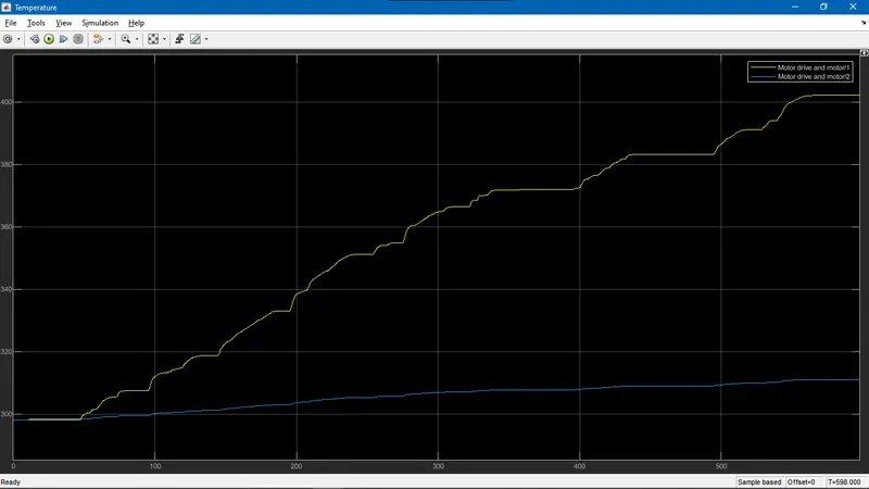
- Motor drive temperature rises to 310 K or 35 oC
- Motor temperature rises to 400 K or 127 oC at the end of drive cycle
Battery energy consumption:
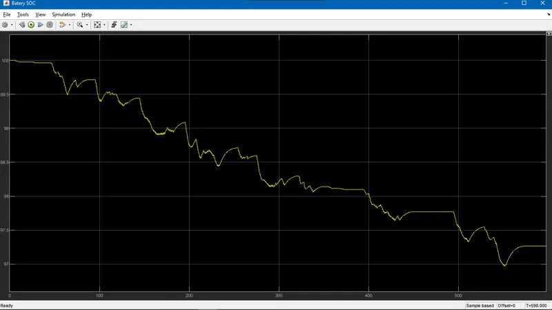
- Battery is fully charged at the beginning of drive cycle and the end of simulation, battery level drops to 97.25 %.
- During the drive cycle, the battery is also charged whenever there is sharp deceleration. This is because H-bridge is configured for regenerative braking (all-time enabled). Hence during deceleration, kinetic energy of the wheels are absorbed by motor working in generator mode. The motor produces current and motor drive feeds back the charge to the battery.
3. Artemis Urban cycle:
Speed:
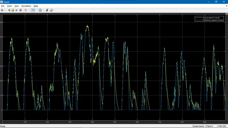
- The vehicle runs for a distance of 5.289 km.
- It can be seen that vehicle is unable to follow steep deceleration. And at some instance, vehicle is unable to reach zero speed whenever steep deceleration is followed by peak acceleration.
Temperature:
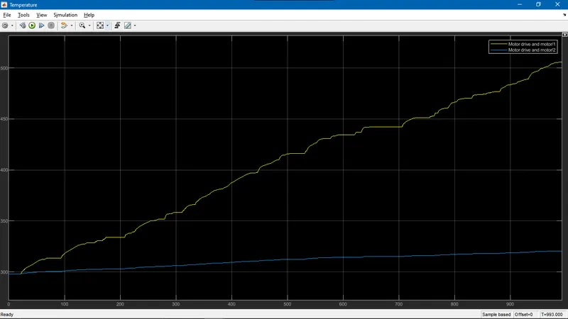
- Motor temperature rises to 500 K or 227 oC. Hence repetitive steep acceleration and steep deceleration have a negative impact due to temperature rise.
- Motor drive temperature rises to 325 K or 52 oC.
Battery energy consumption:
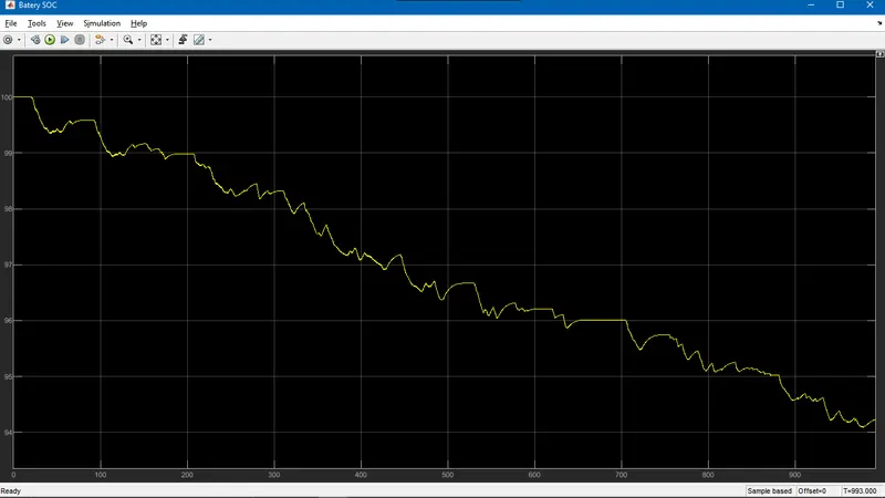
- The battery state of charge drops to 93 % from full charge at the end of drive cycle.
4. Wide-open throttle:
Speed:
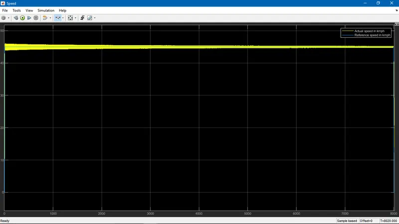
- The thick yellow line represents the vehicle speed. The thickness of the line is due to speed fluctuation. Thus the auto-rickshaw is unable to settle at a constant speed of 45 kmph. The actual vehicle speed oscillates between 43 and 47 kmph. This steady-state error is due to the high value of integral gain. The output speed can be made stable at 45 kmph by reduces the integral gain value.
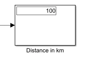
The distance block confirms that the E-rickshaw was able to run for 100 km.
Battery charge consumption:
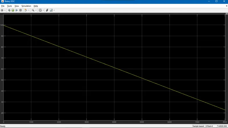
- The battery charge drops to 25 % at the end of 100 km drive.
Temperature:
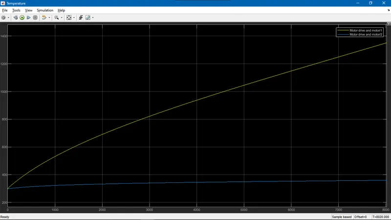
- Motor temperature increases to 1350 K or 1077 oC. This is an unbearable temperature and hints at the thermal runaway.
- Motor drive temperature is stable at 370 K