Week 9 - Project - A pillar Design with Master Section
Introduction:
A-pillar is an important structure of the four-wheeler vehicle. It supports the windshield and roof. It is the first pillar of the vehicle. It connects with the windshield frame, provides groove to the window and connects with the roof. In this project, Class-A surface of the A-pillar is taken as input and Class-B and Class-C surfaces are generated based on Class-A surface. Catia V5 commands such as offset and multi-section are used in the Generative Shape design module to create Class-B surface. Whereas commands like Sweep is used to create Class-C surface. Finally CAD model is created. Draft angle of 0.5-3 degrees is required to manufacture the components using injection moulding process. Major components require a draft angle of 3 degrees while minor attachment features are allowed with draft angle of 0.5 degrees for ease of manufacturing. The draft angle check is performed for the CAD using Feature Draft Analysis tool.
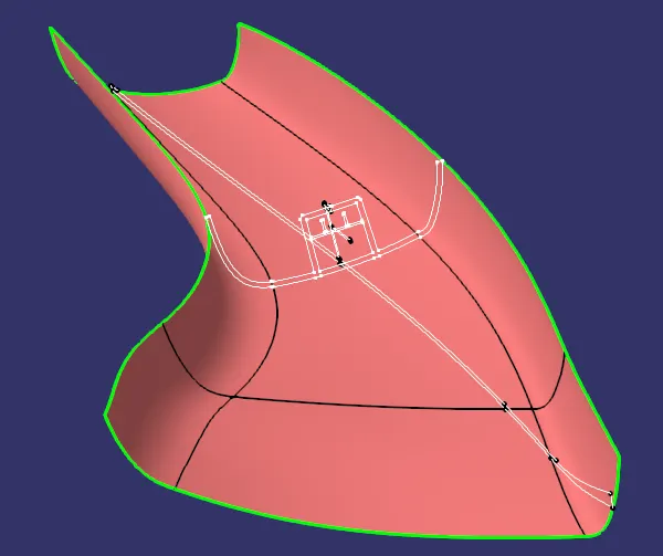
The above image shows the input Class-A surface. Master section is highlighted in white. Master section reveals the details of the component like thickness and dimensions of the B-side features or the attachment features like dog house, rib, flange. The above master section indicates 2.5 mm thickness for the component and for dog house and outer edge fillet radius of 1.5 mm for the dog house. The master section data used to create sketches to generate the surfaces and form the final model.
Procedure:
A. Tooling Axis creation:
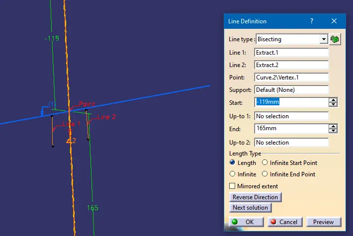
- The vertical sides of the master section are taken as input for tooling axis. Bisecting command of line is used to create tooling axis at the center.
- The vertical sides of the master section that represents the dog house are extracted and and used as reference to create a bisecting line with mid-point as origin of the line.
- This creates a main tooling axis along with the main core and cavity would get engaged.
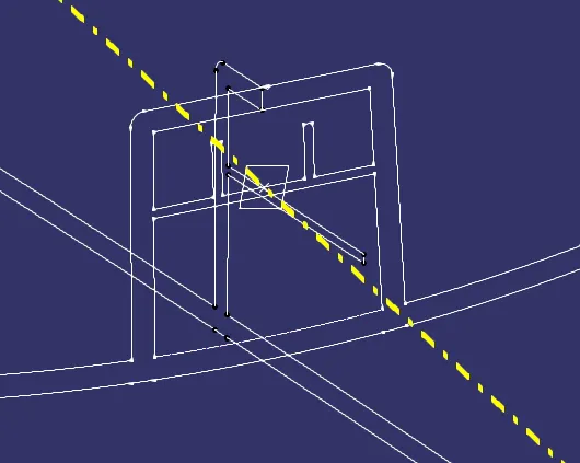
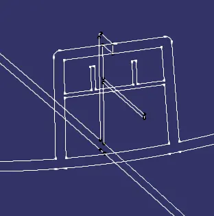
- Side core axis is also based on the master section. A plane is created by using mind-point and horizontal edge of the master section.
- Plane provides a base for side core axis normal to which axis can be created. Mid-point is the origin of the line through which the axis passes.
B. Draft analysis:
Draft analysis is
- Using Customize view command, Final model is put into material mode and the Feature draft analysis command is launched. The compass is set on the tooling axis. The result of draft analysis is attached in the PPT.
- Most of the Class A surface is green as it is clearing the min draft angle requirement of 3 degrees. But the side edge of the Class A surface is found to have negative draft angle of 36 degrees. Hence this surface needs reformation.
- Most of the Class- B surface clears the draft angle requirement except a small portion of the edge that has a minimum draft angle of 2.5 degrees and falls short of 0.5 degrees to clear. However it is acceptable due to minor deviation.
- Longitudinal section of the Class C surface is green while the lateral section is blue. The Class C-surface has a minimum draft of -37 degrees.
- And the dog house feature also clears the draft analysis for the Main tooling axis and Side tooling axis.
Conclusion:
The draft analysis results and final CAD model is shown in the attached PPT.