Week 8 - Challenge 2 - Switch Bezel Design
Switch Bezel Design
Introduction:
The project aims to create a automotive plastic compoenent: Switch Bezel. The class A surface is the input for the project. The given surface is analysed to ideate on the tooling axis based on the direction the part could be ejected from the injecion moulding machine. The tooling axis is used to perform draft analysis for the component to check its conformity with surface draft angle requirements of injection moulding. Then the surfaces of the class A surfaces are extracted and formed at an offset of 2.5 mm to generate class B surface. Furthermore, the boundary of the class A surface is used for class C surface profile and tooling axis is used for directionality to generate class C surface. All these surface are knit together and closed to form solid body.
The project is oriented so to understand the surface design in automotive industry. Class A surfaces are the ones that are surperficial or external for user interface. Class B surfaces are the ones that are hidden from the user and class C surface closes the gap between A and B surface.
Procedure:
1. Creating Tooling Axis:
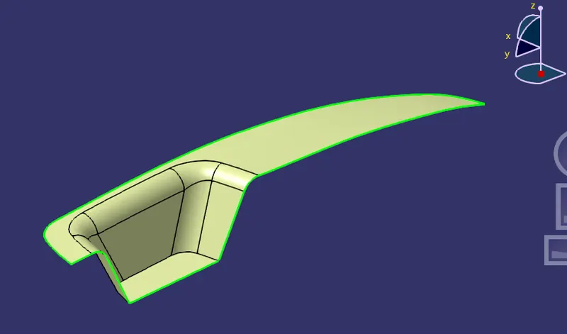
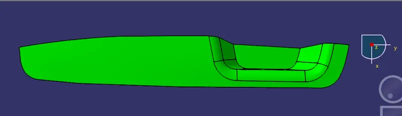
- The above image shows the Class A surface of Switch Bezel. From the given orientation, it can be made out that extracting the part along Y or X axis is complicated and required side core to form the Cup. Hence by engineering judgement, Z is assumed to be the tooling direction.
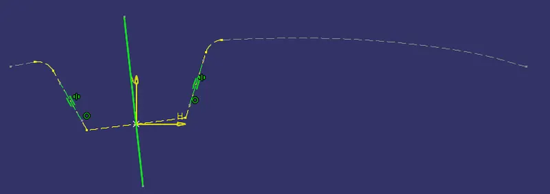
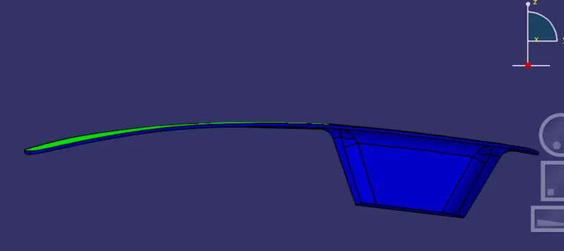
- In the sketch window, intersection command is used to intersect class A surface and Y-Z plane to form surface profile visible to Y direction.
- The two oblique surface lines that are closer to being parallel with the Z axis or tooling axis are problematic for draft clearance. Hence a line is created bisecting those oblique profile lines. This line clears the Y direction for tooling.
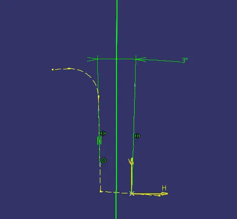
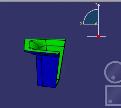
- Similarly, the previous procedure is followed to Z-X profile of the component. This line clears the tooling for X-direction.
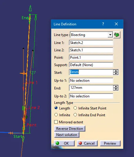
- Both the axes clearing the X and Y directions are selected to create Main tooling axis using Bisect option in Line command.
Performing Draft Analysis:
- Feature draft analysis is used to perform draft analysis for the Switch Bezel.
- First, compass is selected under direction panel to align the compass with the tooling axis.
- Once the compass is set, it is locked in the position and class A surface is selected.
- The colour scale is turned on and 3 degrees is set as the upper limit. Henceforth, the surface are coloured according to the draft angle.
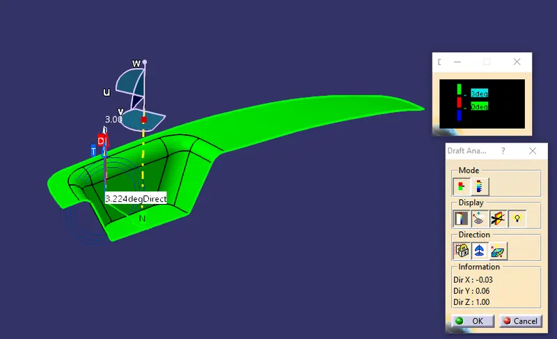
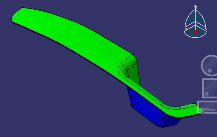
As the image displays, all the surfaces are green, indicating that all surfaces have draft angle equal or greater than 3 degrees. This concludes that the component can be easily extracted from the moulding machine.
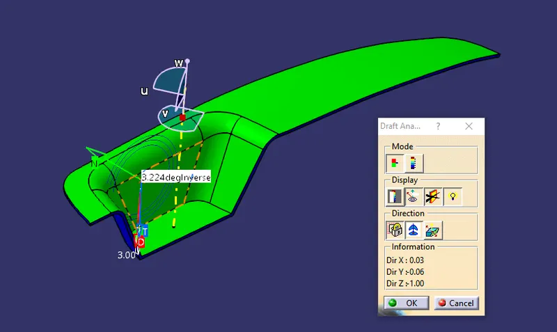
The above image is the draft analysis for final solid component.