Project - 2 - Meshing on the suspension Assembly
Aim:
To check for geometrical errors and obtain clean topology for the Rear Suspension model. To identify shell and solid components and components with uniform and non-uniform thickness and mesh them with appropriate meshing techniques and considering the quality criteria. To deploy the connections between various components and mirror the model to obtain the whole rear suspension assembly.
The quality criteria for Tyre and rim:
|
S.No |
Quality Criteria |
Value |
|
1 |
Target/Average length |
6.5 |
|
2 |
Minimum Length |
5 |
|
3 |
Maximum Length |
10 |
|
4 |
Skewness |
45 |
The quality criteria for non-uniform thickness entities:
|
S.No |
Quality Criteria |
Value |
|
1 |
Target/Average length |
4 |
|
2 |
Minimum Length |
2 |
|
3 |
Maximum Length |
6 |
|
4 |
Skewness |
45 |
The quality criteria for uniform thickness entities:
|
S.No |
Quality Criteria |
Value |
|
1 |
Target/Average length |
4 |
|
2 |
Minimum Length |
2 |
|
3 |
Maximum Length |
6 |
|
4 |
Aspect |
3 |
|
5 |
Warpage |
15 |
|
6 |
Skewness |
45 |
|
7 |
Jacobian |
0.7 |
|
8 |
Minimum Quad Angle |
45 |
|
9 |
Maximum Quad Angle |
135 |
|
10 |
Minimum Tria Angle |
30 |
|
11 |
Maximum Tria Angle |
120 |
And for volume mesh, Tetra collapse of 0.2 mm.
Procedure:
- Geometry clean-up:
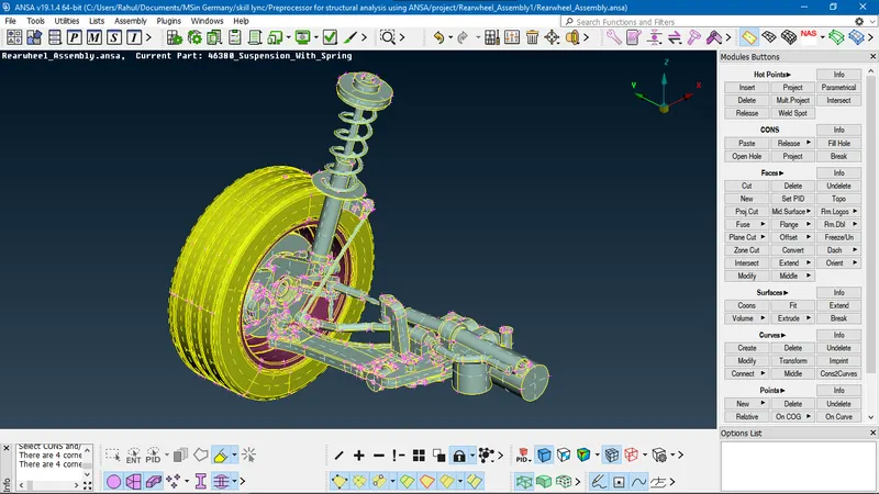
- The image shows the isometric view of the rear suspension model. It consists of Tyre, Rim and suspension assembly and disc brake assembly.
- The geometry of the given CAD model is checked using Tools > Checks > Geometry function. The check is performed on the entities visible on the screen as shown below:
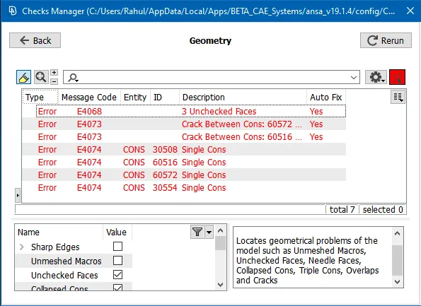
- At the bottom of Checks manager window, Template is visible. Template defines the list of errors that manager needs to look for.
- All the errors found in the model are displayed on execution of the Checks manager.
- The unchecked faces are the deformed faces. These faces are deleted using TOPO > Faces > Delete function and new face is created using Faces > New.
- Single cons are the surface perimeters when adjacent surfaces are not linked. The surfaces are connected in ANSA using Faces > Topo or Cons > Paste option.
- Meshing the Tyre:
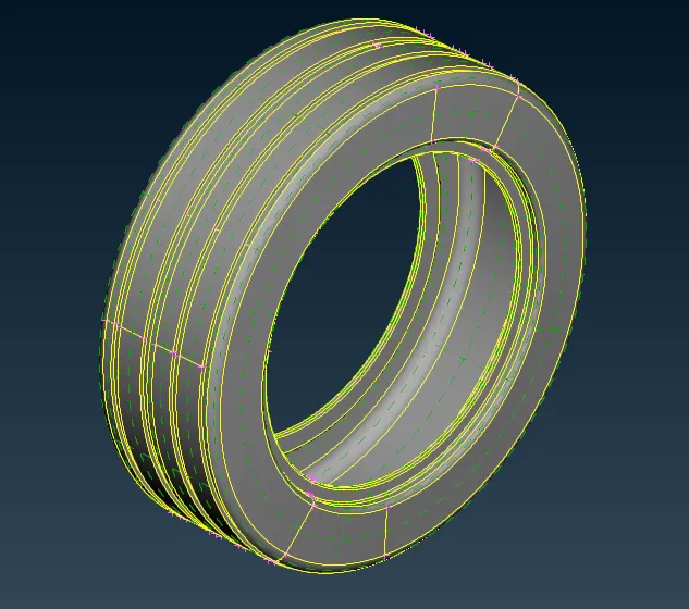
- Tyre part is isolated on the screen using Focus > Or with Part selection tool
- The quality parameters are set in Utilities > Quality Criteria and Mesh parameters as shown below:
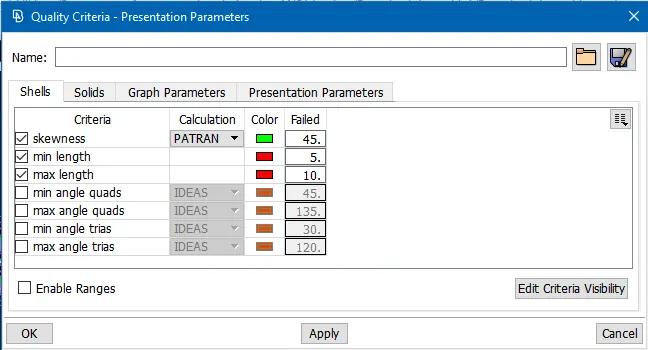
- The parameters demand the finite elements to have side length in the range of 5 to 10 mm
- Skewness is the difference of 90 and the minimum internal angle of a trial element.
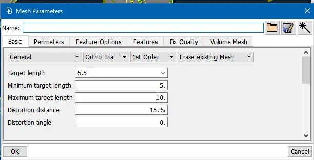
- The ideal element finite element size is set to 6.5 mm.
- The element type is set to ortho tria since tyre is supposed to be 3D tetra meshed.
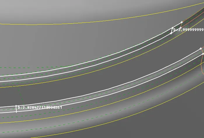
- Measurement is done using Utilities > Measurement to check for the distance between the feature lines. Since the minimum element length is 5 mm, 5 mm should be the minimum distance between the feature lines. As shown above, some fillet regions are having a distance of less than 5 mm. These fille areas as defeatured by suppressing the double cons. Suppression of cons is done using TOPO > Faces > Cut (right-click). This works as Join.
- The length between the hot points or nodes on the Perimeters and Macros is changed to target element length of 6.5 mm using MESH > Perimeters > Length.
- The batch Meshing Technique is used. Batch Mesh is available in Tools in Menu bar. Batch Mesh is an efficient tool to produce mesh automatically. Before using this tool, a new part model is created for the Tyre :
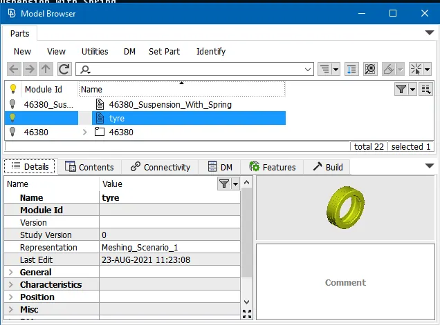
- In the model browser window, Set Part option is activated and tyre is selected from the screen. On middle-click, Tyre part is created as shown.
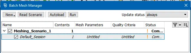
-
- The above window appears on activating Batch Mesh. A new meshing scenario is created by pressing New button
- The parts to be meshed is defined by double-clicking on the Contents column. Contents of Meshing scenario window appears. Here, the tyre model is selected from available list and green arrow is pressed for selection
- The Mesh Parameters and Quality criteria are taken as previously defined.
- The Run button is activated to generate the mesh
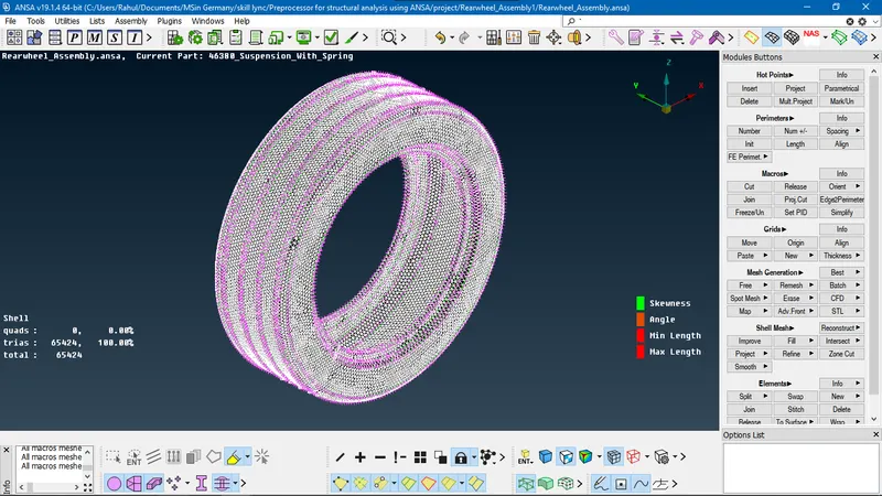
- The whole component is meshed using tria elements and no Off elements are generated.
- Before meshing the volume of this component, quality criteria for Solid is set using Utilities > Quality Criteria function.
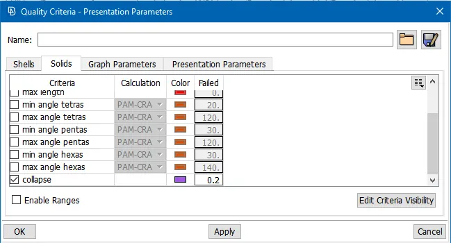
- Collapse criteria is enabled under Solids tab and 0.2 is assigned as failing criteria.
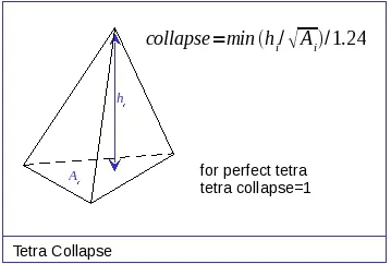
- Collapse determines the idealness of the shape of tetra element. Collapse is 1 for perfect tetra.
- The tetra mesh or volume mesh is generated for this component by defining the volume. Volume is defined using VOLUME MESH > Volumes > Define (Manual). Then the whole tyre component is selected and on confirmation, ANSA prompts the user to select the property for the new closed volume.
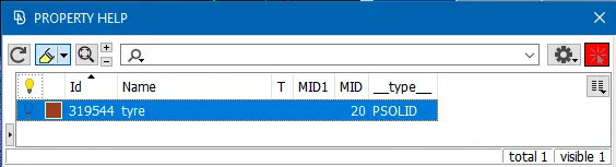
- PSOLID ID is created in the Property Help window using right-click > New as shown below:
- The new volume is then available in Volumes > List as seen below:
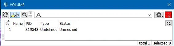
- The type of volume mesh is not defined and the volume remains unmeshed. To generate volume mesh, Remesh option is selected by right-clicking on the volume PID. Then the window appears with the list of different volume mesh algorithms. Tetra FEM method is selected from the list and confirmed.
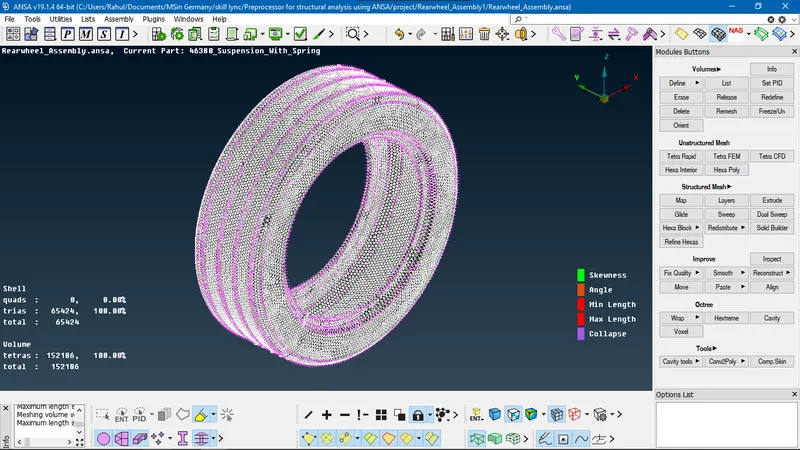
- The volume mesh is generated without collapse failures as indicated on the bottom left corner.
- Meshing the Rim:
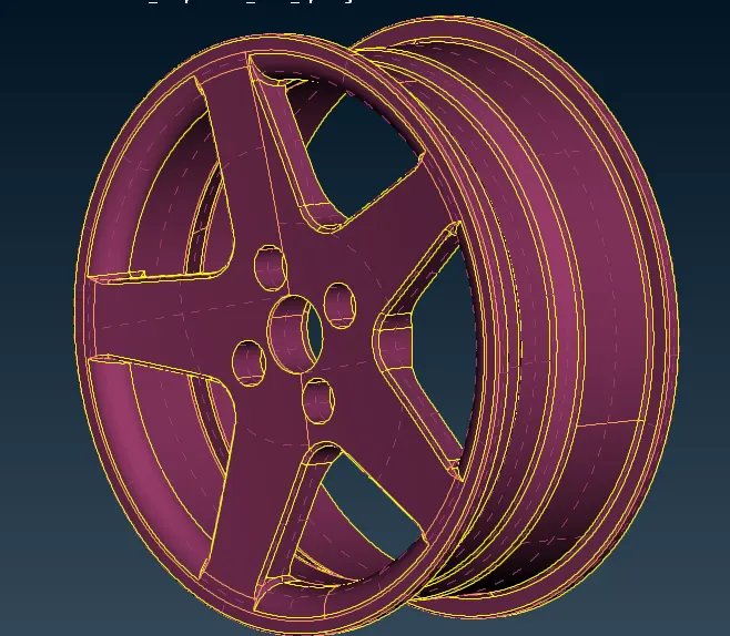
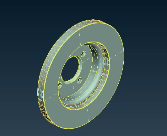
- The image shows the rim. It is a non-uniform thickness component that is meshed with same quality parameters as the tyre.
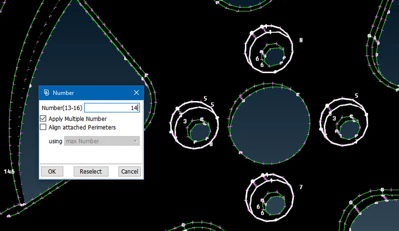
- The bolt holes on the rim are prepared for meshing by equalizing the hot points on the hole perimeter using MESH > Perimeters > Number. All the cons representing the bolt holes are selected and 14 is assigned. This function alters the hot points on all selected perimeters to be 14. This is done since this results in good mesh flow.
- The same batch meshing technique and volume meshing technique is used for Rim as Tyre.
- Meshing the other non-uniform thickness components:
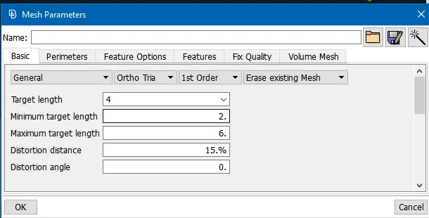
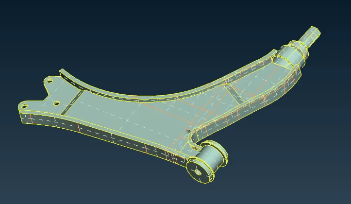
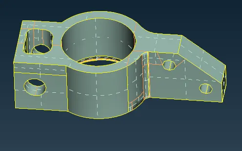
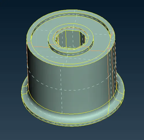
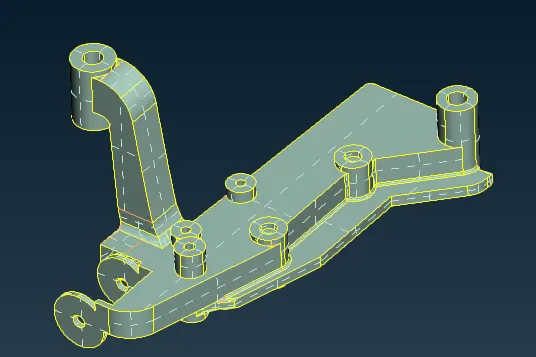
- The meshing parameters and quality criteria are set for non-uniform components as follows:
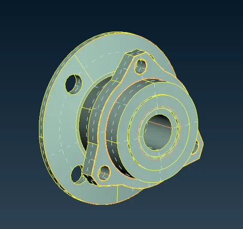
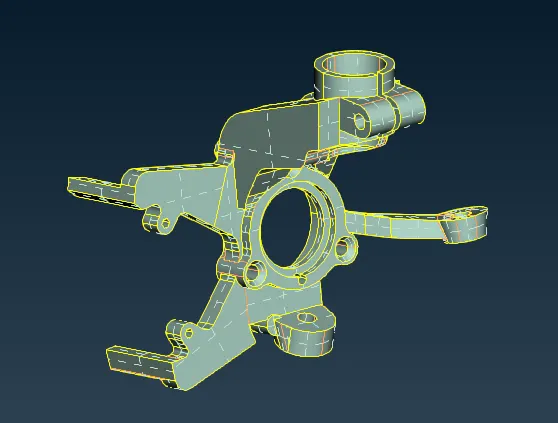
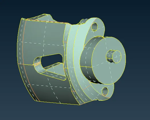
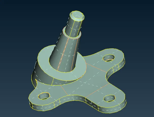
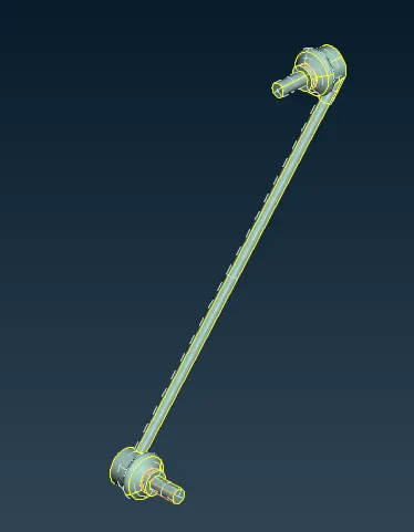
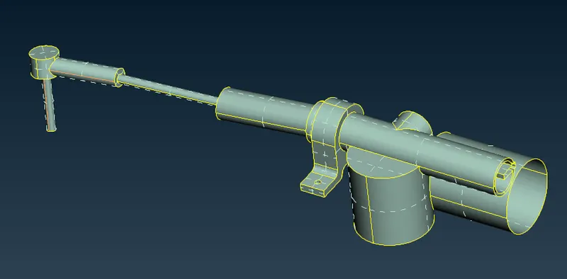
- The components to be meshed are isolated on the screen using Focus > Or using Part selection tool. The following parts are selected:
- All these components are meshed using MESH > Mesh Generation > Batch function.Batch generates automatic mesh. Batch function also defeatures the CAD surface if the feature lines lie close to each other such that the minimum length is breached.
- In the options list, element type is selected as ortho tria for curved surfaces and as Tria for plane surfaces. Then the mesh is generated on selected micro areas.
- If any quality failures occur, they are resolved using Shell Mesh > Reconstruct function by setting the appropriate element type in Option
- Closed volume is defined for the components using VOLUME MESH > Volumes > Define function. The component to be volume meshed is selected manually and previously created Solid property is selected.
- This volume then appears in the Volumes > List. The status of this volume appears unmeshed. The volume mesh is generated by right-clicking on the volume and selecting Remesh. The window appears with different meshing algorithms. Tetra FEM method is selected and 3D mesh is created.
- The quality issues encountered in the mesh are as follows:
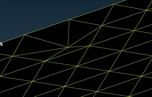
- These surface deformations are called kinks. A kink is formed when the surface is deflected inwards and raised edges are formed when the surface elements are deflected outwards. Both the deformations are unacceptable.
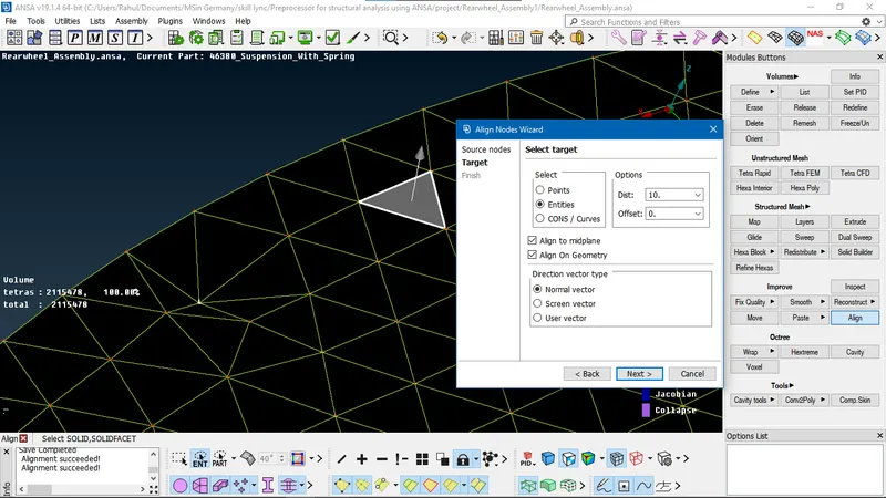
- The kink or raised edge can be resolved using Align function in VOLUME MESH > Improve. Then source node is selected: the node that is deviated from the surface plane. Then target is selected, the point or entity up to which the source node is supposed to move. Target is any entity on the surface plane. Then the source node automatically aligns itself to the target entity.
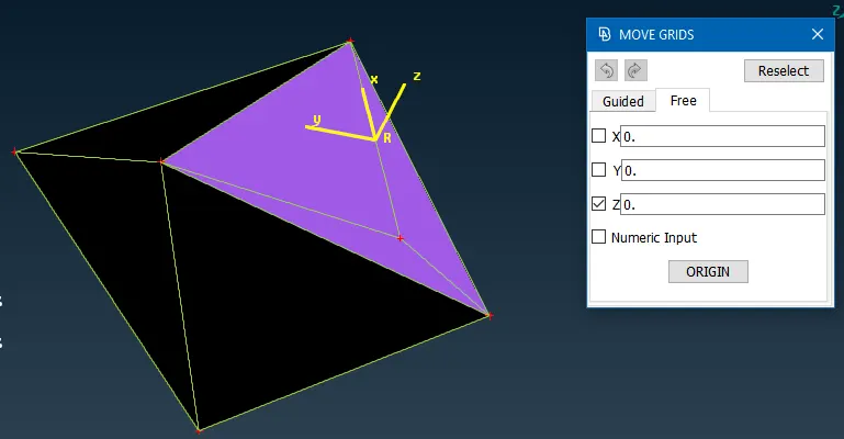
- The issue shown in the image is tetra collapse. Tet collapse is the tetra element of unacceptable size. This occurs when the height of tetra element is too low.
- This issue is resolved using VOLUME MESH > Improve > Move.
- Move function moves the grids. In the Move Grids window, Free tab is chosen. Free tab allows the user to set local coordinate system by a right-click. The X and Y directions would not increase the height of tetra element, only Z-axis is enabled and the node is moved freely using cursor. This way, height of the element is improved and collapse failure is resolved.
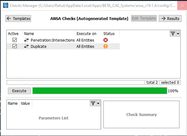
- These errors are encountered when the closed volume is defined for a component. These errors are made visible on screen by right-clicking> show only.
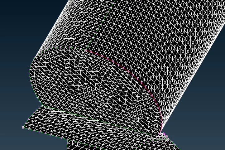
- A free edge is found on the surface. This corrupts the closed volume and caused Penetration error. The free edge is represented by the single con (red line). It indicates that the surfaces are not stitched together.
- The error is resolved by performing Topo on the component in TOPO > Faces. This function stitches the surfaces together and eliminates the free edges in closed volumes.
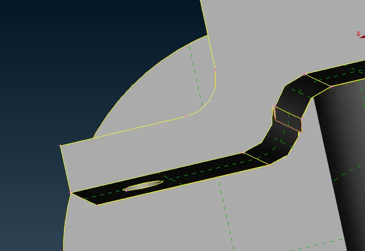
- The unnecessary surface entity in this image creates Duplicate error.
- This error is resolved by deleting the redundant face using Faces > Delete function in TOPO deck
- The meshing parameters and quality criteria are set for non-uniform components as follows:
- Meshing the uniform thickness component:
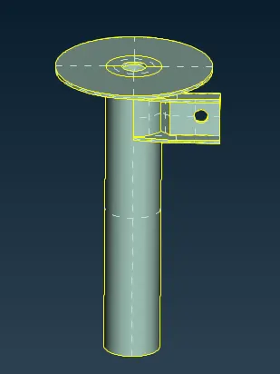
- These are two separate uniform thickness components of thickness 3 mm. These components are supposed to be 2D meshed.
- Mid surface is created for these components separately using TOPO > Faces > Mid. Surface (Skin) function.
- Then a face is selected from the component. The function automatically identifies the Inner side, outer side and thickness side of the whole part using red, green and blue colours respectively.
- On confirmation, ANSA prompts to select a side that needs to be replicated at the middle. And the mid surface is generated.
- The mid surface is prepared for mesh by setting the node distance on Perimeter and Macros using MESH > Perimeters > Length to 4 mm.
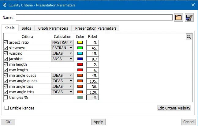
- The quality and mesh parameters are set in Utilities as follows:
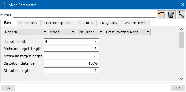
- The finite elements type is set to Mixed. It consists mainly of quads along with trias.
- Then the mid surfaces are meshed using Spot Mesh in MESH > Mesh Generation and all the mid surface macros are selected and confirmed.
- The trias on the free edges and perimeters are avoided using MESH > Elements > Split function
- The opposite trias are eliminated using Split and MESH > Grids > Paste function.
- The quality issues are resolved using Reconstruct function in MESH > Shell Mesh
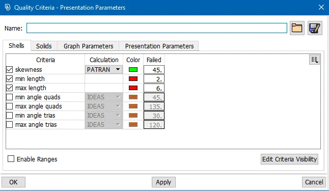
- Then the thickness is enabled for this 2D mesh by enabling Draw Shell as Solid in Quality Criteria > Presentation Parameters.
- 1 D meshing of Spring element:
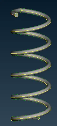
- The image shows coil spring of the suspension assembly. The coil diameter is measured to be 5 mm.
- In order to 1 D mesh the coil spring. 1D representation of the coil is created using curve
- TOPO > Curves > Middle option is used to create a curve running through the coil spring at the center. The double cons on either side of the coil are selected as first and second group of cons selection.
- The curve is segmented into multiple curves. It is made as one using Curves > Connect (Multi) function.
- A 3D point is created to represent the Center of Gravity of the spring using TOPO > Point > On COG (Edges) and selecting the curve
- 1D mesh of the spring is created using NASTRAN > ELEMENTs > CBAR function. This function creates a simple beam element.
- A window appears and picks mode is selected as curve and the spring curve is selected
- On confirmation, ANSA asks for a node for orientation. The spring COG point is selected
- The element length of the 1 D mesh of 4mm is entered in the Input window.
- Then in the Property card, PBAR property is created.
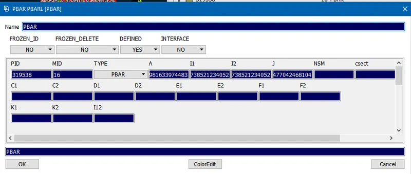
- A is the cross-sectional area of beam element. In that field, shift+? is pressed to calculate the area of cross-section through entering radius of 2.5 mm, since diameter of spring is 5 mm
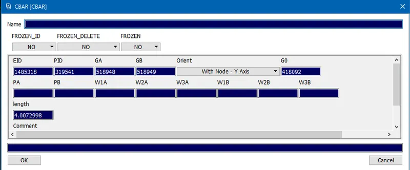
- This is the CBAR card that shows the properties of CBAR elements like element ID, Grid ID
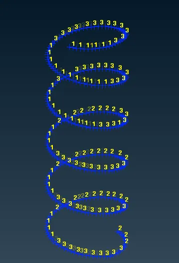
- The image shows the 1D mesh of spring
- Connections are deployed between the various components
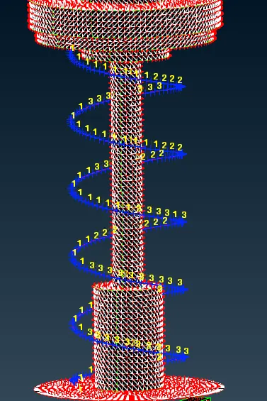
- The figure shows the spring element and adjacent parts. The spring element is connected to the adjacent parts using NASTRAN > ELEMENTs > RBE2 (two nodes). RBE2 stands for rigid body element.
- The end node of CBAR element and a node on the adjacent part FE is selected
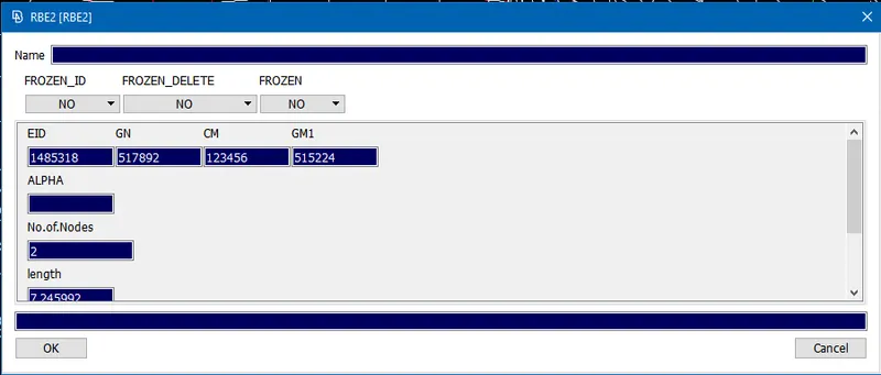
- The following RBE2 window appears and shows vital information of this connection like GN :Master node ID, GM1: Slave node ID and CM is the locked degrees of freedom wherein 1, 2, 3 are translational motion along X, Y, Z axes and 4, 5, 6 are rotational motion about X, Y, Z axes respectively.
- The Rigid body element connection is realized as shown below by a yellow line.
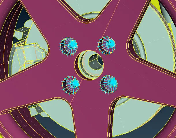
- The connecting parts are Rim and Disc brake assemble. Both the parts are connected through concentric bolt holes using RBE2 (Many nodes) function.
- The edges of the holes are selected using Loop selection tool as slave nodes. On selection, master node is automatically created at the geometric center of all slave nodes.
- All the slave nodes have dependent degrees of freedom and master node has independent degrees of freedom.
- The RBE2 window displays the info about the connection. In the CM field, all the numbers associated with degrees of freedom are assigned since bolt is complete rigid connection.
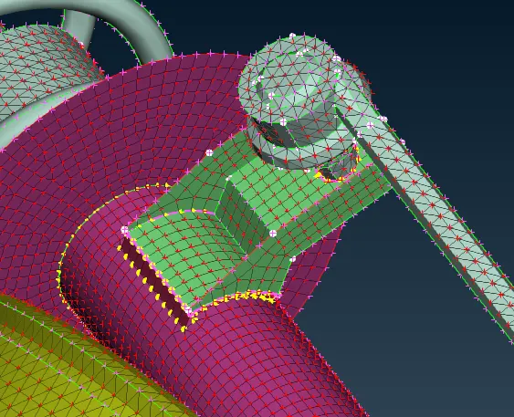
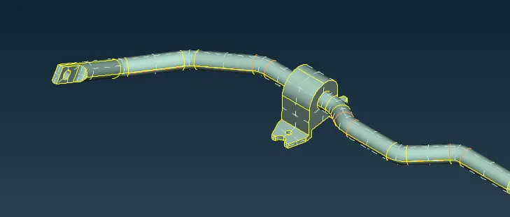
- The image shows the parts connected using seam weld. The central part is connected to the base cylinder (parallel surfaces) and to the rod (perpendicular connection).
- The free edge and the hole perimeter of the mid surface of central part is selected and converted to cons using TOPO > Curves > Cons2curves function
- The curves are converted to seam lines using Assembly > Convert (Seamline connection type)
- The connection is realized using Connection manager in Assembly. One of the seam lines is selected and the following window appears:
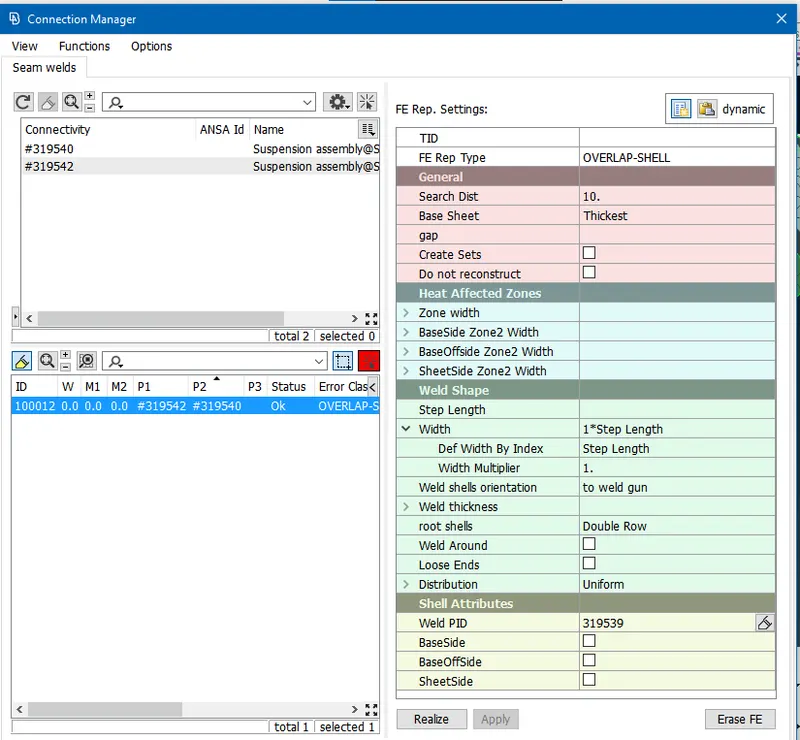
- On the left side, P1 and P2 represent the parts to be connected. The respective property ID is entered in the field.
- FE representation type is set to OVERLAP-SHELL for parallel faces
- Seam weld PID is created in Property card and selected
- The step length is the element size for weld FE. It is derived from the selected parts when left blank.
- Finally, Realize button is clicked to materialize the connection.
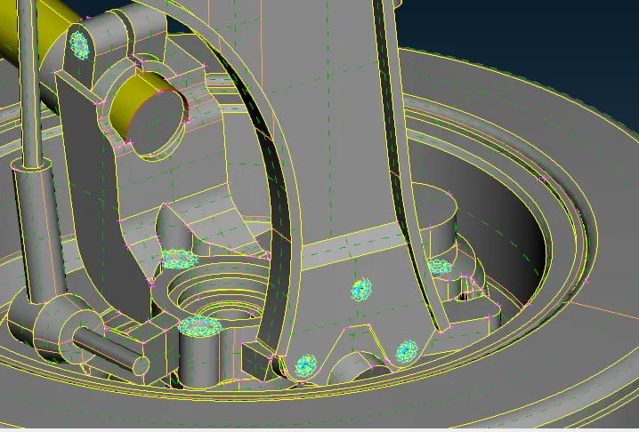
- The image shows the rest of the bolt connections deployed using RBE2 (Many nodes)
- Completing the rear wheel assembly by mirroring left half assemble to the right
-
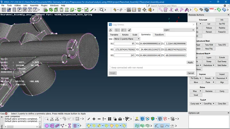
- Since meshing and connections for the half rear wheel assembly is complete, it is replicated to the right side using Utilities > Transform function
- In the transform window, symmetry tab is selected and the mirror operation is executed using Mirror 3 points plane
- The 3 points plane is created by selected 3 points on the part on the same plane as shown above.
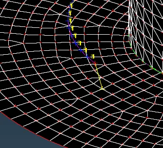
- On applying the setting, Transformation option window appears. The PID is set to the same.
-

Conclusion:
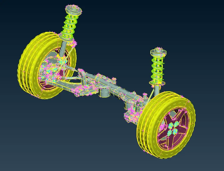
The image shows the transformed part using mirror plane. All the entities like 1D elements, 2D mesh elements, 3D mesh elements along with CAD and connections are replicated and reproduced to the right side.
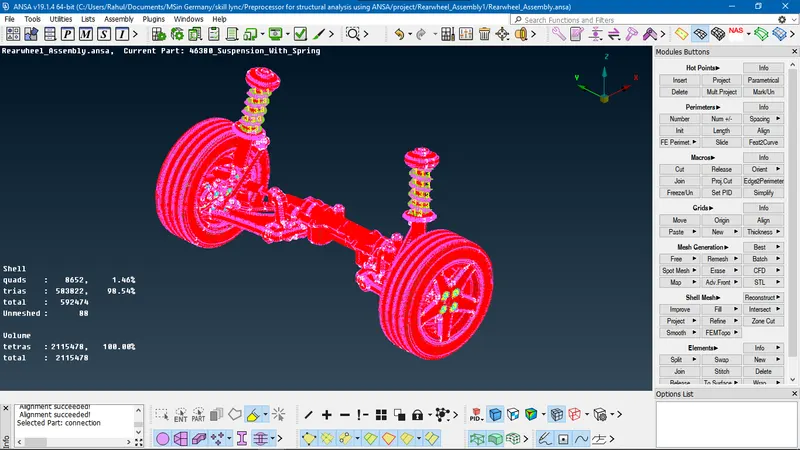
The image shows the finite elements information on the left side like the number of quads and trias in Shell mesh and number of tetras in volume mesh. There are few quality failures for shell mesh and none for solid mesh. All the tetra collapse issues are resolved but errors regarding skewness, minimum length and maximum length remain.
Learning outcomes:
- MESH > Mesh Generation > Batch is a useful tool to create mesh quickly. This tool automatically defeatures if the feature lines violate the quality parameters. Manual defeaturing consumes a lot of time.
- Deformed FE surface is improved using Align tool. This function can be used to level the FE
- Seam weld using Overlap shell or Y-joint shell FE representation fails if the seamline is not a single con. If seam weld needs to be deployed at double cons, then the FE is released using MESH > Elements > Release function, then seam weld is deployed since in FE all perimeters are single cons. Later on, the FE is stitched using Paste function.
- The ortho trias failing for maximum length criteria can be resolved by increasing the number of hot points on the perimeter using MESH > Perimeters > Num+/- function.