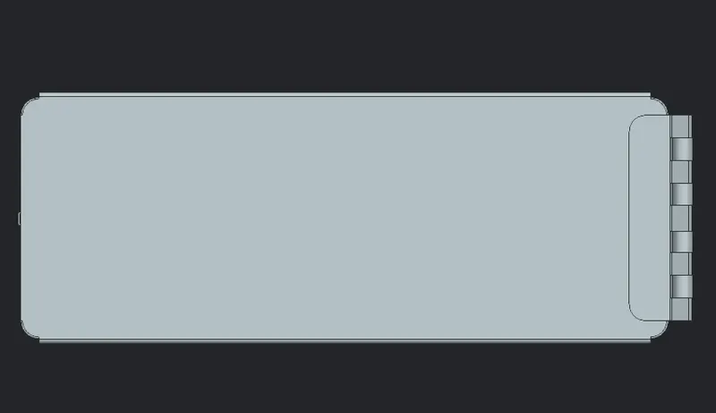
Advanced Sheet Metal Design Using NX Cad Challenge_2_Box Assembly
Title:
Design of the Sheet Metal Box Assembly using Siemens NX
Objective:
- To layout the procedure to form the Box Assembly
- To follow the procedure and use appropriate features and commands to accurately model the part in Siemens NX
- To capture and attach various standard views of the final model
Introduction:
Sheet metal box assembly consists of base, sidewalls, lid and two hinges connecting top lid with the side face for opening and closing of the lid. The box also has features on the side walls and base. Sheet metal is a single flat metal which is bent and using punch and die tools to form various features and give the required size and shape to the sheet.
Design Approach:

Description:
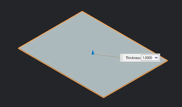
- Tab:
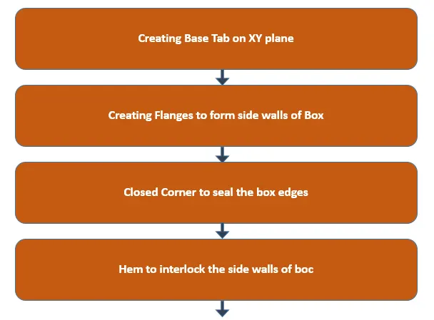
- Tab is the base feature of the sheet metal upon which other features like flange, hem, bend are created
- The tab is created with a thickness 1 mm for a rectangular sketch profile.
-
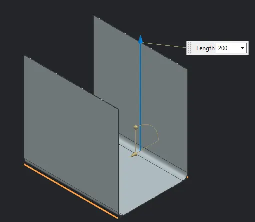
- Flange
- Flange is created on either side of the tab by selecting the edges in which direction flange needs to be created.
- Flange of length 200 mm is created perpendicular to base.
- Length reference is set to Inside. This means that the given length includes the web as well as the bend radius.
- Inset is set to Material Inside. This means that the whole flange is created within the selected edge.
- Bend radius is set to 10 mm
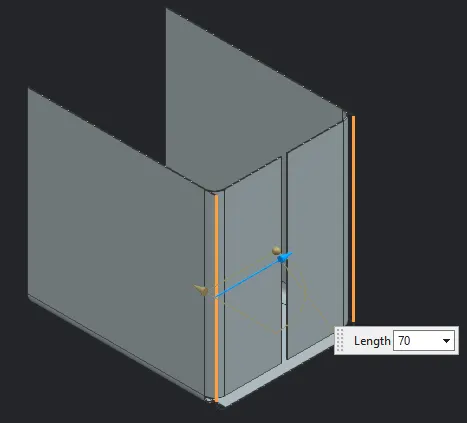
- Flange
- The flanges are created perpendicular to previously created flanges with the same thickness and bend radius and of length 70 mm
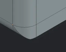
- Closed Corner
- Close and Relief type of corner is created to close the corner regions which are previously open. Both the adjacent bend regions are selected for closing.
- The corner treatment is set to Close and gap is set to 0 so that the corners are completely sealed.
- Overlap is set to none, so no side of sheet metal is extending over other side.
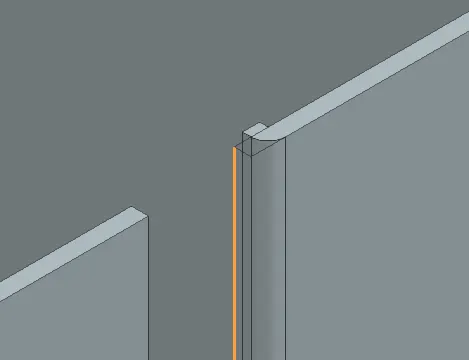
- Flange
- Flange is created normal to the previous flange of length 0.509 mm which includes web length and inner bend radius
- The bend radius is set to 0
- The offset is set to 1 mm by default. This means that flange is created 1 mm away from the selected edge in inward direction.
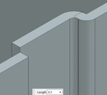
- Flange
- A flange is created normal to the previous flange of length 6.5 mm including inner bend radius and web length
- Bend radius is 0.5 mm and offset is set to 1 mm.
- Hem
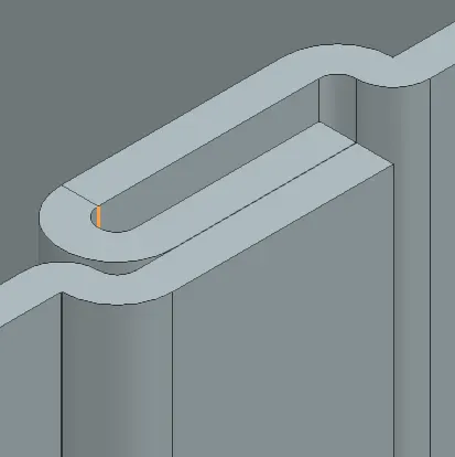
- Hem is created to fold an edge onto itself for safe handling or to increase the stiffness of the sheet metal
- The hem type is set to open, so the folded part is not touching the previous flange
- The bend radius is set to 0.505 mm and flange length is set to 5 mm (Web)
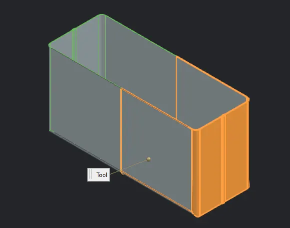
- Mirror:
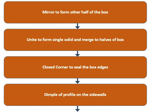
- The half box is mirrored across the YZ plane

- Unite
- Both the half parts are united to create a single body
- Dimple
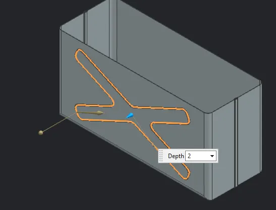
- Sketch is created on the side face of the box and selected for dimple
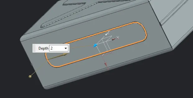
- Dimple elevates the portion of the sheet metal that is enclosed by the sketch profile. The depth is set to 2 mm, hence the profile is elevated by 2 mm.
- The side wall angle is set to 0 degrees, and side walls are created outside the material.
- Other settings like punch and die radius is set to 1 mm.
- Mirror
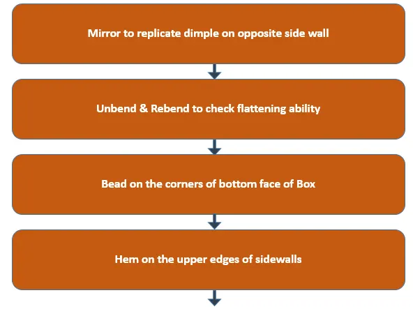
- The dimple is mirrored across ZX plane to replicate it on opposite face of the box
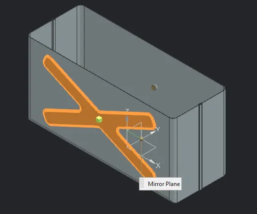
- Dimple
- The elevation of the dimple is 2 mm
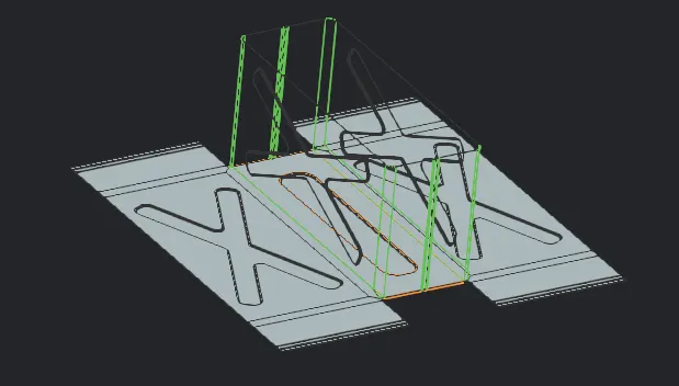
- Unbend
- This command is used to unbend the sheet metal. The base face is selected as stationary face and all the bend regions are selected to unbend.
- This gives flat sheet metal. This command is executed to check if the sheet metal can be flattened
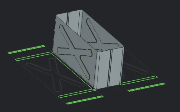
- Rebend
- This command rebends the sheet metal to original form.
- All the bend regions are selected to reform it
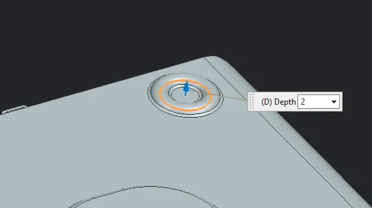
- Bead
- Bead commd creates an elevation on the sheet metal along the sketch profile and not the area enclosed by the sketch profile like in Dimple.
- The elevation is 2 mm above the base and radius of curvature of the elevated bend is also 2 mm.
- The die radius is set to 1 mm
- Mirror
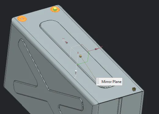
- The bead is mirrored across the ZX plane first and then both the beads are mirrored across the YZ plane to have four beads at four corners of the Tab
- Hem
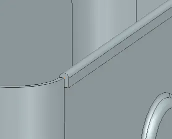
- The sides of the box are hemmed outside.
- The hem bend begins on the outside of the edge by setting Inset option to bend outside.
- The length of the flange is 2 mm
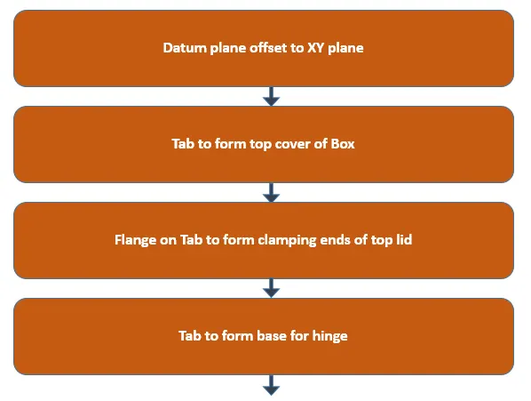
- Datum plane
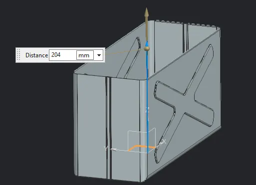
- New plane is created by offsetting XY plane by 204 mm
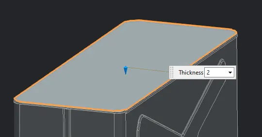
- Tab
- Base Tab is created to create the top cover of the box of thickness 2 mm.
- Flange
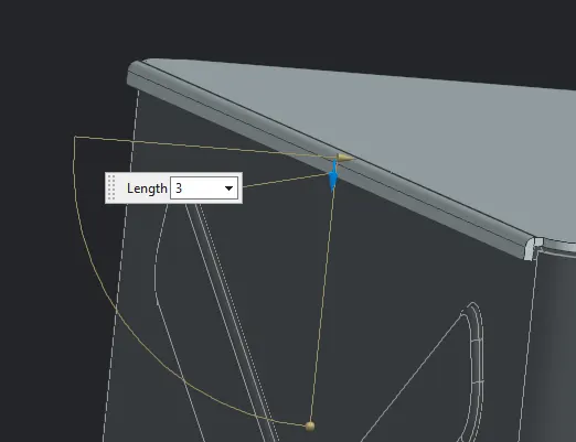
- Flange is created on the edges of second tab in the direction normal to tab
- The length of the web of flange is set to 3 mm; Bend radius is 0.5 mm
- The flange bend is created outside the selected edge offset by 0.5 mm.
- Tab
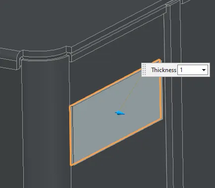
- Base Tab of thickness 1 mm is created to form base for the hinge
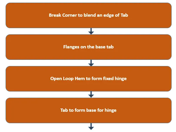
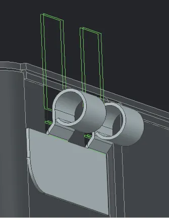
- Break Corner
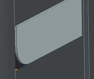
- Break corner feature is used to create corner blend of radius 10 mm.
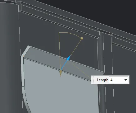
- Flange
- Flange of length 4 mm and inclination of 40 degrees to the base tab is created
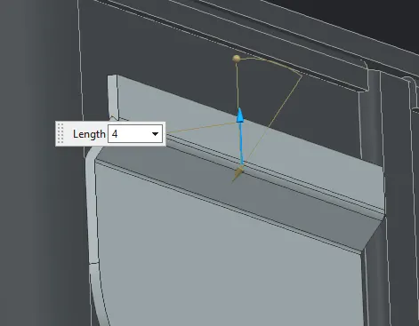
- Flange
- Another flange on the previous flange is created that is inclined 40 degrees to the flange and 4 mm in length
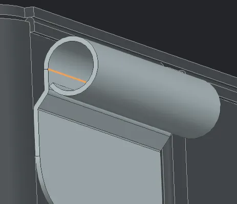
- Hem:
- Hem of open loop type is created
- The loop radius is set to 5 mm and loop rotation is set to 325 degrees.
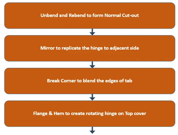
- Unbend
- The base tab is set to stationary face and bend regions of flanges and hem are selected to flatten them out
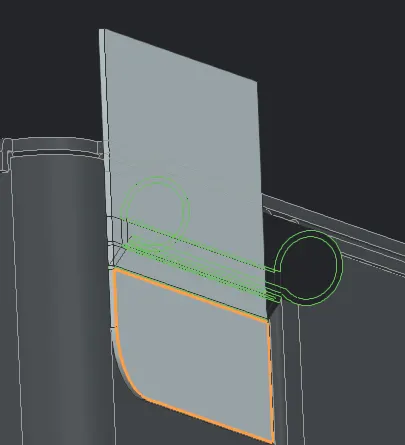
- Normal Cut-out
- Rectangular profiles are sketched on the flattened face and used for normal cut-out
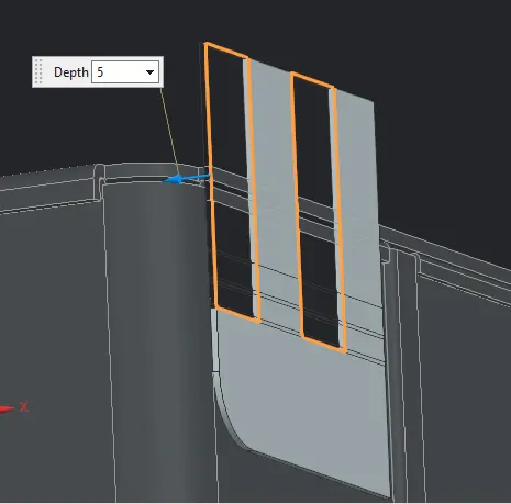
- Rebend
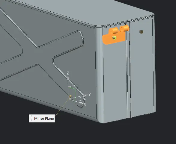
- Mirror
- The stationary hinge is mirrored across ZX plane
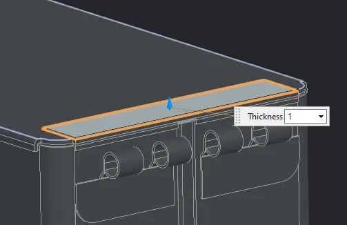
- Tab
- Base Tab of thickness 1 mm. This form the base of the hinge on the top cover
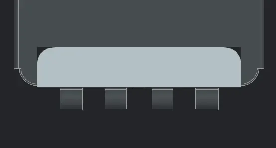
- Break Corners
- The corners are blend with 10 mm radius
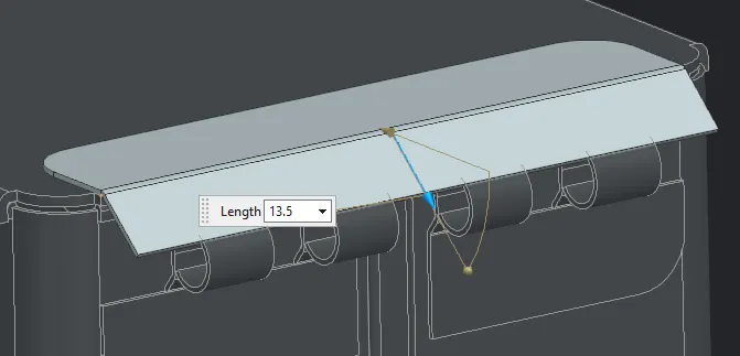
- Flange
- Flange is created on the lower edge of base tab
- Length of the flange is 13.5mm and inclination is 41 degrees to the base tab
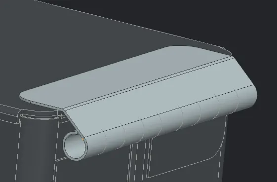
- Hem
- Open loop hem is created with 5 mm bend radius and 325 degree revolved sweep.
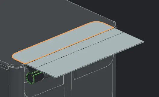
- Unbend
- The flange and hem are unbent to form a flat sheet metal
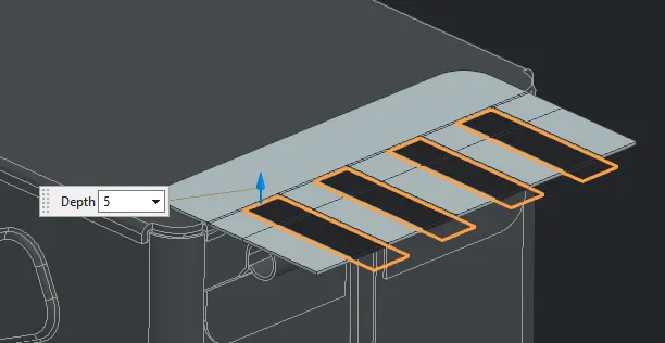
- Normal Cut-out
- The rectangular cut outs are created adjacent to the previously created hinges
- Rebend
- The hinge of the top cover is formed with rebend command

Conclusion:
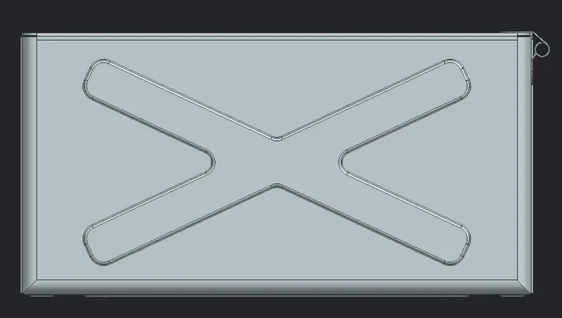
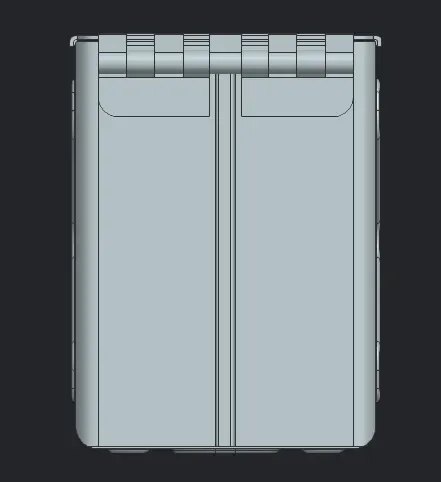
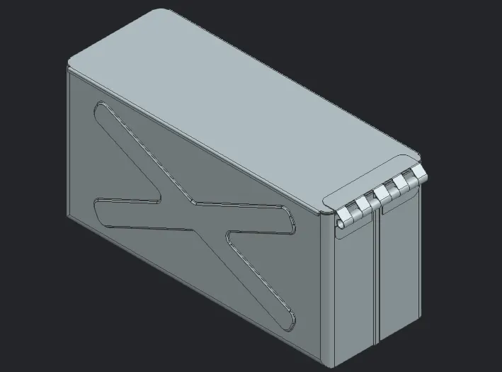
The final model is obtained with good accuracy as shown below:
Front view:
Right View:
Isometric View:
Top View: