Week - 8 - Morphing
Aim: To perform morphing on the components and discuss the industrial application of morphing
Theory:
Morphing is a process of reshaping products.
- In automotive industry, the development time has shortedned from 7 years to 5 years and further shortening. The development cycles are rapid and new cars are launched frequently. This is possible due to rapid design changes made possible by Morphing. A hatchback car is designed as sedan with same design features till C-pillar and beyond C-pillar the features are morphed and extended to form sedan.
- Consumer electronics market has become highly competitive. The design and development cycles for smartphones has reduced to 3 months. Designing a new phone from scratch would take longer lead time and render the company irrelevant in the market. So morphing technique is used to create a slightly different design from existing design.
- The concept of morphing is to get series of designs or shapes that interpolate between two given designs. All these designs are presented to the target customers and study is conducted to determining the most attractive shape
Procedure:
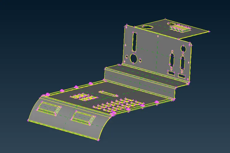
- This is the given sheet metal component. Topo function is run on this component to verify and obtain clean geometry.
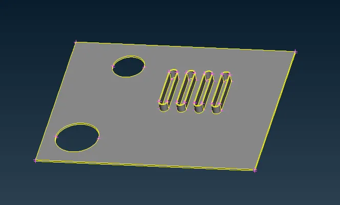
- Using Menu bar > Focus > Or function, this part of the component is isolated
- The elliptical rib features are to be morphed
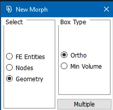
- New morph box is created using MORPH > Boxes > New (ortho) function
- This function creates hexahedral morphing box containing the selected entities and the box is oriented according to the global or local coordinate system.
- In the select panel, Geometry is selected. This lets the user select entities present in the Geometry visibility mode.
- The box type is selected as Ortho. This ensures that the box is oriented as per the global coordinate system
- Then the elliptical rib features are selected and on confirmation, morph box is generated as shown below:
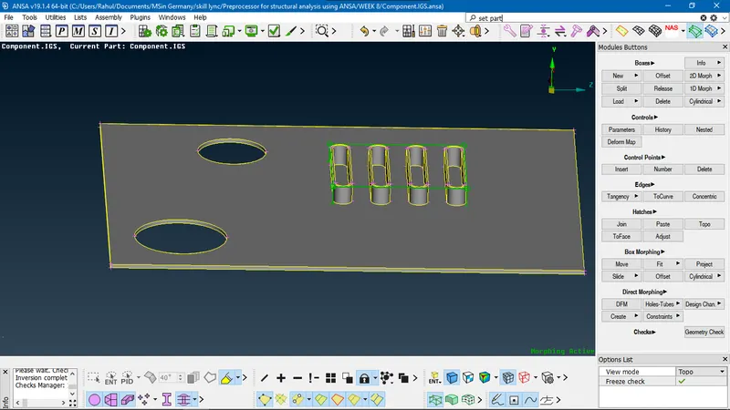
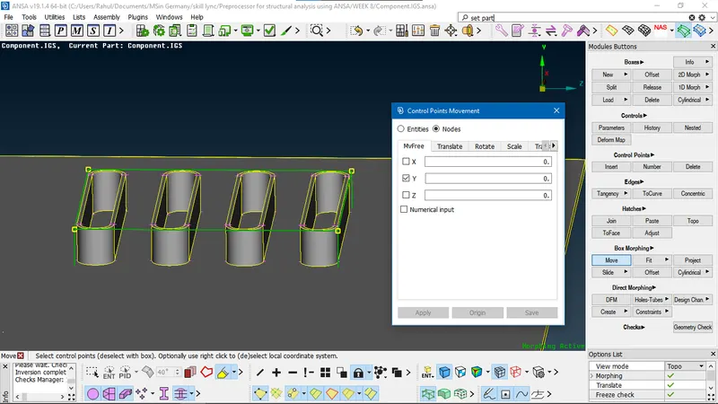
- The size of the rib feature is altered using MORPH > Box Morphing > Move function. This lets the user move the control points or the corners of the box according to the global or local coordinate system and modify the shape of the morph box and the entities that it contains.
- On selection, the Control Points Movement box appears. Nodes option is ticked, this allows the user to select the box node points.
- Since the height of the ribs is required to be altered, the four control points on the top of the box are selected and Y-axis is ticked under MvFree tab as the rib height is oriented along this axis
- On confirmation, ANSA allows the user to change the control point location and in turn the shape of ribs by moving the cursor in the draw area. The movement of cursor along the Y-axis is only accounted for.
- After the change, the shape is fixed by left-clicking and selecting apply on the window. The below-shown dimensions are obtained:
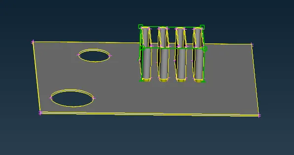
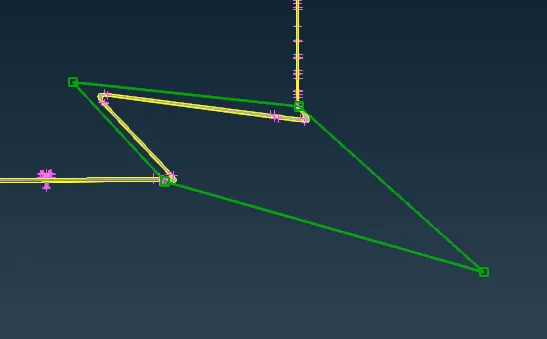
- A new morph box is created for the mid-section of the component containing 2 surfaces and 3 fillets using MORPH > Boxes > New (ortho) function
- The two control points on the top left edge of hexahedral box are selected in Move function
- Under the MvFree tab, all axes are selected and the cursor is moved on the screen to alter the box towards the left and the position is fixed
- Similarly, bottom right edge control points are selected as new nodes for Move function and the cursor is moved towards the right and the position is fixed.
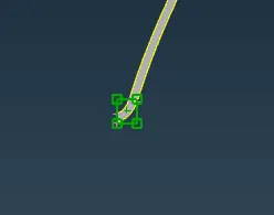
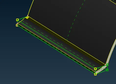
- A new morph box is created for fillet entity at the lower end of the component
- The control points on the left face of hexahedral box are moved further to the left using Move function and fixed as shown below:
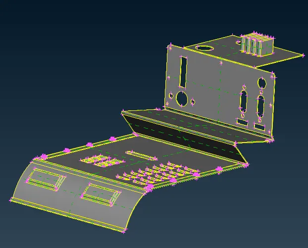
- The final modified component is obtained as shown
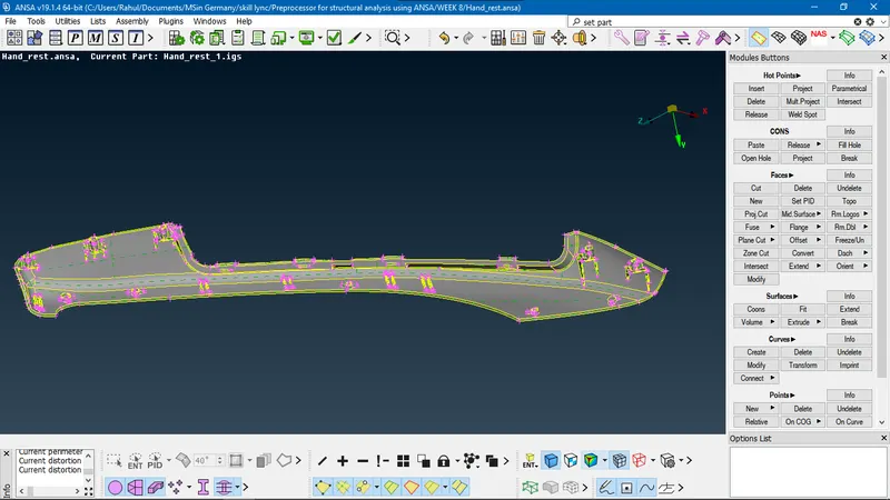
- The new component is loaded into ANSA.
- The dog houses and rib features are identified for morphing. The height of the features are altered using the Morphing technique
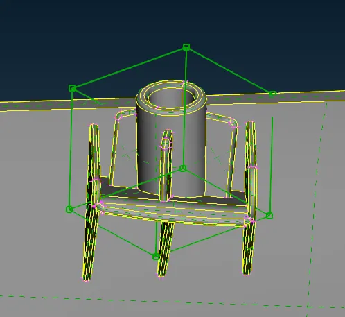
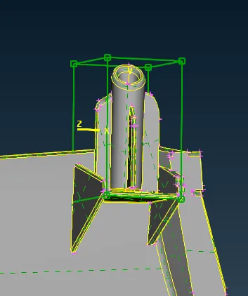
- The dog house feature consisting of cylindrical structure in the middle and ribs supporting around it are captured in hexahedral box using MORPH > Boxes > New function
- Geometry is selected in New morph window and since Ortho is selected in Box Type, the box can be seen as oriented along the global coordinate system. That is, the morph box is oriented in such a way that global axes are normal to its faces.
- It can be seen that the edges of the box are not closest to the selected entity, hence the morph box is of high volume than required.
- When Min Volume is selected as box type in New Morph window, the generated morph box is oriented along the local coordinate system. This morph box is such that it occupies minimum volume as shown below:
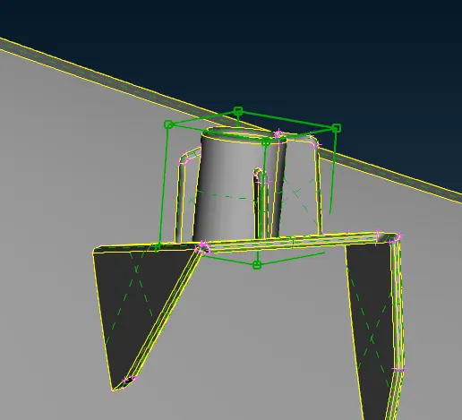
- The morph box is created in such a way that it only envelopes the selected feature and has captured lowest empty space
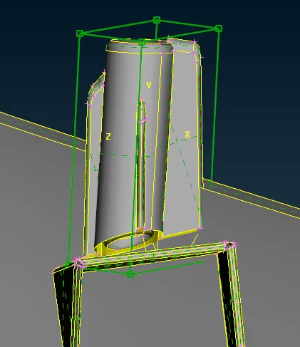
- The height of the dog house and surrounding ribs is increased using MORPH > Box Morphing > Move function
- The local coordinate system represented by a green dot at the center of box is selected with right-click. This way, the axes shown in the Control Points Movement Box are of the local coordinate system
- As it can be seen in the image, the height of the feature is represented by Y-axis and control points on the top face of the box are selected. So Y-axis is ticked in the MvFree tab and cursor is moved upwards to increase the height.
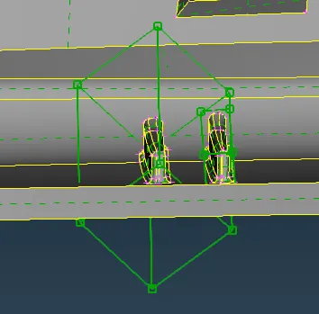
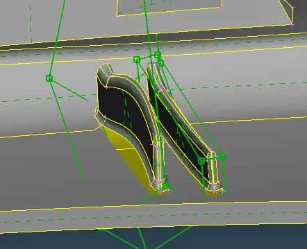
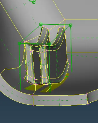
- The following images show the different ways of capturing feature entities in a morph box:
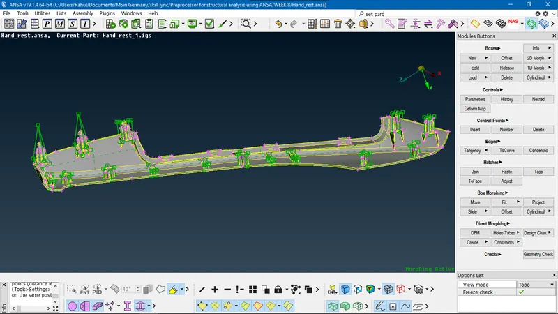
- This shows the final model after morphing the model.