Advanced Sheet Metal Design Using NX Cad Challenge_1_Casing Design
Title of the Project:
Design of Sheetmetal Casing using Siemens NX Sheetmetal Application
Objective:
- To model the sheet metal casing in Siemens NX by using appropriate commands
- To obtain isometric and various orthographic views of the model
- To create the draft of flat pattern of the sheet metal casing and add relevant detailing
Introduction
Siemens NX tool is used to create Sheet Metal Casing in a single part file. Sheet metal application is selected for the part. Before beginning with part modelling, the parameters are set. These are the global parameters, that influence the default values for all the sheet metal features. Primarily, Tab is created. This is a base of the whole sheet metal part upon which other features are added to form the required shape. Then the bends are added. The cut-out features cannot be added while the sheet metal is in bent form, hence Unbend and Rebend features are essential. Beads play a critical role in stiffening the sheet metal. Beads curb the spring-back effect in the sheet metal and prevent it from significantly deviating back to the original position after punch, die or stamping tool is retrieved. Drafting is done after the completion of the modelling of the sheet metal part. Drafting is a process of conversion of 3D model data to 2D engineering data to communicate the manufacturing requirements. The vital feature to implement before drafting is Flat Pattern. This unbends the sheet metal and produces 2D data of the sheet metal.
Design Methodology/Approach:
Description:
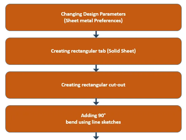
- Sheet Metal Preferences:
- The Global Parameters are changed to 1 mm
- These parameters include Material Thickness, Bend Radius, Relief Depth and Relief Width
- Tab:
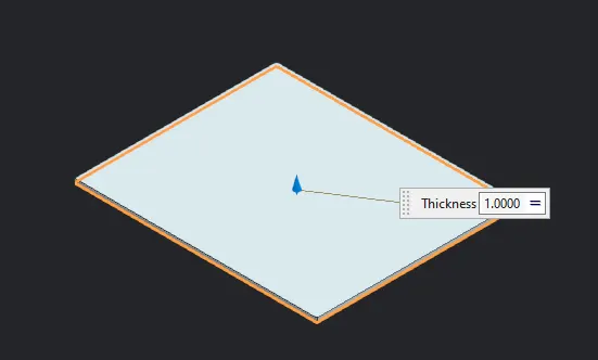
- Tab feature is used to create a base by extruding the sketch along a specified vector for a given thickness value.
- A rectangle of 60 by 50 mm size is made the tab of sheet metal
- The global thickness value is considered by default to create 1 mm thick tab
- Normal Cut-out:
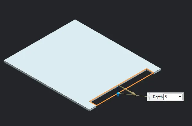
- This feature is used to cut the material from the sheet metal according to the sketch profile.
- Bend:
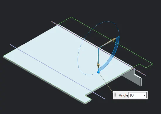
- The bend feature is used to modify the model by bending the material on one side of the sketch
- Straight-line sketches are drawn on the tab face across the body and the tab on either end are bent about the lines
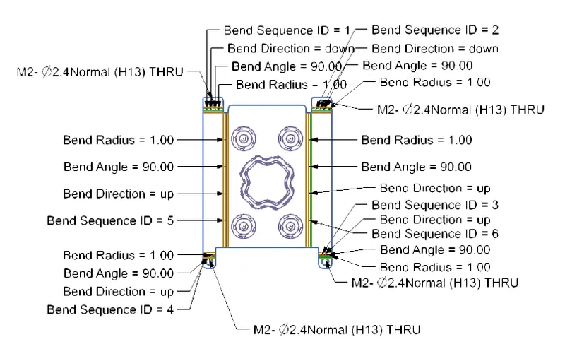
- The bend radius is 1 mm by default and the bend angle is set to 90 degrees
- Flange:
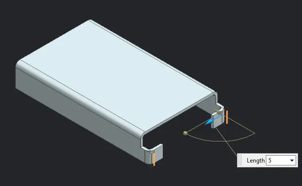
- Flange feature creates a bend region and a web region at the selected base edge
- The length is set to 5 mm, this refers to the size of the web
- The bend angle is set to 90 degrees with default bend radius of 1 mm
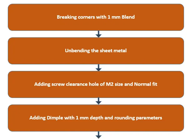
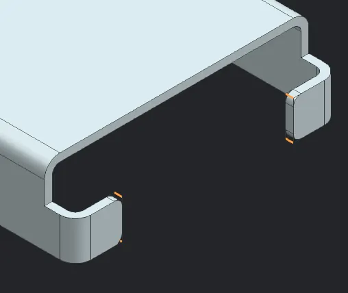
- Break Corners:
- This feature is used to round the sharp corners of the flange and tab
- In the break properties, the break method is set to blend. This creates a fillet of default 1 mm radius.
- Unbend:
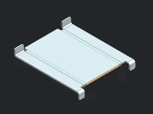
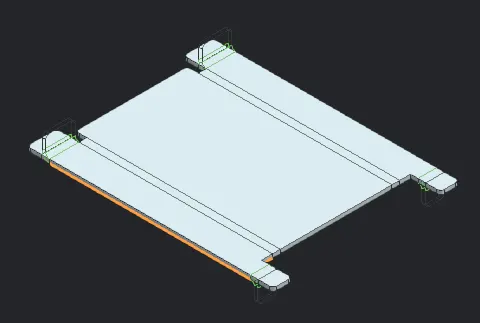
- This command is used to flatten the bend regions usually to create cut-outs
- This is done by selecting a fixed face and selecting the bent regions that are required to be flattened.
- Hole:
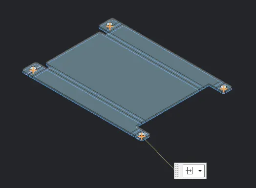
- This command belongs to the modelling application under design features. It is used to create a hole in the part.
- On the tab face, points are created on the flanges and these points are selected for hole creation
- Hole type is set to screw clearance type, size is set to M2 and fit is set to Normal
- Dimple:
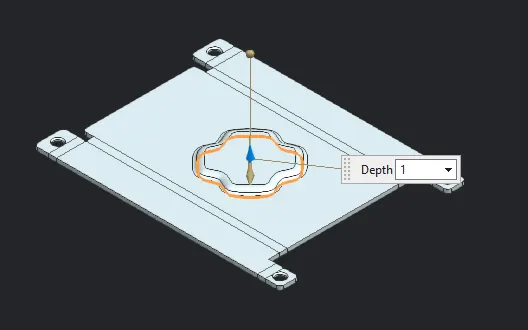
- This command is categorized in Punch. It is used to lift an area of tab to simulate a stamping tool. It creates an indentation on the sheet metal defined by the outline of the sketch.
- A cross sketch is created and spline sketch tool is used to created curved cross. This cross is rotated by 45 degrees using move curves command.
- Dimple command is used to create a dimple of depth and radius 1 mm. Side walls is set to Material inside to create walls of dimple within the sketch outline.
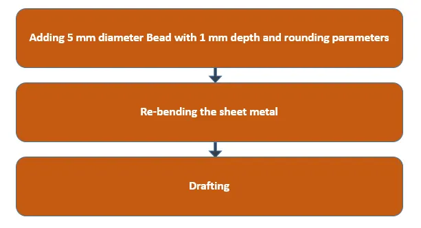
- Bead:
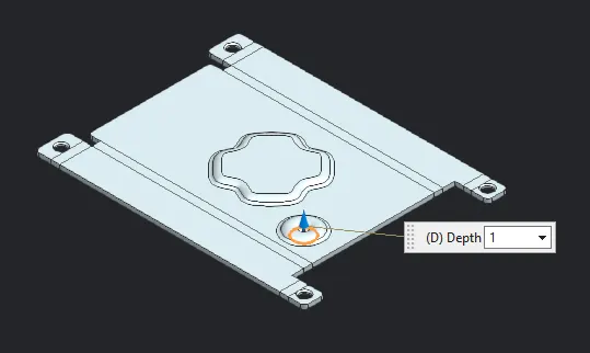
- Bead is a stiffening feature used to create a lift in the sheet metal along the contour of the sketch. It simulates stamping tool.
- Beads of depth and radius 1 mm are created.
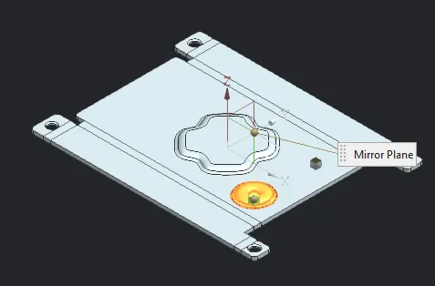
- ZX plane is used as mirror plane to replicate bead on the right side
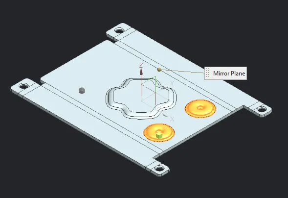
- ZY plane is made mirror plane to replicate both beads on the other side of the Dimple.
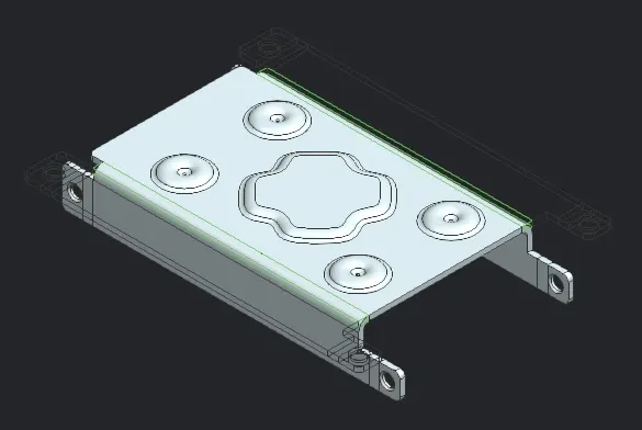
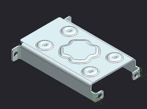
- Rebend:
- Rebend command is used to return an unbend region to its previous bent state. This feature also retains the cut-out features on the bend regions.
- Flat Pattern:
- This command creates a 2D representation of a flattened 3D sheet metal part. The flat pattern is added to the draft.
Conclusion
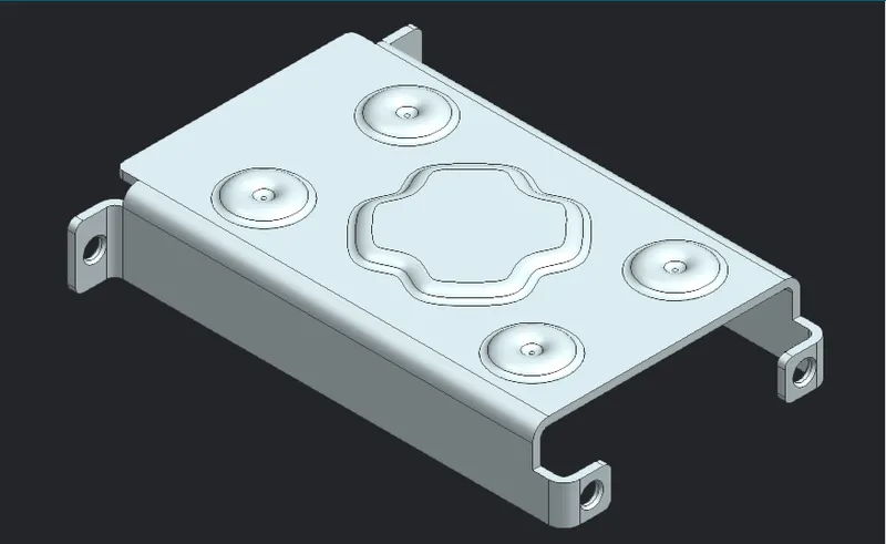
All the features are properly applied to obtain the following 3D part and 2D engineering data:
Isometric view:
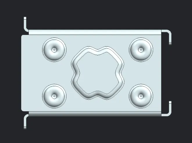
Top View:
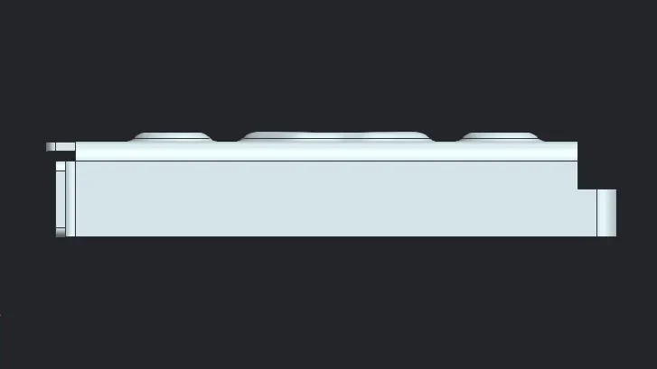
Right View:
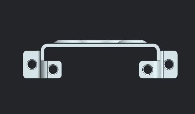
Front View:
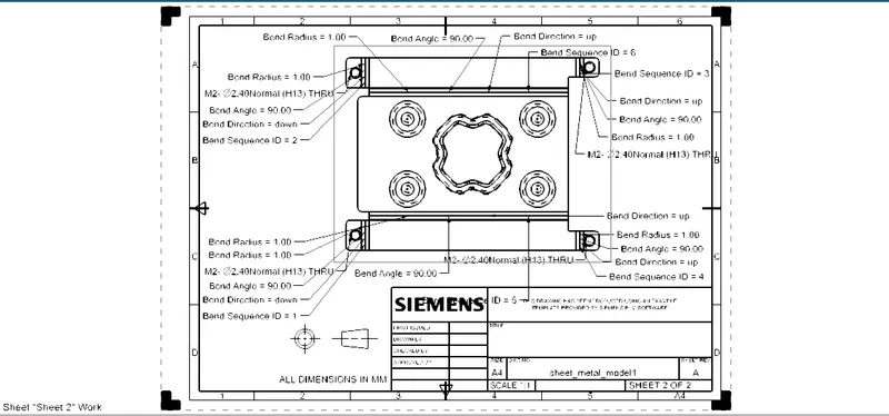
Detailed Drawing Sheet Image: