Week 6 - Creating connection for Rear door
Aim: To deploy suitable connections on the given rear door FE model in ANSA
Procedure:
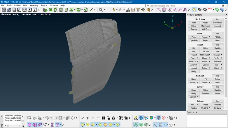
- The image shows the isometric view of the rear door FE model.
- Deploying bolt connections:
- Using RBE2 function
- RBE2 defines a rigid body element of form 2. This element is a rigid body with independent degrees of freedom at a master node and dependent degrees of freedom at slave nodes.
- This function is available in Nastran module (NAS) > ELEMENTs > RBE2
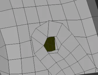
- The holes in the FE model is for the bolt, hence bolt connection is required to be deployed here.
- RBE2 > Many nodes function is selected and the inner perimeters of the shown holes are selected with Loop selection tool. All the nodes on the hole edges are highlighted
- On the middle-mouse confirmation, RBE2 many nodes window appears. All the manually selected nodes are taken as slave nodes.
- The function automatically creates a master node at the centroid by default
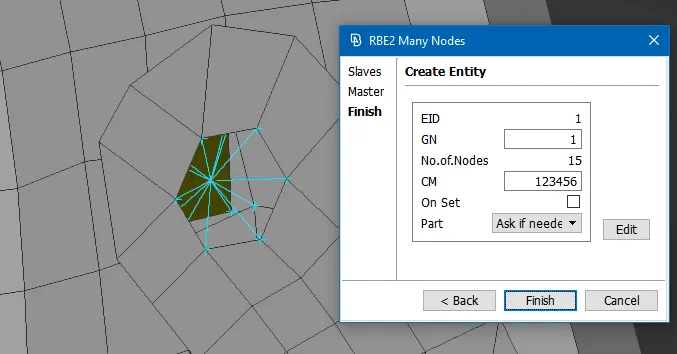
- All the slave nodes are bound to the master node and the RBE2 connection is represented by cyan lines. The window displays the element ID and Master node grid ID: GN. The total number of selected nodes is 15 and CM field shows the restricted degrees of freedom; where 1, 2, 3 represents the translational motion along X, Y, Z axes respectively and 4, 5, 6 is the rotational motion about X, Y and Z axes respectively. So this rigid connection locks all the degrees of rotation since it is a hinge component is bolted to the door inner panel.
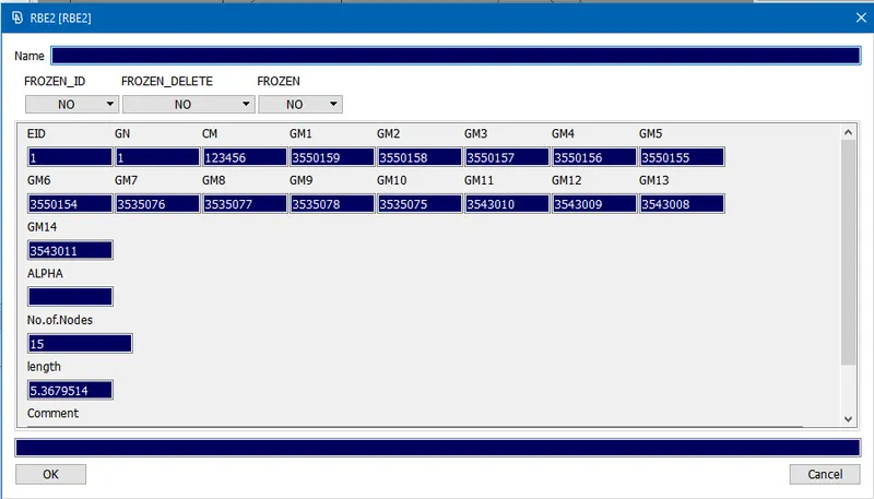
- This window displays all the information about the RBE2 connection with the click of the Edit option. All the slave nodes are having grid IDs allotted to them as GM.
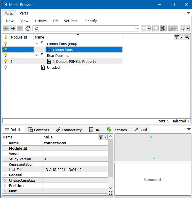
- For the creation of new part for connections, Ask always is selected from the Part field. Then with a click on the Finish, the Model Browser window appears as shown above.
- Right-click > New > Part is selected and named as connections and added to a group. And all the new connections are added to this part model.
- Using connection manager
- In this method, 3D point is initially created using TOPO > Points > On COG (Edges)
- As it can be seen, three layers of door sheet metal are to be bolted together. Hence the edges of the hole of the middle layer are selected using Loop selection tool. On confirmation, COG point is created.
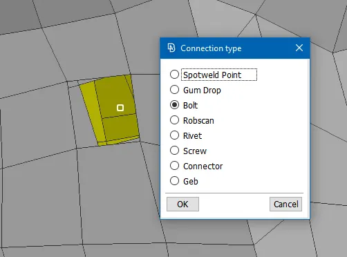
- Using Menu bar > Assembly > Convert (3D point), this COG point is converted to bolt connection type from the connection type window.
- Menu Bar > Assembly > Connection Manager function is used next to define and realize the bolt connection.
- On selection of the bolt point created by Convert tool, the following window appears
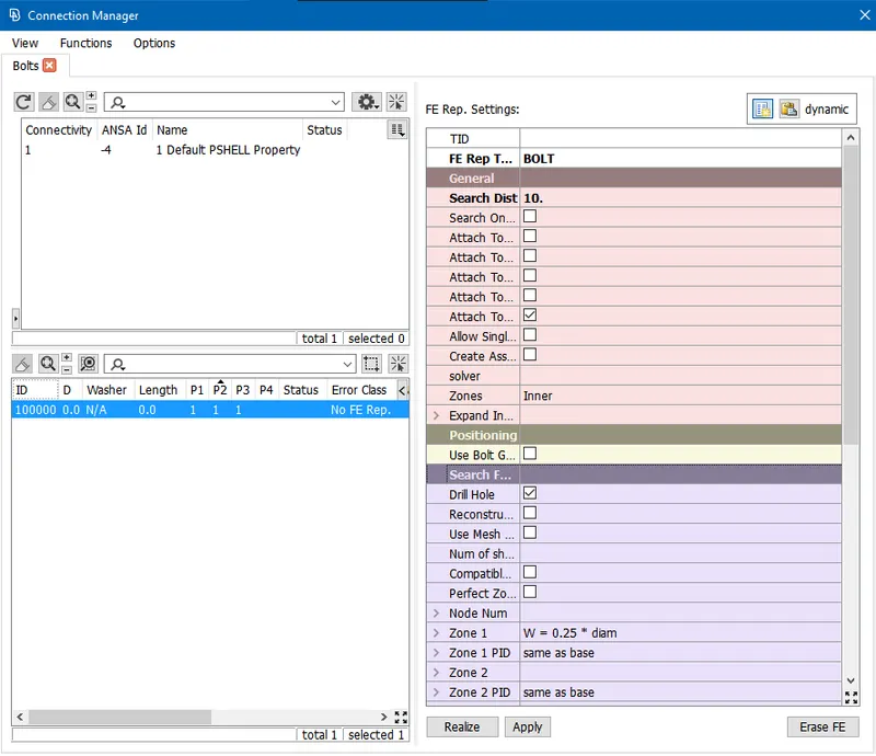
- Since 3 parts are bolted together, the PIDs of all the three parts are fed into P1, P2 and P3. This is done by right-clicking on header and entering PID value in modify field.
- Then FE representation type is selected as Bolt in FE Rep. settings panel.
- The search distance is set to 10 so that all the hole regions nearby falling under the search distance are automatically selected
- Zones are set to Inner type. Zones represent which nodes around the hole are connected by the bolt head or nut. Inner means that the nodes on the hole edges are only connected.
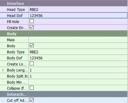
- The head and Body type are set to RBE2 and the Body DOF is set so that all degrees of freedom are restricted.
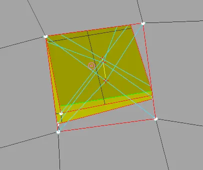
- This is how the connection is represented. RBE2 many node connections (represented by cyan lines) is deployed for individual hole nodes and RBE2 two nodes connection (represented by yellow line) is deployed for master nodes of different holes.
- Defining hinge connection:
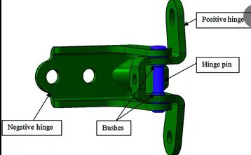
- The image shows the door hinge. The positive hinge and negative hinge are connected rigidly with hinge pin passing through. And this connection has only one degree of freedom. The same connection is replicated in ANSA using RBE2 function.
- Initially, RBE2 Many Nodes function is selected from NASTRAN module > ELEMENTs panel. The nodes of the positive and negative hinge hole perimeter are selected.
- The master node is created at geometric center. All degrees of freedom are restricted in CM field.
- The same procedure is repeated for holes on the bottom side.
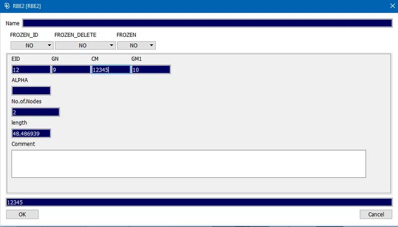
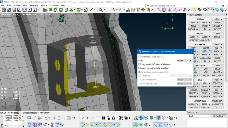
- The two master nodes are selected for RBE2 > Two Nodes function.
- Allow to pick already selected option is ticked in Element's definition parameters window and confirmed
- The above shown RBE2 NASTRAN entry card appears. It shows the information like master node ID (the node selected first): GN and slave node ID: GM1.
- In the CM field, '6' is omitted. Since the door is allowed to swing about Z-axis and restricted in all other ways, CM field is defined with 12345
- This creates a yellow connection line between two nodes as shown below that represents the hinge pin:
- Creating window glass connection:
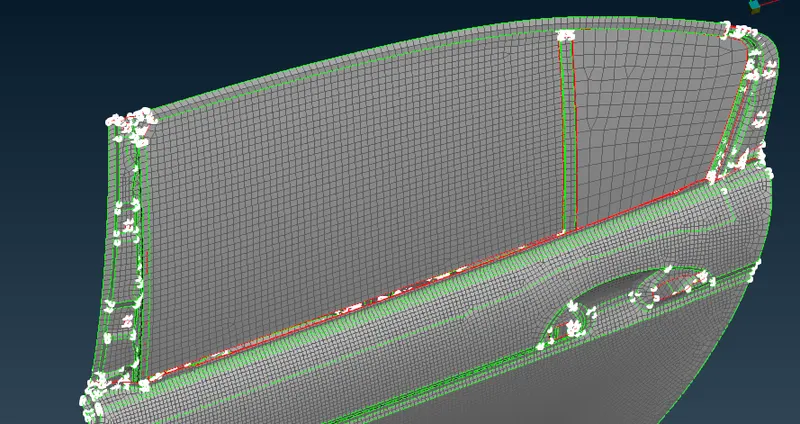
- It shows the window glasses of the rear door. The glass between the B-pillar and C-pilar can be seen. It has a partition that separates the glass into rear door retractable glass and vent glass. The retractable glass on the left is attached to the mechanism and it can move up and down. The vent glass on the right side is fixed. Both the glasses are attached to the weather stripping or window sealing rubber. Since the rubber is elastic in nature, it acts like a spring with a damping coefficient.
- The weatherstripping is available on all the edges of the glass. In order to create this connection, all the window glass edges are converted to curves using MESH > Perimeters > Feat2Curve function as shown below:
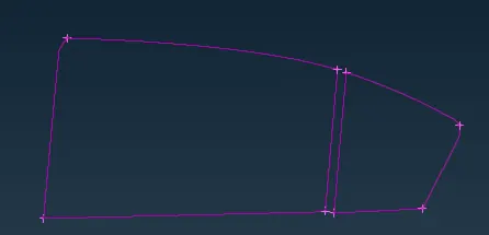
- Since the damping elements are also present on the inner side of the window at the bottom, the curves are Offset by 15 mm to the inner side using Utilities > Transform (Copy)
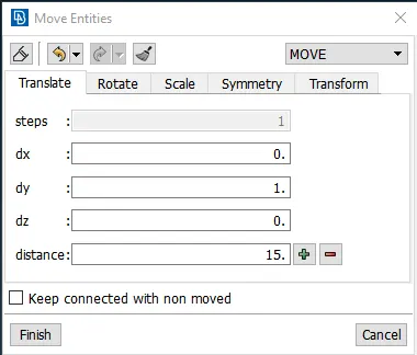
- Since positive Y-axis is directed towards the inner side of the door, dy is set to positive 1 value.
- All the curves are converted to spot line using Assembly > Convert (Curve) option.
- The spot line is defined as spring-damping element using Utilities > Connection manager
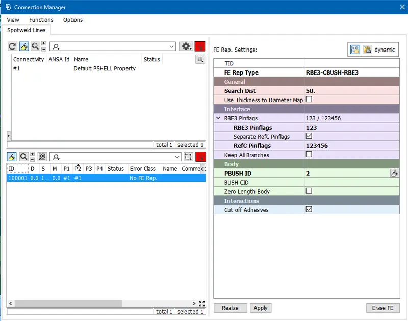
- The spot line is selected and confirmed. Then the connection manager window appears. On the left side, S is the distance between the adjacent spring-damper elements and it is set to 10 by right-click and entering 10 in modify field.
- P1 and P2 are the parts that are to be connected. P1 is considered to be the door panel and P2 to be the window glass. The respective PIDs are entered in modify field after right-clicking. Since no other parts are involved in this connection, P3 and P4 are ignored.
- On the right side, FE representation type is set to RBE3-CBUSH-RBE3. This type of representation defines the motion of connected parts considering the stiffness and damping coefficient of the CBUSH elements.
- The search distance is set to 50 or 100 mm. This makes sure that the corresponding grid points of two parts in this search range are connected.
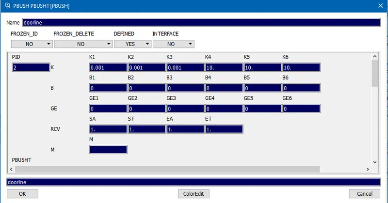
- PBUSH element is defined as shown below:
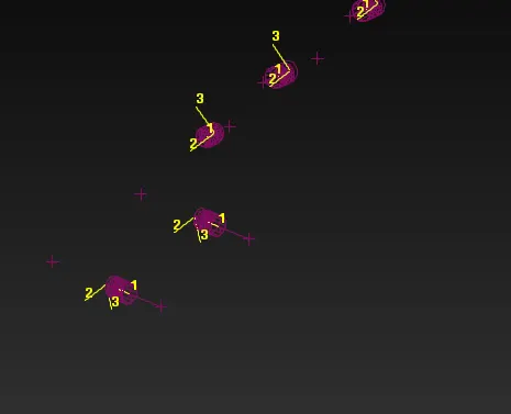
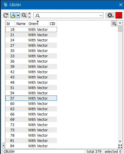
- As it can be seen, the CBUSH elements are randomly oriented, since all the elements are having local coordinate system. In order to align the local coordinate system with global coordinate system, all the CBUSH elements are selected from the window and right-click > Modify is selected.
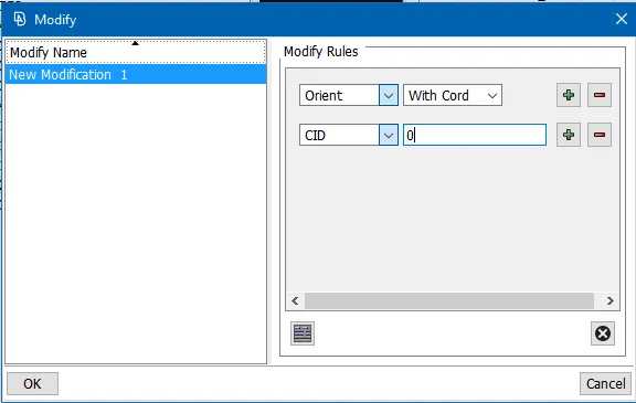
- In Modifying rules panel, Orient is set to With Cord and Coordinate ID is set to 0. This way local coordinate is the same as global coordinate.
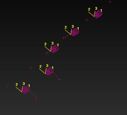
- After modification, all the CBUSH elements are seen to have the same orientation.
- Creating door handle connection:
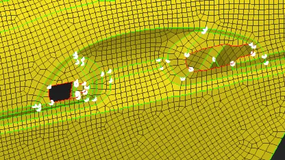
- These holes on the outer door panel are made to accommodate the door handle.
- These handle mounting holes are defined as rigid elements using NAS > ELEMENTs > RBE2 (Many Nodes)
- Both the rigid elements are connected using RBE2. This creates a master node at the center of two holes. This center is where the door handle mass is concentrated. The concentrated mass element is created using NAS > ELEMENTs > CONMi (CONM2) function.
- Using RBE2 function
-
-
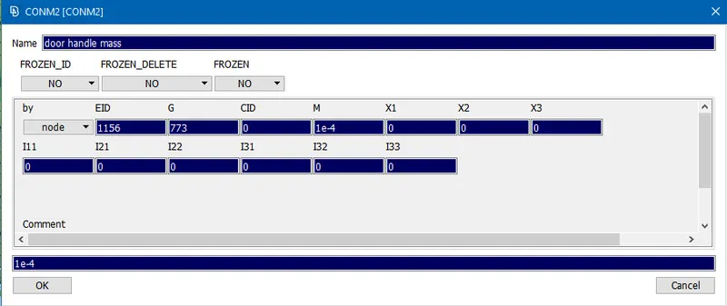
- This is the CONM2 entry card. This card seeks mass info of the CONM2 element.
- The mass of the door handle is assumed to be 100 grams. Since the mass is to be entered in tonnes format, 1e-4 is the mass in tonnes.
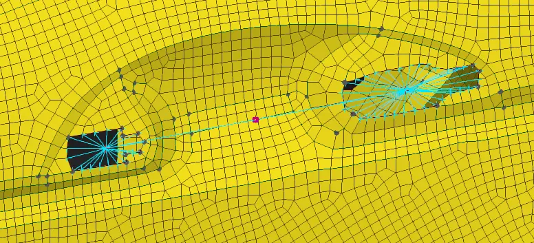
- This shows the final representation of door handle where magenta circle is the concentrated mass element.
-
Conclusion:
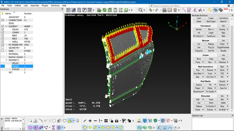
All the necessary connections are made to the rear door as shown in the image.
Learning Outcome:
- The difference between RBE2 and RBE3 elements is that the load applied to the RBE2 connection is evenly distributed to the slave nodes and the load on RBE3 connection is distributed on the slave nodes based on the distance: the closer the node to the load application point, the higher the stress on the node.
- Master node is the one with independent degrees of freedom and slave node is the one with dependent degrees of freedom
- RBE3 element defines the motion of reference grid point as weighted average of motion of previously selected grid points.