Week-7 Challenge: DC Motor Control
Problem Statement:
- Run MATLAB demo ‘Speed control of a DC motor using BJT H-bridge’. Modify the model such that armature current doesn’t shoot up when motor changes direction from forward to reverse.
- Refer to help section of ‘The Four-Quadrant Chopper DC Drive (DC7) block’. Compare it with H-bridge model.
- Make a suitable EV model using DC7 block and make result report.
- Explain in a brief about operation of BLDC motor
Solution:
1. Speed control of DC motor using BJT H-bridge:
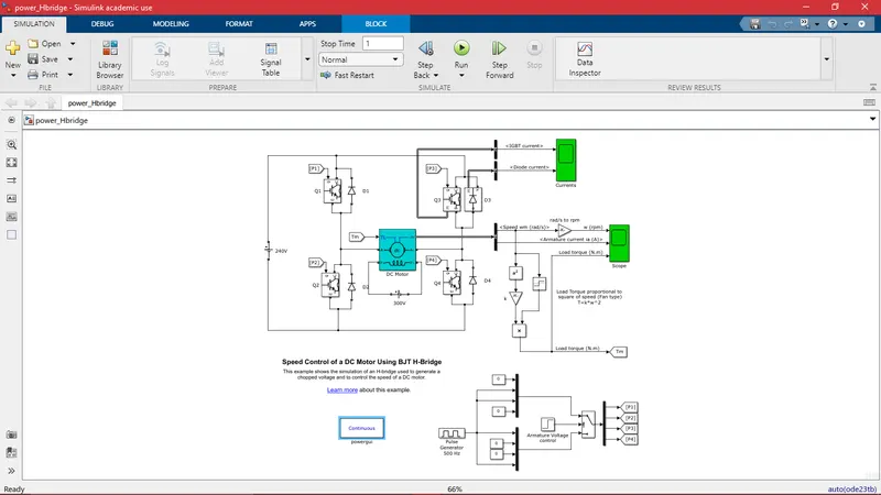
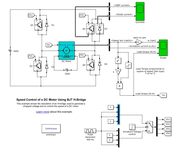
The Simulink model of the speed controlling circuit of DC motor with Bipolar Junction Transistor in H-bridge configuration is shown in the above picture. The DC motor armature and field connection are open. The field winding is separately excited with a 300V DC voltage source. There are four pairs of IGBT and diode. The IGBT current and diode current are taken as output at connection Q3 and displayed through the scope. And the armature current and motor angular velocity is taken as output from the DC motor output bus. The angular velocity of motor is converted to RPM through Gain block. The angular velocity is converted to torque by implementing torque-speed characteristics of the load.
The IGBT switches take Pulse Width Modulation signal as input from the Pulse generator block. Pulse generator is operating at a frequency of 500 Hz. Hence, the time period of a pulse is `T=1/f=1/500=2e-3`. The simulation time is 1 second and it is divided as 500 pulses for a second.
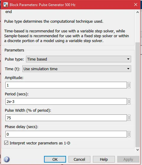
This block parameter shows the Pulse Width Modulation signal value. It can be seen that single pulse time period is 2e-3 s. The pulse width is specified as 75% of the time period that is equal to 0.0015 s. This means that IGBT switches are fired during 75% of the pulse time period, 0.0015 s and the circuit is in freewheeling condition (switches are open and current circulates through the diodes) during the rest of the time period, 0.0005 s.
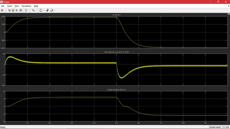
The above plot, showcases the behaviour of the motor under variation of applied voltage. As it is already known, the duty cycle of the DC-DC converter is set to 75%. It means that the average voltage applied to the motor armature winding is 75 % of the battery voltage. Initially, motor is at rest. It takes time to run at peak speed corresponding to the load torque and applied voltage. Back EMF `E_b` is directly proportional to speed of the motor and flux per pole. Since the DC motor is separately excited with a constant voltage source, flux per pole is constant.
Armature current is given by: `I_a=(V_(avg)-E_b)/R_a` where `V_(avg)` is the voltage applied across the armature winding; `R_a`is the armature reistance;
When the motor is starting, the speed at that instance is 0. Due to this, the back EMF is null. This allows higher voltage across the armature and higher current flows. The speed of the motor increases slowly due to the inertia resistance. This generates back EMF and reduces the voltage across the motor, which in turn reduces the armature current and stabilizes it.
When the motor is reversing, the voltage and armature current reverses immediately. However, the speed of the motor reduces to 0 from high speed and then reaches high speed in the opposite direction. During this time, the back EMF will be in the same direction as the reversed voltage until motor speed cross 0. The armature voltage will be higher compared to that when the motor is starting. Hence the armature current flowing through the motor winding will be much higher. It is evident in the plot.
At 0.5 s, the reverse voltage is applied to the motor. Q3 and Q2 IGBT switches are fired and Q1 and Q4 switches are open. So the current from the battery flows to the motor in the reverse direction. During that instant, the armature current is seen to shoot up to 65 A. And at t=0, when the motor is starting, the armature current shoots up to 35 A.
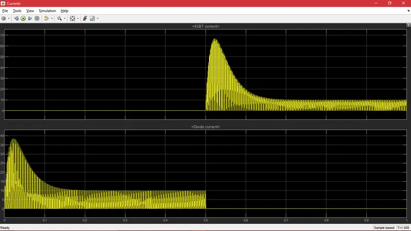
The above figure shows the current variation in IGBT Q3 and diode D3 during the simulation time. It can be seen that during the first half of the time, the current is flowing through the diode D3 and it is fluctuating between high value and 0 value. This is because, during the first half of the simulation time, diodes Q1 and Q4 are fired and the current freewheels through diodes D3 and D2. Each pulse is of 0.002 s, and Q1 and Q4 are open and current freewheels through D3 and D2 during the last 0.0005 s of a pulse. In the second half of the simulation time, Q2 and Q3 are fired and when these two switches are open, the current freewheels through the diodes D1 and D2. Hence, in the second half, D3 diode current is null in the above plot and Q3 IGBT current fluctuates in the pulses of size 0.002 seconds. Since the IGBT switches are closed for the first 0.0015 seconds of the pulse time period, IGBT current reaches high value in first 0.0015 s and is null during later 0.0005 seconds of each pulse.
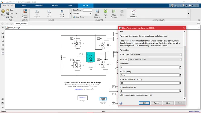
In the above model screenshot, the modification made to the model is highlighted. In the Pulse Generator block, the Duty cycle is reduced to 50% from the initial 75%. In this way, the average voltage level drops to half of the battery voltage. Due to the lower voltage, lower current is passed through the armature winding.
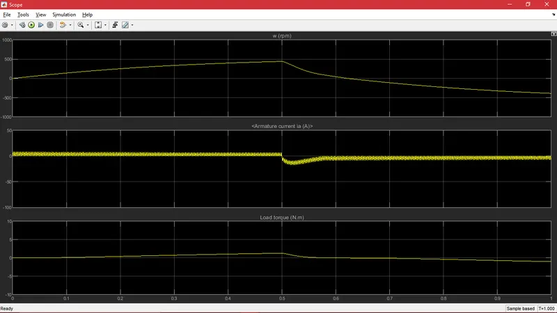
In the armature current plot, it can be observed that, at 0.5 s when the motor direction reverses, the armature current does not shoot up as seen in the previous plot.
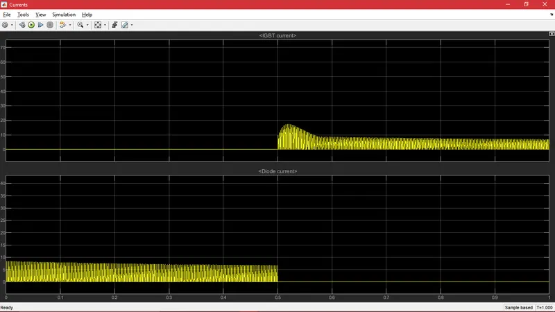
The above plots also indicate the same phenomenon. The current flow reduces in the switches and diodes due to lower applied voltage.
2. Comparison between the Four-Quadrant Chopper DC Drive and H-bridge model
| Four-Quadrant Chopper DC Drive | H-Bridge model |
| It works in the four quadrants, namely: Forward motoring, forward braking, reverse motoring, reverse braking. Forward braking is achieved by utilizing the kinetic energy of the load by running the motor as a generator. In this way, the mechanical energy of the load is consumed and converted into electricity, and the load comes to rest. There is no possibility of the load running in opposite direction in this type of DC drive. Works the same way for reverse braking. | It works in two Quadrants, namely: forward motoring and reverse motoring. Forward braking is implemented through reverse motoring until motor comes to rest. If the reverse motoring is discontinued when motor speed is zero, then the motor start running in the opposite direction. Works the same way for reverse braking. |
| DC motor runs as a generator during forward and reverses braking and as motor in forward and reverse motoring. So the generated power can be fed back to the battery. | DC motor does not run as a generator at all. As no electricity is generated, power flows only from battery to the Dc motor. |
|
Pulse width modulation signals are generated by Proportion-Integral speed and current controllers. The vehicle drive cycle data is provided, that is the required speed of the vehicle at different instances of time. This data is called as reference speed. The actual speed of the motor takes and subtracted from reference speed to get the error signal. The error signal is manipulated in the PI controllers to generate PWM signals. PWM signal is an essential control signal that contains the data such as frequency, pulse ON time and pulse OFF time. This signal when fed to IGBT power switches gets translated to stepped-up or stepped-down voltage that intends to diminish the error signal or to reduce the difference between the reference and actual speed of motor. Hence, the pulse width is not constant and alters as required motor performance. |
PWM signals are generated using pulse generator and logic block. It is pre-determined and is not flexible with changing conditions. It does not take into account the required speed of the motor or the load. Pulse generator takes pulse time period and pulse width percentage as input, which is fixed for a particular simulation. |
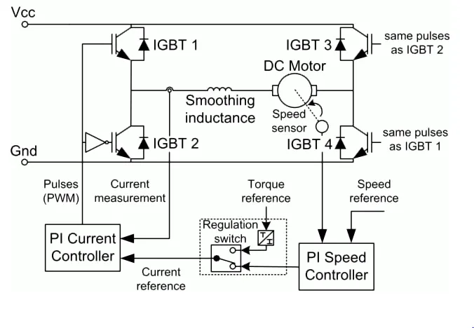
3. EV model using DC7 block:
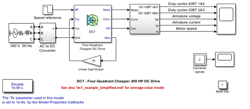
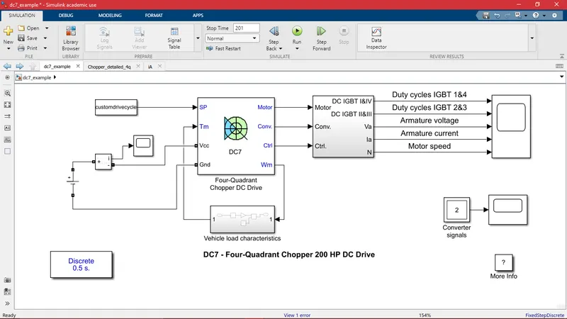
In the above figure, we can see that DC7 block is used to model the 200HP DC drive. The reference speed is taken from the ramp block with initial and final motor speed. The power is received from the 3-phase AC supply. In order to model an EV, the reference speed is replaced with a custom drive cycle with incremental time in seconds in the first column and the required vehicle speed in mph in the second column of an excel file which is imported into the Matlab workspace. Since EV cannot run with the ac power source, the power source is replaced with constant voltage DC battery (300V). Current measurement block is used to plot the current drained and supplied throughout the drive cycle. The positive terminal of the battery is connected to Vcc and negative terminal to Gnd of DC7 block.
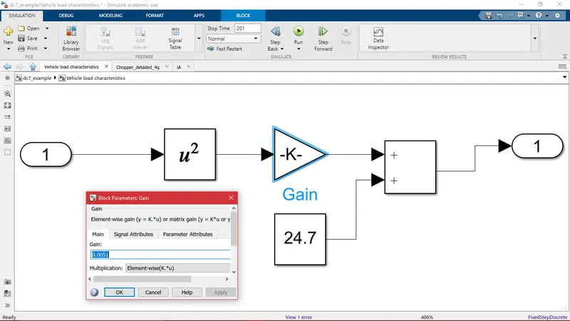
The vehicle torque-speed characteristics are taken into account by building a subsystem. The torque-speed equation used is: `tau=24.7+0.0051omega^2`. This equation is converted into a set of blocks. The angular velocity of the motor is taken as input. A square block is used to calculate the square of angular velocity. The gain block is used to multiply 0.0051 to it and Add block is used to output the sum of both values that returns the required torque of the motor.
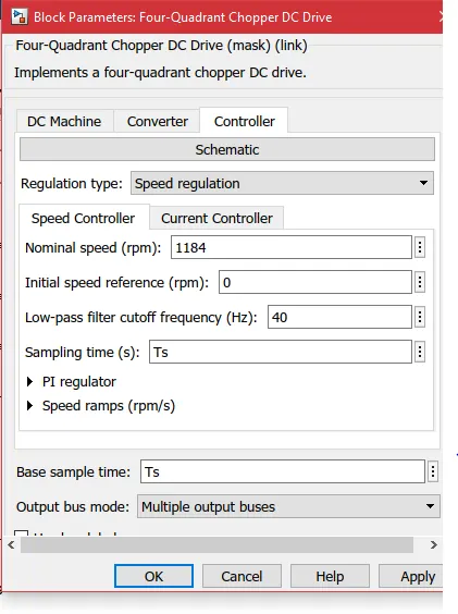
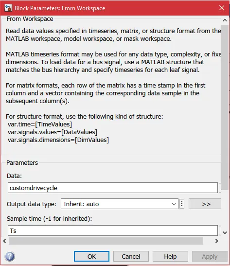
The sampling time variable 'Ts' is changed from the workspace to 1 s. Subsequently, the sampling time of the drive cycle block and DC7 block is also taken as the same.
Output:
The following output is obtained:
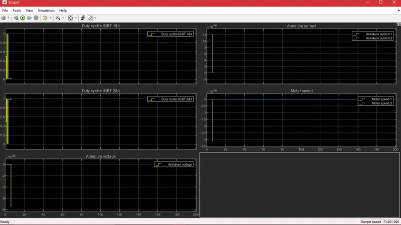
This shows how the motor responds to the drive cycle and how the IGBT duty cycles are determined by the PI controllers to fulfil the vehicle requirements.
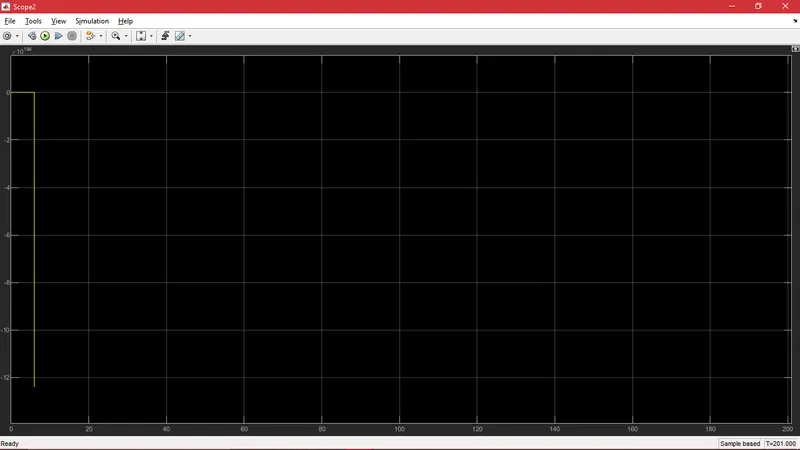
This plot is obtained from the current measurement block, to see how the current flows in and out of the battery.
4. Operation of Brushless DC motor:
The working principle of Brushless DC motor is same as Brushed DC motor. That is, the working of both the motors are based on the position feedback of the rotor. In BLDC, due to the absense of mechanical commutator, hall sensors are used to determine the position of the rotor. Whenever the permanent magnet mounted on the rotor pass the hall sensors, they generate high or low output signal.
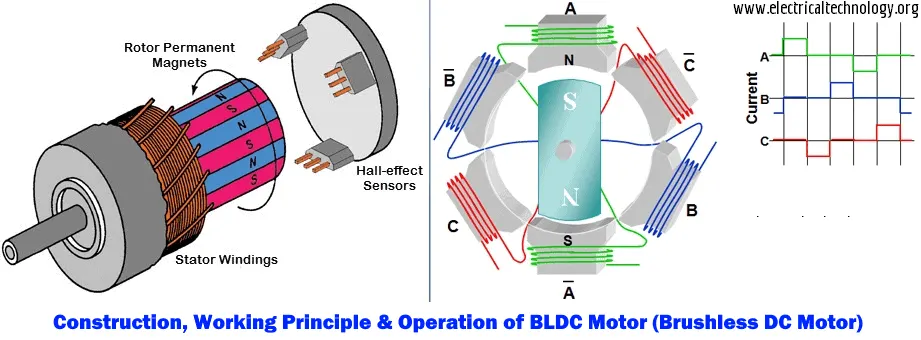
The working principle of the BLDC motor is Lorentz force: Whenever a current-carrying conductor is placed in the magnetic field, it experiences a force. Since the current-carrying conductor is made as a stator, it is fixed and cannot move. As a result, the permanent magnets experience a reaction force that rotates them.
The DC supply to the stator winding is electrically switched. The stator is a combination of three pairs of winding. The DC supply to these winding pair is separate and has a phase difference. In this way, the DC supply is inverted to AC supply in the form of trapezoid.
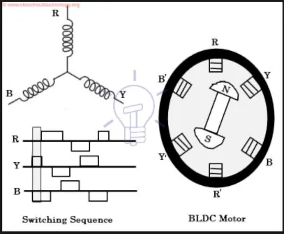
Consider this position of the rotor. The hall sensors determine the position of the rotor by sensing the magnetic field and supply this information to the switching device. In the switching device, the dc supply is split to R, Y and B windings. As it can be seen in the signal, R-winding is not energized, Y-winding is supplied with the current and B- winding is negatively energized. Correspondingly, YY' pair form electromagnetic north-south pair and repel the rotor towards the counter-clockwise direction and BB' pair form the south-north pole and attract the rotor in the counter-clockwise direction.
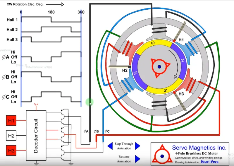
This figure shows a 4-pole BLDC motor. In the 4-pole configuration of the rotor, the same poles are arranged on the opposite side of the rotor. The position of the hall sensors are marked as H1, H2 and H3 which are placed with angular displacement of 120 degrees. On the top of the left column, the signals generated by respective hall sensors can be seen. Hall sensors generate a low signal when they come across the north pole and a high signal when they come across the south pole. The rotor position is in such a way that H1 is positioned in between the north and south pole. Hence it generates a signal that is shifting from low to high. H2 is across a north pole, hence generates a low signal and H3 is across the south pole, thus generating a high signal. These hall sensor outputs are fed into the controller, which then generates appropriate control signals to direct the power electronic switches. The switches then supply the power to the phase windings, which can be seen on the left column. From the figure, it can be made out that these phase windings are in star-connection.
Reference: