Week- 5 - Solid meshing
Aim:
To check for the geometrical errors of the rearview mirror and mesh the surface of the component with 2D elements conforming to the following criteria:
|
S.No |
Quality Criteria |
Value |
|
1 |
Target/Average length |
1 |
|
2 |
Minimum Length |
0.5 |
|
3 |
Maximum Length |
2 |
And to mesh the volume of the component with tetra elements conforming to the quality of Tet collapse of 0.2.
Procedure:
- Geometry clean up:
- The isometric view of the rearview mirror is shown below
- The component consists of 4 different parts defined by 4 different PIDs
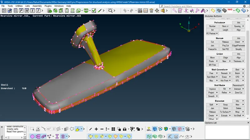
- The orientation of the faces of the component is incorrect
- There are numerous geometric errors like single cons, needle faces and triple cons
- Reducing the nodal length using MESH > Length > Perimeter and set the length as 1 mm
- Performing the topo clean up using Topo function in TOPO deck under Faces section and selecting the whole part
- Checking for the geometrical errors using Menu bar > Tools > Checks > Geometry
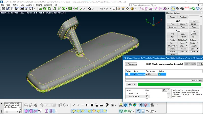
- The topological errors are rectified using the auto-fix option and the image shows a clean topo part
- Defeaturing:
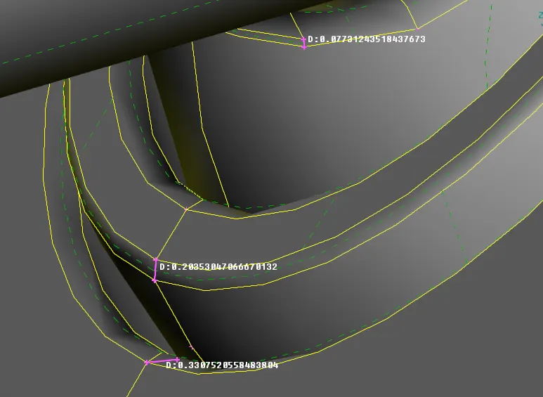
- The measurement of small fillet regions is done to verify if the size violates minimum length criteria.
- Menu Bar > Utilities > Measurement and selecting the nodes of interested regions
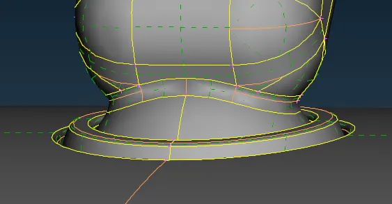
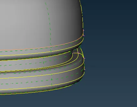
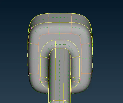
- Few fillet regions are of width less than the minimum length criteria, hence these double cons are erased using TOPO > Faces > Cut and right-click
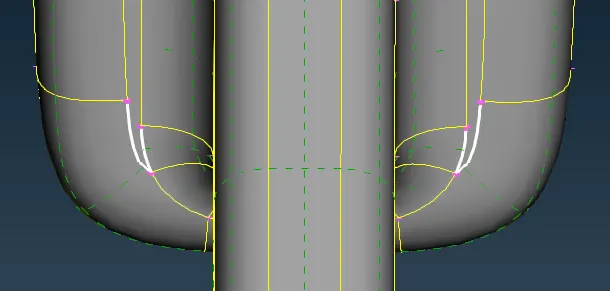
- The highlighted features lines are seen to be converging. Since this will result in failed elements due to minimum length, these feature lines are eliminated as shown below:
- Setting the quality criteria:
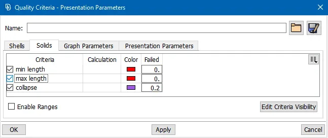
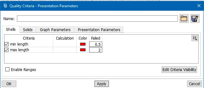
- The quality parameters for the mesh is set in Utilities > Quality Criteria
- In the Shell section, tria and ortho tria element requirements are set. The side lengths of the trials should be within the range of 0.5 mm to 2 mm
- In Solid section, tetra element requirements are set. Collapse is defined as minimum of : `(h/sqrt A)/1.24` where h is the distance of a node from the opposite face and A is the area of the opposite face. Collapse value is set to 0.2. Hence if the collapse value of a tetra element is below 0.2 then the element fails for quality.
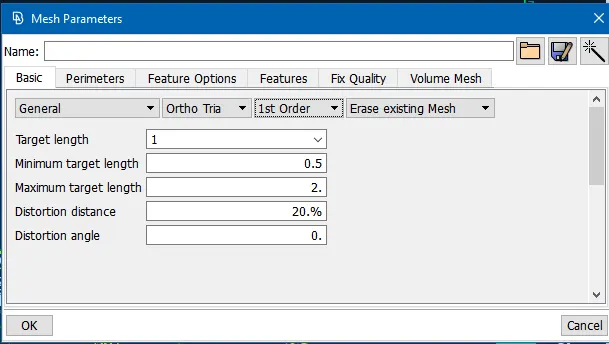
- The mesh parameters are set in Utilities panel.
- The average required element side length is set to 1 mm and the element type is set to ortho tria.
- Meshing:
-
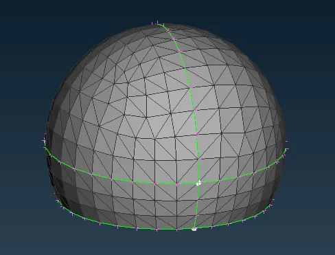
- In the Menu bar > Lists > Property, a PID is selected and "Show only" is chosen on right-click
- The part is a globular structure: ball of the ball joint system. Since the surface is curvy, it is meshed with ortho tria elements
- MESH > Mesh Generation > Spot Mesh function is used for 2D meshing. The visible entity is meshed on middle click. In the options List, the elements type is set to ortho tria by default.
- Ortho tria is chosen over the normal tria element since ortho tria elements produce much precise result during analysis. Since the ball is under shear stresses, detail capturing mesh elements are preferred.
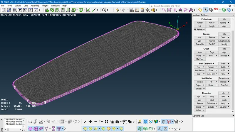
- The next part is selected from Property card with the Show Only option. The part is the back panel of the rear-view mirror.
- The corner entities are captured using ortho tria and the rest of the plane entities are captured with normal trias
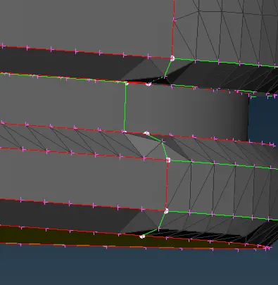
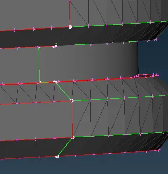
- The fillet region has raised edges. Since it is a surface deformation, it is unaccepted. Such deformations are fixed using MESH > Shell Mesh > Reconstruct function. This gives the following result:
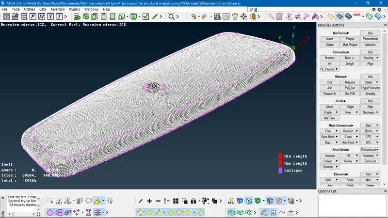
- This part represents the panel of the rearview mirror with mounting for ball joint.
- The globular structure and the corner entities of panel are captured with ortho trias and the rest of the plane elements are captured with normal trias.
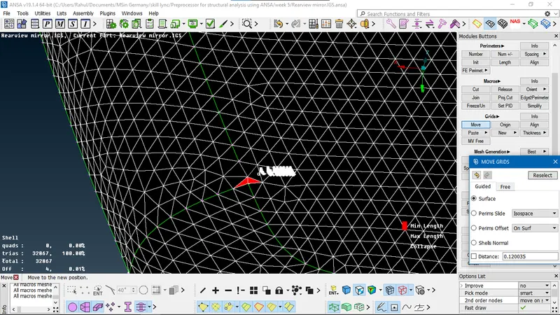
- This component has few OFF elements for violating minimum length error
- These elements are fixed by MESH > Grids > Move function. This function moves the node / intersection of the grid along the surface on which the mesh is generated.
- As the element is failing because of the shorter distance between the node and opposite edge, the node is moved away from its opposite edge and subsequently length is increased.
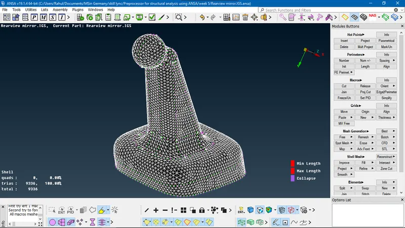
- The next part ID is selected. This part is the mounting end of the rearview mirror. The base of this part is attached to the top roof of the vehicle.
- The globular structure, fillet region and corners are meshed with ortho trias and other entities are meshed with trias using Spot Mesh function
- The failing elements are cleared off using Reconstruct function
-
- Defining volume:
- ANSA does not consider the existing volume entities as closed volume. Hence the parts are to be declared as closed volumes using VOLUME MESH > Volumues > Define (Manual)
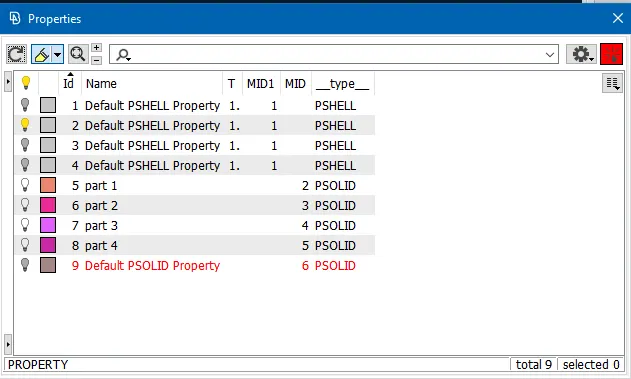
- The individual visible parts are selected and on confirmation, Property card appears. Since the available PIDs are in Shell format, Solid PID is created by right-click > New > PSOLID
- The selected part is assigned to the newly created PSOLID PID.
- The same procedure is followed for all the parts as can be seen in the Property card below:
- Volume Meshing:
- Volume mesh is the creation of mesh inside the volume of the component. The mesh elements on the surface are extruded through the thickness of the component
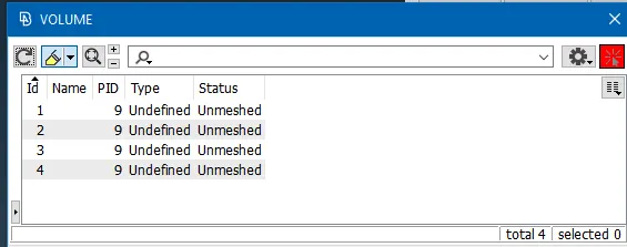
- This is the List function is available in VOLUME MESH > Volumes
- It lists out the defined volumes. Since the volumes were defined earlier, all the four volume entities are listed in it.
- In order to generate volume mesh, right-click > Mesh > Tetra FEM option is selected. The same procedure is followed for the rest of the entities. The mesh status is reflected below:
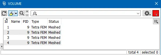
- The volume mesh can also be performed using VOLUME MESH > Unstructured Mesh > Tetra FEM
- Tetra FEM is a meshing algorithm that is much more precise and comparatively slower than Tetra Rapid algorithm
- This algorithm forms tetrahedral elements throughout the volume of the component. If the quads are available on the surface, pyramids are formed for the first layer.
- The maximum growth rate is set to 1.2 by default and the range is 1 to 3. And the other quality parameters are same as Quality Criteria
Conclusion:
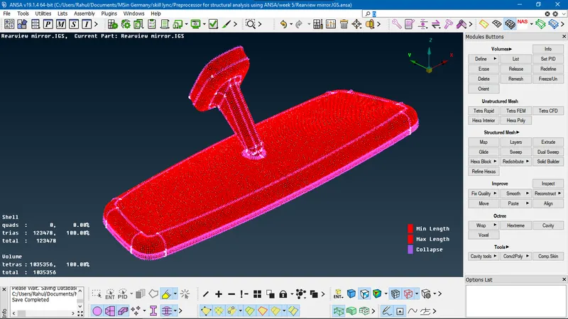
The shown volume mesh is obtained having 0 quads on the surface and 0 OFF elements. There were no Tet Collapsed elements were encountered in the mesh. Additionally, there are no raised edges or Kinks formed on the surface.
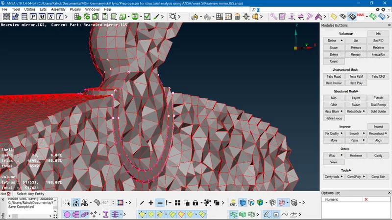
This image shows the interior meshing.
Learning Outcomes:
- The Tetra FEM algorithm gives better results than Tetra Rapid. While Tetra Rapid is faster.
- The Volume mesh quality depends on the surface mesh quality. The solid mesh has associativity with shell mesh. If the meshing on the surface is erased, it automatically erases the 3D mesh.
- If all the parts of the component are defined with single PSOLID ID, it results in the Penetration : Intersections error. It is because the surfaces of adjacent parts are very close. This error is resolved by defining different PSOLID IDs to different parts and meshing them separately.