Advanced Sheet Metal Design Using NX Cad Challenge_6_Bracket
Title:
Design of Bracket using Siemens NX
Objective:
- Modelling the base of the bracket using contour flange in sheet metal application
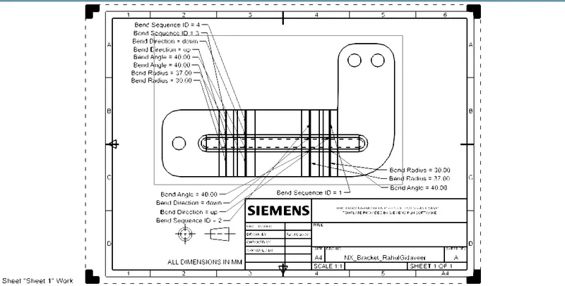
- Creating the flat pattern of the bracket and importing it in the Draft application and obtaining 2D engineering drawing for the bracket
Introduction:
In the process of sheet metal modelling, the first step is usually to create the base of the model. The base can be generated in numerous ways. One of the methods is to create base by using Tab feature. This command generates a flat sheet metal base with default global value for thickness. The tab does not have any bends or any other feature. Other method of base creation is Contour Flange. Contour flange, unlike Tab that has straight-line profile, can have have any profile that may consist circle, line, spline or arc. This profile can be extended for any distance to form the width or length of base. Though the profile is 1D, Contour flange does not form surface, rather it automatically assigns global value for thickness for the base profile. This way the sheet metal base has intrinsic bends. The same method is used here and additional features like blends, bead and holes are added using corresponding commands.
Design Approach:
Description:
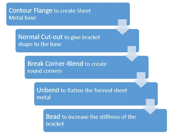
- Contour Flange
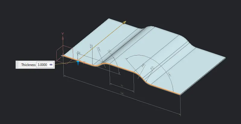
- This command forms the base sheet metal by extruding the profile normal to the plane of sketch
- The thickness is set to 3 mm and width is set to 200 mm
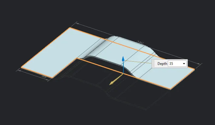
- Normal Cut-out
- The sheet metal material is removed outside the sketch area of the depth 35 mm
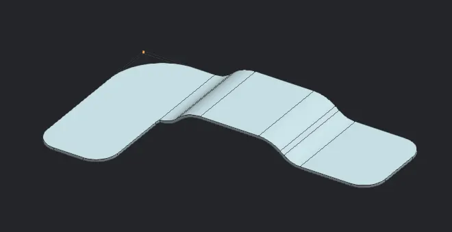
- Break Corner
- This command is used to convert sharp edges to round corners with given radius
- Unbend:
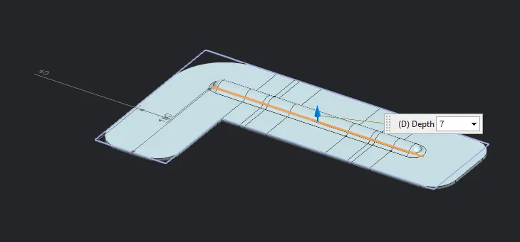
- Bead:
- It is used to create an elevation along the straight sketch line
- The depth of bead is 7 mm and radius is also 7 mm
- The die radius is set to 5 mm
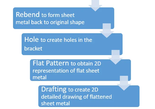
- Rebend:
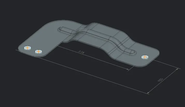
- Hole:
- General type of hole is created normal to the face
- Hole diameter is set to 20 mm and the depth - through body
- Flat Pattern:
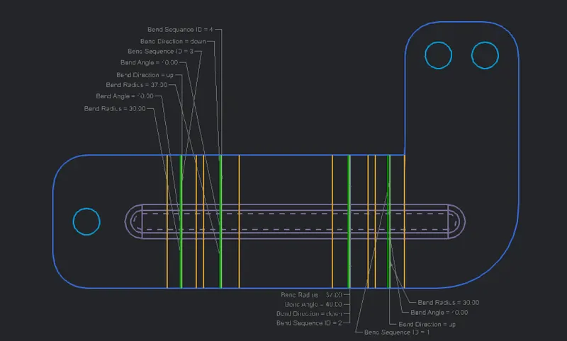
- 2D representation of Flat Sheet metal is created as shown below:
- Drafting
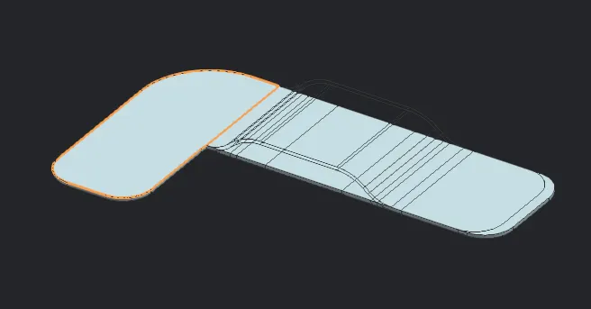
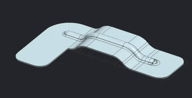
- The sheet size is set to A4 and base view is added to the sheet by using Flat Pattern from Sheet Metal application.
Conclusion:
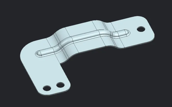
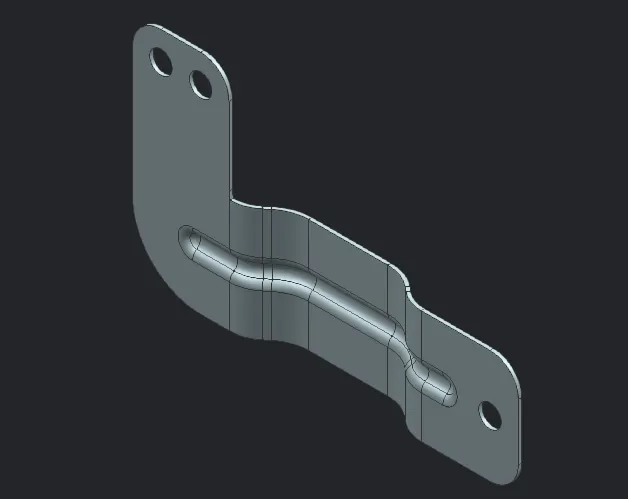
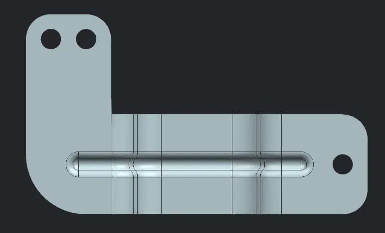
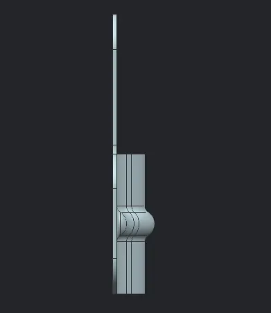
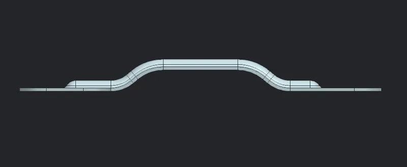
The sheet metal is modelled with good accuracy and final model images are shown below.
Arbitrary view:
Isometry view:
Top view:
Front View:
Right View:
2D Detailed Drawing: