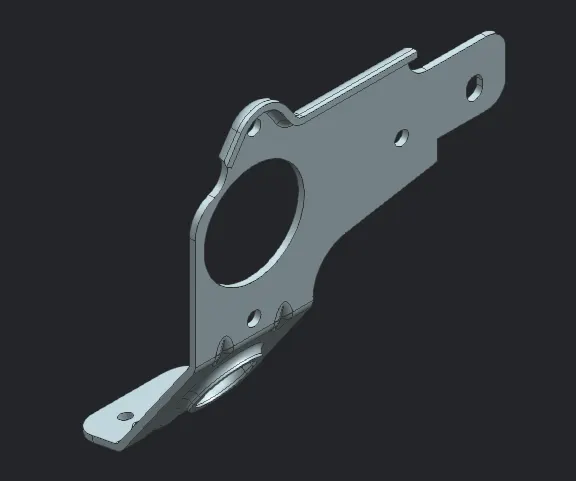
Advanced Sheet Metal Design Using NX Cad Challenge_7_ Metal bracket-II
Title:
Design of Sheet Metal Bracket including Advanced Flange and Gusset features in Siemens NX
Objective:
- To model the flange with right features and parametric values in Sheet Metal application
- To understand advanced flange and gusset feature
- To capture the images of th final model in various standard orientation
Introduction:
One of the methods to stiffen the sheet metal and prevent the spring back effect is to add gussets at the bend. Gussets are the stiffening features that connect the adjacent faces at the bends. Gusset restricts the joining faces at the bend to a particular angular orientation. Gussets allows the modeller to create:
- Punched or embossed shapes in the bend regions
- Gussets on the cylindrical bends created by features like dimple, drawn cut-out, solid punch, etc
- Gussets on cylindrical and non-cylindrical bends created by flanges:
- Cylindrical bend:
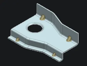
- Non-Cylindrical bend:
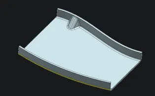
- Cylindrical bend:
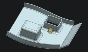
Gusset dialogue box parameters:
- Type:
- Automatic profile: This allows the user to create gussets of round or square form.
- User Defined Profile: This type allows the user to defined the curve connecting both the bend faces to form a gusset
- Bend:
- This asks the user to select a bend upon which gusset needs to be created
- Location:
- The user is required to select a face or a datum plane that is perendicular to the bend axis. This enables the user to locate the gusset across the bend.
- Section:
- This option is available under User Defined Profile. This lets the user to select the curve for gusset. This curve is the side profile of the gusset as shown below:
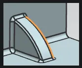
- Shape:
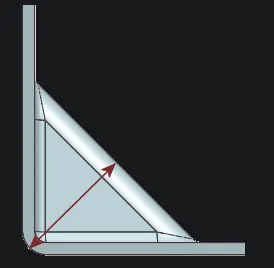
- Depth: Depth includes the distance between the outer bend radius and top face of the gusset as shown below:
- Round: This creates a gusset with round top face
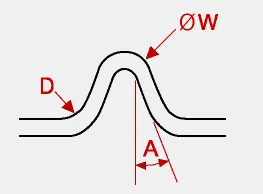
- Width (W) is the diameter of the outer face, D is the die radius and A is the side angle of the gusset
- Square: This creates a gusset with square top face
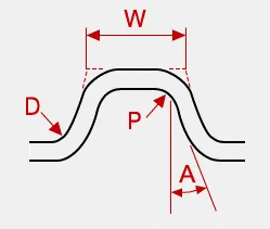
- W is the with of the top face, P is the punch radius, D is the die radius and so on
- Depth: Depth includes the distance between the outer bend radius and top face of the gusset as shown below:
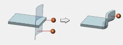
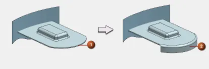
Another advanced flange explored in this modelling process is advanced flange. Advanced flange is used to create flange along an edge or reference face that can be curved. This feature also allows the user to create flange along connected chain of edges.
- Advanced flange can be created by using reference plane as shown. In this case, base edge is selected based on the direction of flange needed and reference plane is selected that defines the angle of bend and shape of the flange.
- Advanced flange can also be created using by value option. This allows the user to select the base edge which defined the shape of the flange.
Design Approach:
Description:
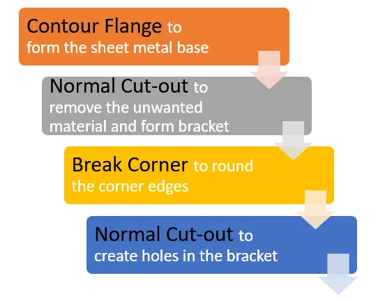
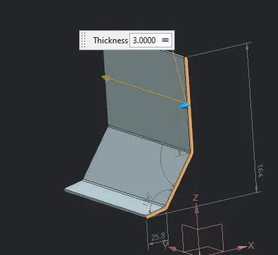
- Contour Flange
- This command creates the base of sheet metal with intrinsic bends of global value 3 mm
- The thickness of the model is 3 mm and the width is set to 158 mm
-
- Normal Cut-Out
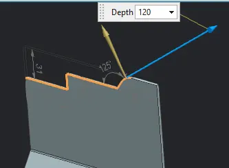
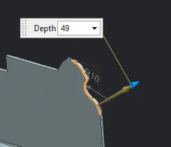
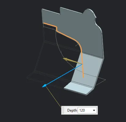
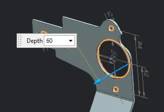
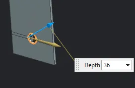
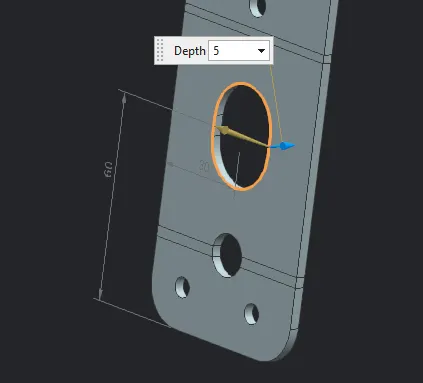
- Profile is drawn on the upper face of the base sheet metal to give the appropriate shape to the bracket and remove the material at holes
- Depth of cut is set to 120 mm arbitrarily to cover the whole profile of the contour flange
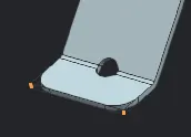
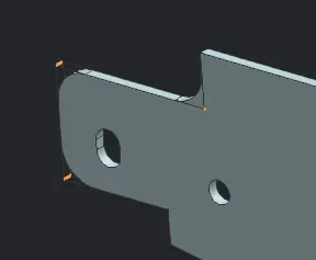
- Break corner
- This command is used to convert sharp corner edges to round corners with specified radius
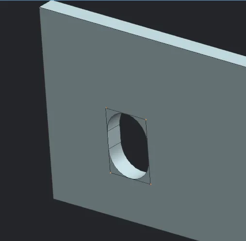
- The edges of the rectangular cut-out are selected and blend of 4 mm is created
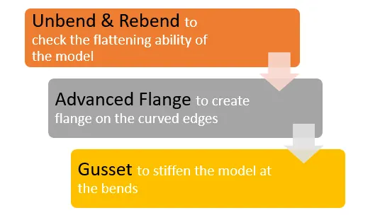
- Unbend
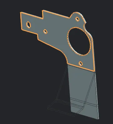
- The upper face is selected as a stationary face and bends are selected to flatten the model
- Advanced Flange
- This command is used to create flange along the curved edge of sheet metal.
- The flange length is set to 5 mm which includes web length and inner bend radius
- The other parameters like bend radius and web thickness are set to default value of 3 mm
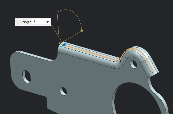
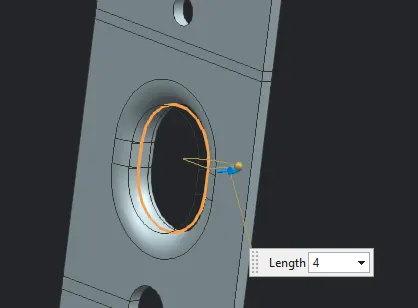
- In this case, the advanced flange is created along the periphery of the normal cut-out
- The length of flange is 4 mm
- Hole:
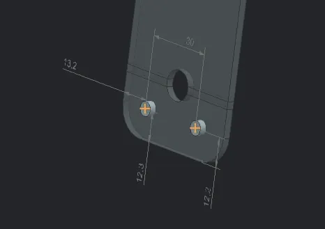
- Holes are created in Modelling application by specifying the sketch points on upper face
- Simple hole type of diameter 6 mm and depth same as the thickness of the body are created
- Rebend
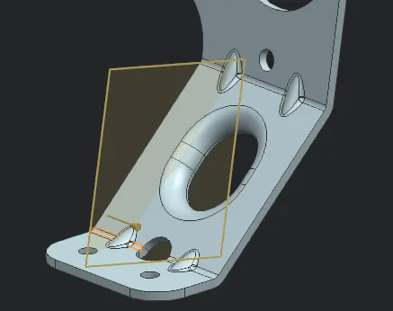
- Gusset
- The gusset is a stiffening feature created as bends to curb the spring back effect and prevents the sheet metal from deviating from the formed shaped.
- Gusset is formed by choosing the bend at which it needs to be created. Then a face is selected parallel to which gusset is required. Perpendicular distance from the face where gusset should be located can be additionally specified.
- The depth of gusset is set to 5 mm. This is perpendicular distance between outer curved face of the bend and top face of the gusset
- The gusset dialog box is set to automatic profile, the form is set to round.
- This form includes width as the diameter of the rounded face of gusset, set to 8 mm; Side angle is set to 45 degrees; dia radius is set to 2 mm
Conclusion:
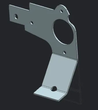
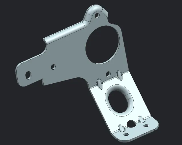
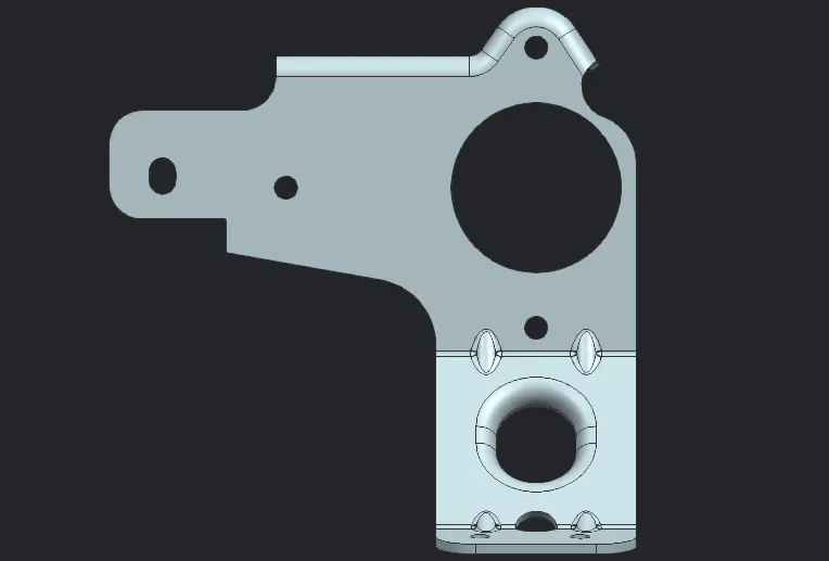
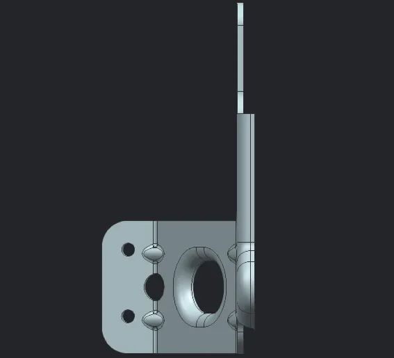
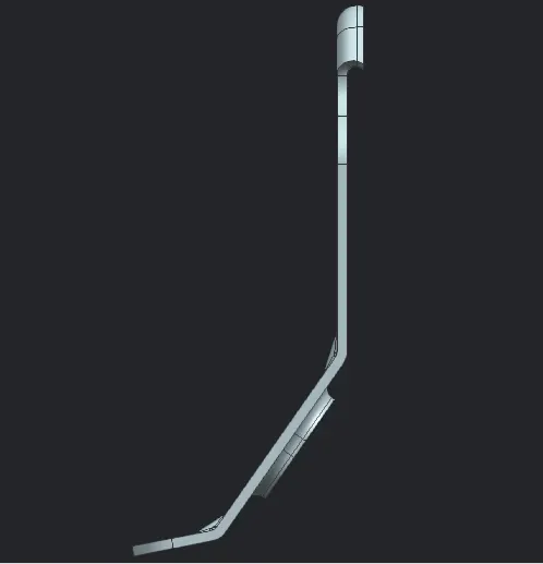
The bracket is modelled with appropriate features and parametric values with good accuracy. The resulatant model images are showcased below:
Arbitrary view:
Left view:
Top view:
Front view:
Isometric view: