Week 3 - 2D meshing for sheet metal
Aim: To take the mid surface for all the components for the given hood model after checking the geometrical errors and mesh the mid surface with the given element Quality criteria as mentioned below:
|
S.No |
Quality Criteria |
Value |
|
1 |
Target/Average length |
5 |
|
2 |
Minimum Length |
2 |
|
3 |
Maximum Length |
7 |
|
4 |
Aspect |
3 |
|
5 |
Warpage |
15 |
|
6 |
Skewness |
45 |
|
7 |
Jacobian |
0.7 |
|
8 |
Minimum Quad Angle |
45 |
|
9 |
Maximum Quad Angle |
135 |
|
10 |
Minimum Tria Angle |
30 |
|
11 |
Maximum Tria Angle |
120 |
|
10 |
Tria Percentage |
15 |
Procedure:
- The Hood model is imported into ANSA by going to File > Open > select the required file. The CAD model is in stp format.
- All the parts available in the model have unique Property ID and this can be checked in Lists > Property.
- The individual parts are shown below by right clicking over the part from Property and selecting Show Only option
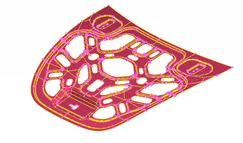
This is the bottom part of the hood having the thickness of 0.75 mm
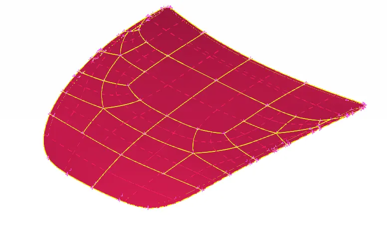
This is the top cover part of the hood also having the thickness of 0.75 mm.
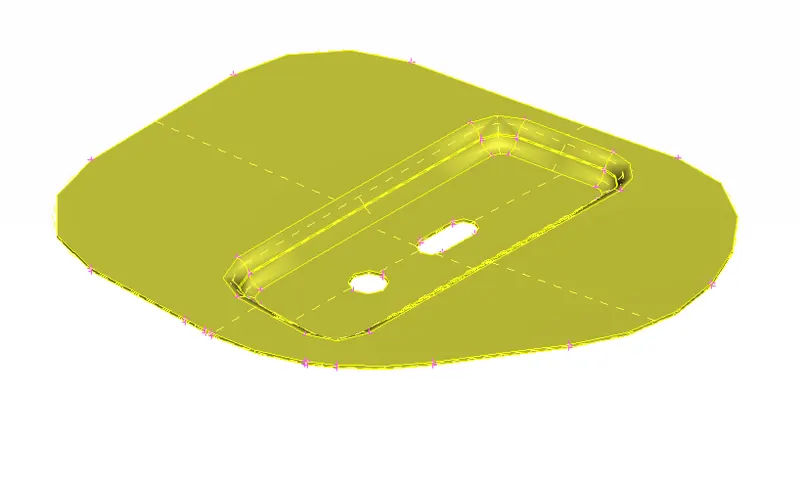
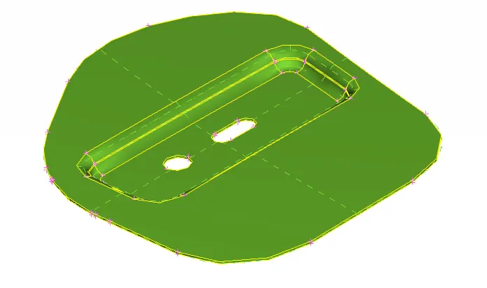
Both the above parts are hinges of the hood of thickness 1.2 mm
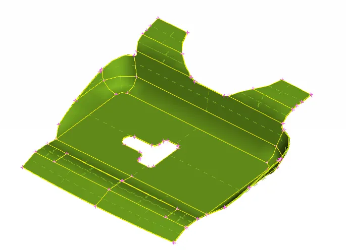
This is the Latch of the hood with the thickness of 1.2 mm
- The individual components are selected and processed
- Initially, the orientation of the component is corrected. The component can be wrongly oriented; the same side of the component can have surface normals directed in opposite directions.
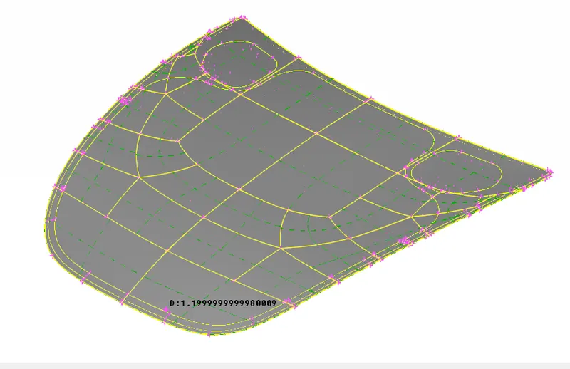
- ANSA shows the orientation of the surface through two colours. Yellow: The normal is into the plane of the surface; Grey: Normal is out of the plane of the surface
- This can be checked by going to Menu bar > Drawing styles > Draw mode > ENT. Draw mode shows the colour of the visible part. The yellow colour is negative and grey is positive.
- The image below shows a hood top cover. The same side is oriented in opposite direction. This is corrected by going to Topo > Faces > Orient (Visible) option. This option sets the uniform orientation direction to all visible faces
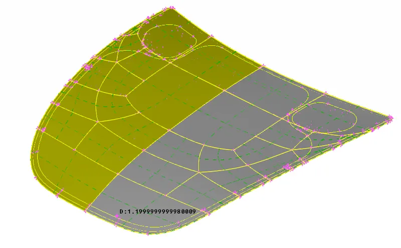
- After the Orient operation, the surface is uniformly oriented in positive direction as shown below
- The next step is to perform Geometry Cleanup. When the CAD model is opened in ANSA, due to translation issues from one format to another format, CAD model can have Geometric issues like needle face, collapsed con, triple con, cracks or deleted face. Resolving these issues is called Geometry Cleanup.
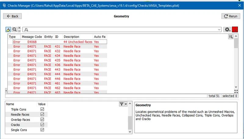
- To perform this action, go to Tools > Checks > Geometry. This operation requires a template. The template is a list of geometric issues that we are looking for to resolve.
- The below image shows the geometric errors for hood component. The Check Manager window shows 51 errors. The Execute button is pressed to perform geometry checks in this window. Auto fix option is available that cleans up the geometry automatically. Select all the errors and right-click over it, then select fix to clean the geometry automatically.
- Deifining the material:
- All the components of the Hood model are associated with material which defines the significant properties if the material like Young's Modulus and eleasticity.
- To check the material, go to Menu Bar > Lists > Materials
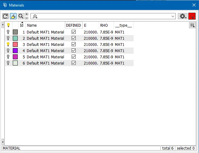
- Materials card appears and shows the list of materials. By default the DEFINED status is set to No. This status is changed to Yes. This allows the model to be exported out of ANSA with associated material properties.
- This action is shown below
- The next step is to create a mid surface. The midsurface is a thin shell description obtained from solid description by isolating the outer or inner skin of the solid description. Midsurface is an extract that defines the topology or the features of a solid part without the thickness. Midsurface is created in between the opposite surfaces that determine the thickness of solid part. There are two ways for mid surface creation:
- Manual midsurface creation by using Topo > Faces > Offset option.
- This function is used for created new surface by offsetting the available faces.
- On selecting this option, the user is prompted to select the faces for offset. All the faces are selected and confirmed.
- Then Offset value window appears. The value needs to be manually entered to half the thickness. Since the thickness of the part is 1.2 mm, 0.6 mm of offset value is entered and confimed.
- Then Confirmation window appears asking whether to keep or delete the original face.
- Automatic midsurface creation by using Topo > Faces > Mid. Surface (Skin) option
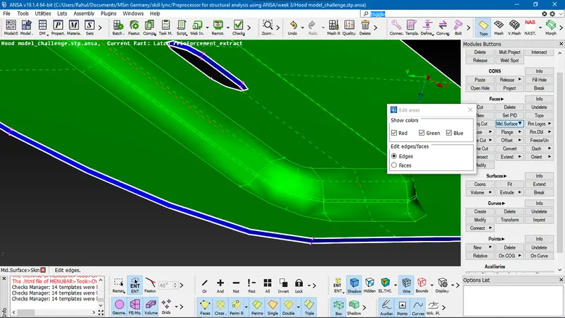
- Then the middle mouse click activates the automatic faces selection. All the faces visible on screen are selected and confirmation is requested from user.
- Edit areas window appears next, as shown below. The two sides of the solid component are represented by Red and Green colour and the thickness is shown by blue colour. If there is any discrepancy, then it allows for manual assignment of faces' description
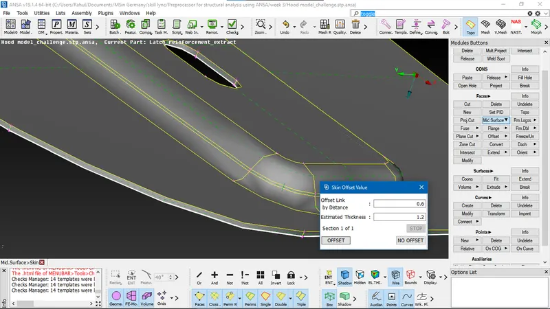
- After the selected areas are confirmed, the thickness is estimated and based on this the offset distance is automatically set to half the thickness as shown
- In this option, the original faces or the solid description is deleted without confirmation. This is prevented by deselecting Delete Orig. Faces option. Or the deleted faces can be retrieved by using Topo > Faces > Undelete option.
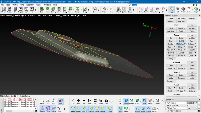
- The generated midsurface is shown:
-
- Further, Part ID (PID) is generated for the midsurface
- This is done by Topo > Faces > Set PID option
- Selection window appears. Faces/Shells option is selected and all the faces of the midsurface are selected.
- On confirmation, Properties list appears. Right-click on this list and select New. This enables the user to create new ID.
- Then the Property card appears. The name of the component is set in Name field and thickness is assigned as 1.2 mm. All other values are kept default.
- Then Ok is clicked back in the property list to confirm the creation.
- Setting the quality criteria
- This option is available in Menu Bar > Utilities > Quality criteria or the shortcut key is F11
- This option allows the user to set quality criteria for the mesh elements. The mesh elements consists of Quads and Trias. For the meshing to be proper, the mesh elements are required to be of good shape and size. The goodness of the meshing can be defined by quality criteria option.
- On selecting this option, Presentation Parameters window appears. The shells tab is selected since the midsurface is a thin Shell description. The given criteria is selected and entered as shown below. And the rest of the qualities that are not concerned are hidden.
- The selected qualities are
- Aspect ratio: It is the ration of maximum length to minimum length of element. It is set to 3, hence the longest side of element can be three times the shortest side.
- Skewness: This defined the shape of the element. For Quad: skewness = 90 - `theta_(min)`; For Tria: skewness = angle between Meridian line and mid mode line;
-
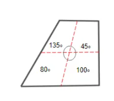 Minimum angle is selected this way for the quad
-
- Warpage: This is only for the quad element since it can bend and exist in 2 different planes. Warpage is the angle made by those two planes. It is set to 15 degrees. If the quad angle transcends 15 degrees then it fails for warpage.
- Jacobian defines how ideal is the element shape. If the shape of the element is idea, its Jacobian is 1. If the shape is not ideal, then the Jacobian value defined the deviation of element from ideal shape.
- min length is set to 2 hence the element side length cannot be less than 2 mm
- max length is set to 7, hence the side length cannot be more than 7 mm
- triangles % defines the maximum amount of tria elements that is allowed for total mesh elements.
- Then to save the criteria, Apply and Ok is clicked
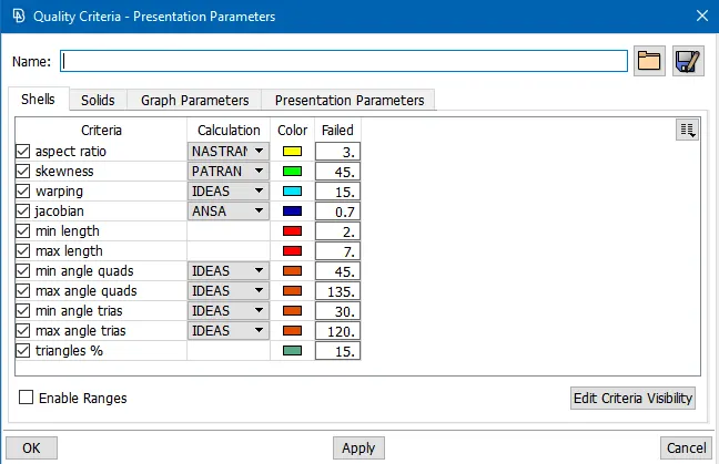
- Setting Mesh Parameters:
- This option is available in Menu Bar > Utilities > Mesh Paramers:
- Mesh parameters window appears. Under the Basic tab, Mesh type is set to General, mesh elements is set to Mixed (Quads and Trias), mesh elements type is set to 1st Order.
- Target length specifies the ideal length of element: 5 mm
- Minimum and maximum length is set according to the quality criteria.
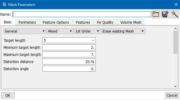
- Setting the element length for meshing:
- This option is at MESH > Perimeter > Length
- It is used to set the element length at perimeter and macro ares.
- On selecting this option, selection window appears giving Perimeter and Macro as options.
- Select Perimeter and select the whole midsurface with box selection and confirm.
- The length parameters window appears, enter 5 in length field and confirm.
- This creates nodes on the perimeters at every 5 mm since target length of element is 5 mm.
- Defeaturing
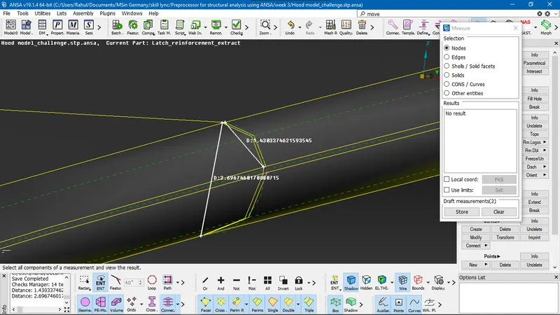
- This image shows the requirement of defeaturing. The hemmed boundaries of the Hood top cover has length of 1.43 mm. This is less than min length requirement of 2 mm. Since the elements of this bend region will fail for quality, the feature is altered for mesh quality purpose. This process is called defeaturing.
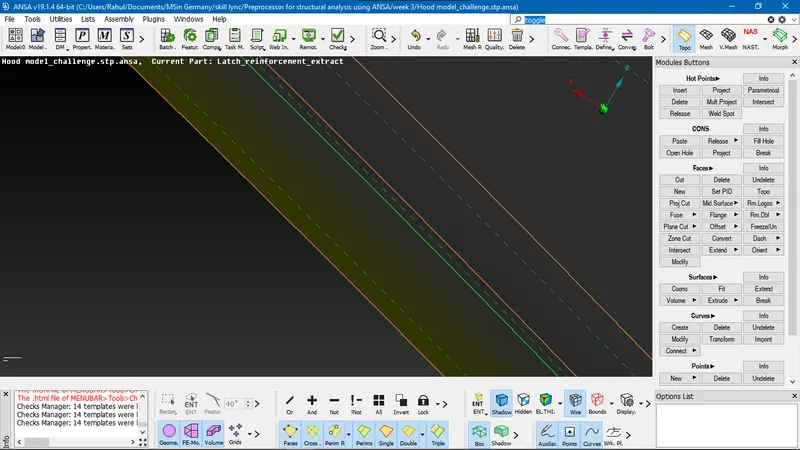
- The image shows the defeatured portion of the hood. It is done by removing the Cons on the top, bottom and middle of the hemmed region by using MESH > Macro > Join option. The deleted cons are represented by orange colour and the retained con is shown by green. This middle con is retained to capture the geometry of the CAD model.
- Similarly defeaturing is performed for max length criteria failure by creating a con using MESH > Macro > Cut option to divide the elements in smaller parts.
- Preparing the surface for meshing
- Again the Geometry checks are performed on the midsurface before meshing
- Meshing is a lengthy process, hence to mesh faster on the symmetric parts, half of the part is deleted from the mirror plane shown in the below image.
- This is done by using Menu bar > Utilities > Delete option. Then the half of the CAD model is selected as entity and deleted with middle mouse button confirmation
- This creates many open faces and the model fails for Geometry checks. The open faces are fixed with TOPO > Faces > New option. The surface type : FITTED is selected.
- Then ANSA prompts for cons selection. The selected Cons define the plane and boundary of the new face.
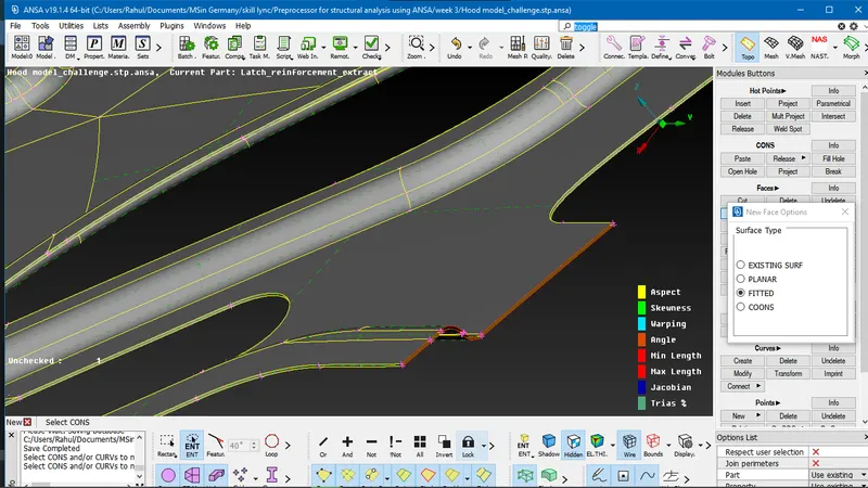
- Meshing:
- Meshing is done for using MESH > Mesh Generation > Best option
- This function creates mesh on the selected entities using the various meshing algorithms and retains the mesh of bets quality.
- In the option list, Reconstruct is selected.
- Manual reconstruction of mesh is done using MESH > Shell Mesh > Reconstruct function
- This is a function that is used to create high quality mesh. This function deals with quality errors and minimizes them by making modification to the underlying CAD surface. The reconstruction is done on the basis of the quality criteria
- Smoothening of the mesh flow is done using MESH > Shell Mesh > Smooth function
- This function relaxes the mesh flow on already meshed macro areas
- All these functions are used to create better mesh
- After meshing is complete, it is mirrored to the other side show the mesh on the whole CAD model
- This is done using Menu Bar > Utilties > Trasform (Copy) fucntion
- This allows the selected entities to be copied to a new location.
- The entities are selected and confirmed. Then the function window appears. Symmetry tab is selected and the Use field is set to Mirror 3 points Plane.
- The three points are selected from the CAD (one from top, bottom and middle part) to define the mirror plane and Apply button is pressed.
- Then the Trasnformation options window appears regarding the newly created entity. The Property ID of the new entity is set to same and Ok is pressed.
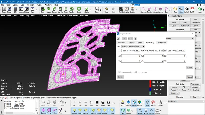
The following image shows the transformed model. The FE and the geometry are mirrored about the centre plane. This avoids duplication of the CAD model.
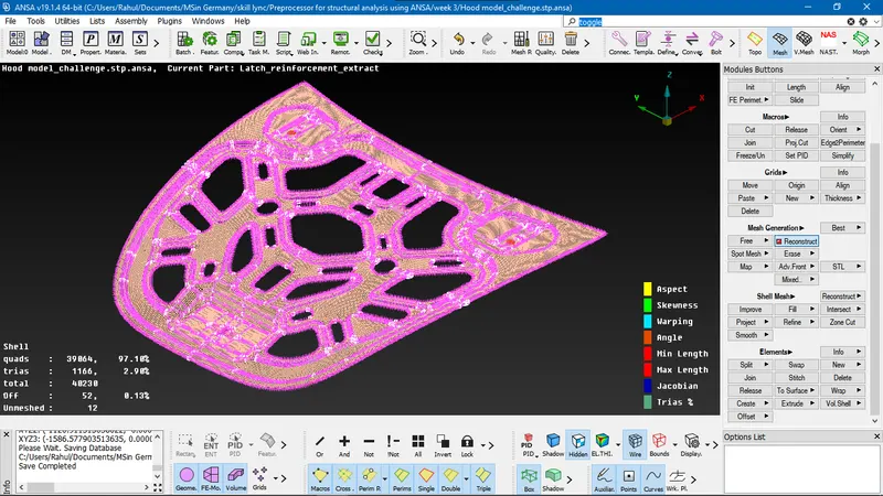
- Release of the FE Model:
- The function is available in MESH > Elements > Release. On selecting this function, all the entities of the midsurface are selected and confirmed.
- This function detaches the mesh elements in the macro areas from the underlying geometry. Hence the CAD model and FE model are separately available. FE model can be viewed using FE-Mod visibility button and turning of Geometry button.
- The FE model PID is the same as the midsurface model.
Learning outcomes:
- When the mesh elements are released from CAD geometry, some of the mesh elements go missing and a gap is created in the FE model. This gap is filled using MESH > Shell Mesh > Fill function. The edges the gap are selected and confirmed to fill the gap as shown below

- In the released FE model, sometimes the adjacent micro areas are not connected. The connected nodes are represented by yellow spots. Automatic connection can be done using MESH > Grids > Paste (Auto), then the visible entities are selected with confirmation and all the nodes within the vicinity of 0.2 mm are pasted together by default.
- Sometimes, the nodes are farther than 0.2 mm and fail to paste. In this case, the distance can be set higher 0.2 mm for auto paste function or manual pasting is done by selecting the adjacent node pairs and setting the parametric position to COG in paste window.
- When the elements in the mesh fail and couldn't be rectified, then create a small macro area around the failed elements by using MESH > Edge2Perimeter function. Then perform MESH > Shell Mesh > Reconstruct function to automatically rectify the poor quality mesh.
- The opposite-facing trias can be eliminated by using paste function. The row of nodes connecting both trias are pasted to COG.
- The trias facing each other are eliminated by using MESH > Elements > Split function and creating another row of mesh.
- The trias at the edge of the surface are eliminated by using Swap function in MESH > Elements and improving the mesh flow using the Smooth function in Shell Mesh under MESH deck.
Conclusion:
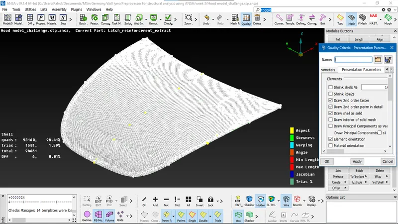
This image shows the final meshed model. As seen above, the trias percentage is 1.59 % that is below the maximum requirement of 15 %. The OFF elements are the mesh elements that fail the quality criteria. The number of OFF elements are 6. On the right side, Draw shell as solid is enabled in Menubar > Utilities > Quality Criteria.