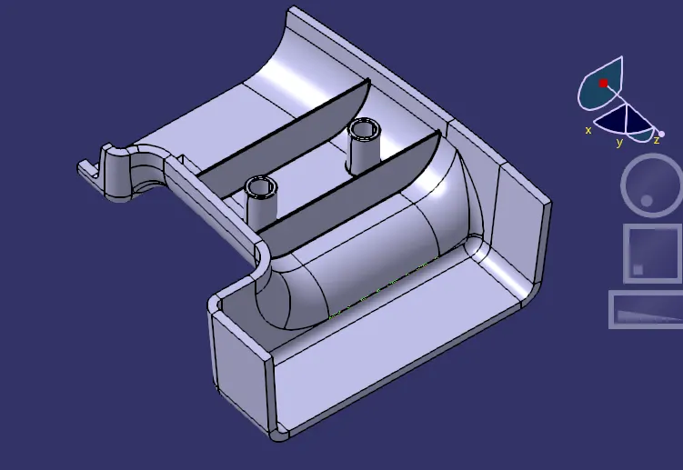
Week 9 - Attachment Feature Creation (Ribs & Screw Boss) - Challenge 1
Introduction:
To create attachment features on the door handle part. The attachment features include ribs and dog houses.
Procedure:
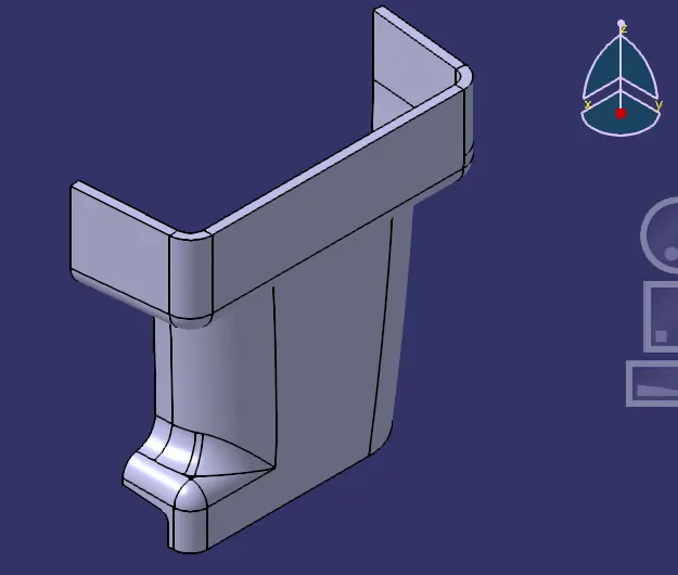
1. The image below shows the Class A surface of the door handle. Cursory look at the part reveals that the tooling axis is along the Y-direction.
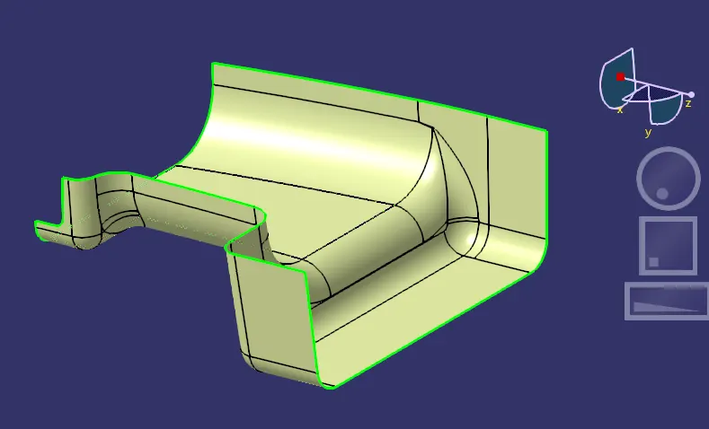
2. Tooling axis is created
- Along Z-direction, all the surfaces are mostly perpendicular to the tooling direction. Hence there are no problematic faces to be cleared in this direction.
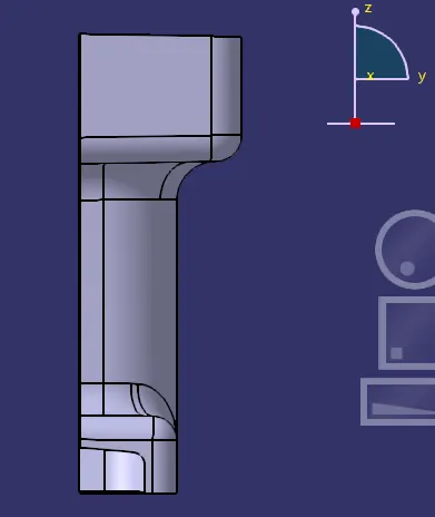
- Along X-direction, there are faces parallel to the tooling direction. Hence they are required to be cleared. The surface profile is created for X-direction by intersecting the Class A surface with the XY plane. Then lines area created to form extensions of the surface profile.
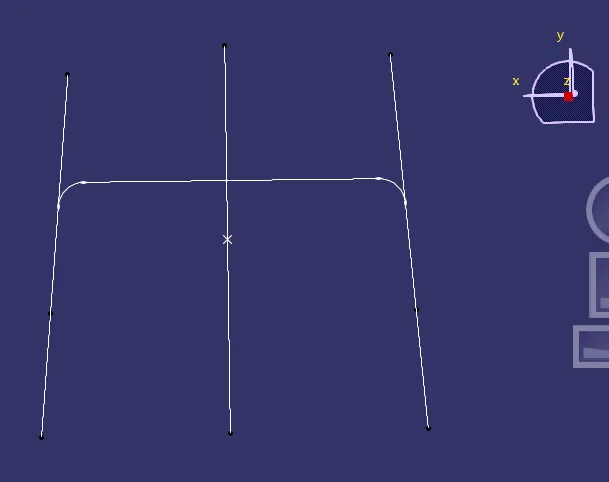
- Bisecting line is created using the Line command and selecting the two extensions. This line represents the tooling axis.
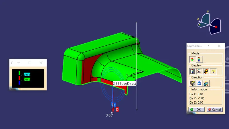
- Draft analysis is created using this tooling axis as reference. The surfaces highlighted in green clear the tooling while the red represent the probelmatic faces. Since the red faces have draft angle 2.99 (slightly lower than the 3 degree required), these surfaces are acceptable.
3. B and C surface creation:
- B surface is created by offsetting the A surface by 2.5 mm using the Offset command.
- C surface is the surface that closed the gap between the A surface and the B surface. It is created by using the Sweep command. A line is created between the a point on the A surface edge and B surface edge. This line serves as a profile. Then Boundary command is used to extract the overall edge of the A surface to serve as the guideline for the Sweep command. Then surface sweep is produced and Join command is used to enclose the Surfaces.
- The complete surface is used to produce solid body in the Part design module.
4. Rib and Screw Boss creation:
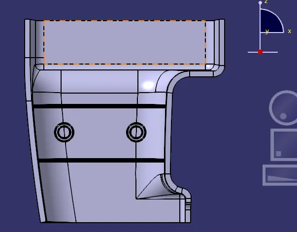
- Bottom surface of the class A surface is selected to form the Rib profile. This profile is extruded by 12.5 mm (<=5*t) and thickened by 1 mm (<=0.4*t). Then draft angle of 0.5 degrees is provided and a fillet of 0.25 mm radius is produced on the rib edges.
- Similarly the bottom surface of Class A is used to create a screw boss profile. Since it is designed for M5 screw, hole diameter is set to 5.2 mm and wall thickness of 1.5 mm (<=0.6*t) is given for the Boss. The sketch is padded to the height of 12.5 mm and draft angle of 0.5 degrees is given for inner and outer wall of Boss. Using Union trim, the bosses are assembled with the Door Handle. Then a filled of 0.25 mm is provide for the bosses.
Conclusion:
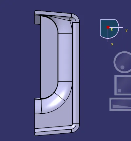
The final view of the door handle is shown below as per required dimensions: