Week 8 - Challenge 1 - Base Bracket Design
Base Bracket Design:
The base bracket design process involves creation of the tooling axis for the given class A surface, performing draft analysis for class A surface, creation of class B and class C surface, trimming all surface together and closing the surface to create solid body.
Tooling axis creation:
- Class A surface is examined from all angles to determine the best tooling axis direction.
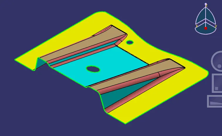
- Due to the presence of holes, the base bracket cannot be parted along X and Y directions. To part it along X or Y direction, required side core in the mould machine to form the holes, which would make the moulding process complicated and expensive. Hence dummy tooling axis is chosen to be Z-axis
- The bracket can be parted along Z-axis, hence in order to create tooling axis, surface profiles along X and Y axis are created using Intersection command
- Z-X plane and Y-Z plane are chosen to intersect with the A-surface and generate surface profiles.
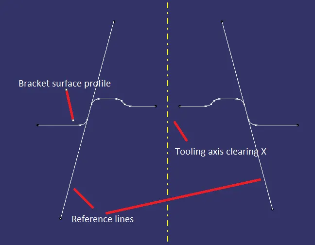
- Two reference lines are created indicating the surfaces that could create a problem while parting. These are the surfaces that are appromately parallel to the Core-Cavity parting direction.
- Using Line command and Bisecting method, a line is created using reference lines (that are to be bidected) and a point (where the new line passes through). This lines represents tooling axis that clears the X profile of bracket
- Similarly tooling axis is created for Y-profile of bracket. Both the tooling axes are used to bisect and form the main tooling axis
Draft analysis:
- Feature draft analysis command is used to perform draft analysis. Compass is selected under Direction pane and global compass in Catia V5 is dragged and dropped on the main tooling axis. Then "Show colour scale" option is turned on to display the draft angles of the various faces of the A-surface
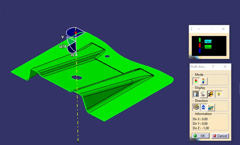
- The colour scale of the A-surface reveales that all the faces of the surface are clearing the min draft angle of 3 degrees.
- Then class B and C surfaces are created and trimmed with A-surface. In Part Design module, Close Surface command is used to create a solid body of bracket.
- Using the same tooling axis and same method of Feature draft analysis, darft analysis is performed on the solid body of base bracket
Conclusion:
The darft analysis result for Base Bracket solid body is shown below:
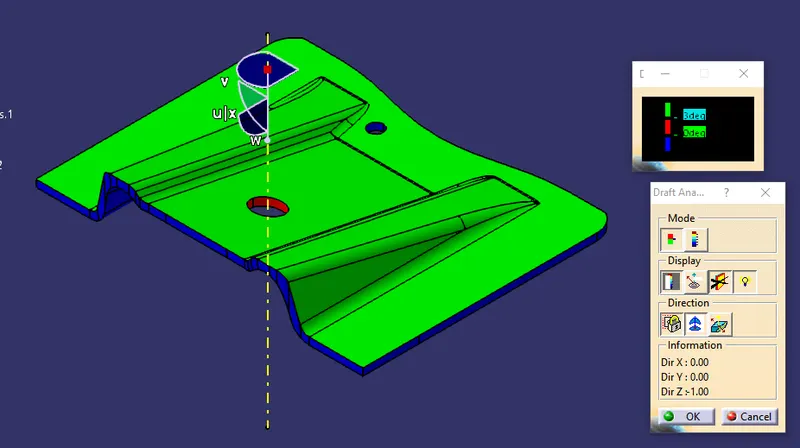
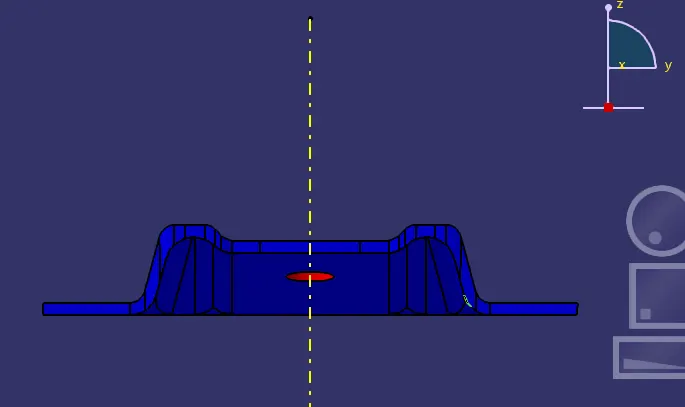
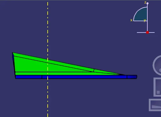
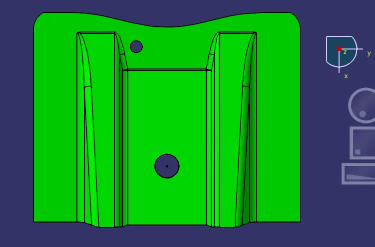
Hence all the top faces of the bracket clear the draft requirement.