Advanced Sheet Metal Design Using NX Cad Challenge_5_Odd Shaped Enclosure
Title:
Design of Sheet Metal Odd Shaped Enclosure in Siemens NX
Objective:
- Modelling the enclosure as a solid component to generate a general enclosure layout
- Converting the solid to sheet metal and adding required features to the unbend version of the enclosure in Sheet Metal application
- Drafting the 2D engineering drawing of the flattened sheet metal
Introduction:
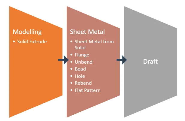
Siemens NX has various applications to design the required model. Solid can be generated in the Modelling application and the same solid can be converted to sheet metal in the Sheet Metal application. This conversion can be done using the Convert to Sheet Metal wizard which consists of the following sequential process:
- Edge Rip
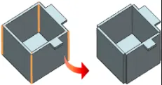
- This is the first step followed by the wizard.
- This action rips the selected edges which disconnects the faces connected by the edge and form 2 different sheet metal entities across the edge.
- The ripped edges cannot be bent
- Cleanup Utility
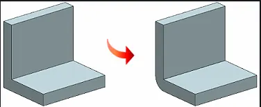
- This command identifies the regions in the model that do not have the characteristics of the sheet metal as given below
- Non-uniform thickness regions that vary more than 10 % of the thickness of the selected face. The command then corrects the thickness of these faulty faces and makes them uniform
- Non-concentric bend regions. The inner bend region may not be concentric with outer bend region. In this case, the command corrects the bend radius to make them concentric
- Silver faces. These are the faces with one dimension significantly higher than the other two dimensions, i.e, length highly greater than the width of the face. These faces are eliminated.
- Spike faces
- Non-continuity between the planar face and adjacent bent face is also identified and made to have continuity.
- Bends with zero inner bend radius are recognized and bend radius is increased to meet the global value
- Sharp edges remaining after edge rip are also identified and a minimum bend radius of 0.02 mm is applied
- Optimize Face
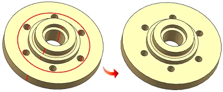
- This command simplifies the surface types, merges faces, improves edge accuracy and recognizes blends.
- Convert to Sheet Metal
- This command changes the definition or configuration of the model from anything to Sheet metal and allows the user to perform sheet metal operation
- This command initially follows global conversion that converts the whole body to sheet metal and then the regions that remain unaffected after global conversion are treated with local conversion to individually convert to sheet metal form.
Design Approach:
Description:
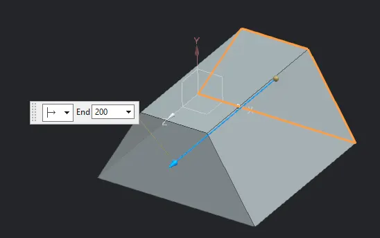
- Extrude
- Trapezoidal profile is created on XY plane and extruded along the Z direction for 200 mm
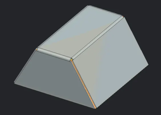
- Sheet Metal from Solid
- In this the connected web faces are selected. The edges of the selected faces are automatically converted to bend feature.
- The web faces that are having edges shared with multiple selected web faces form conflict. NX does not know which edges are to be converted to bend feature and which edges are to be ripped. Thus Select Bent Edge parameter pops under Parameters section. The bent edge connected with top face is selected.
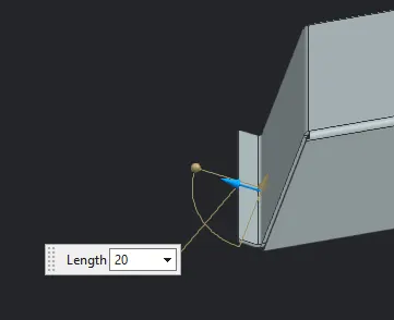
- Flange
- Outer edge of the side face is selected to form flange.
- Length of the flange is set to 20 mm which includes the web length and inner bend radius
- The other parameters are set to global value of 3 mm
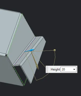
- Jog
- This command creates an elevation in the specified region of the sheet metal. This area is based on the sketch profile that is on either side of the profile.
- The elevation is set to 20 mm
- The height reference is set to inside which means that height includes the inner bend radius but excludes the outer bend radius of base face.
- The angle is set to 79 degrees
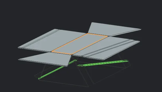
- Unbend
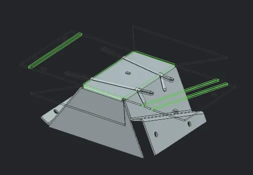
- The top face is selected as stationary face and bend regions are selected to unfold and flatten the sheet metal.
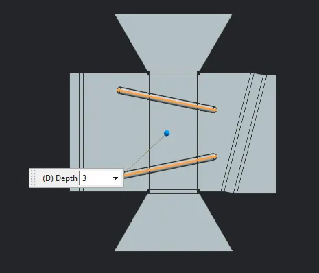
- Bead
- Bead is created to stiffen the sheet metal.
- The height of the bead is set to 3 mm
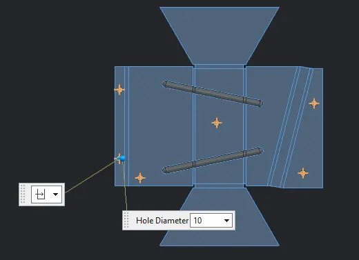
- Hole
- Hole regions are specified on the flattened sheet metal by creating points at various positions
- Hole type is set to Simple
- Hole size is set to custom and diamter is set to 10 mm
- The holes are created through the body and are normal to face
- Rebend
- All the bend regions are selected to bend back to the original form
- Flat Pattern
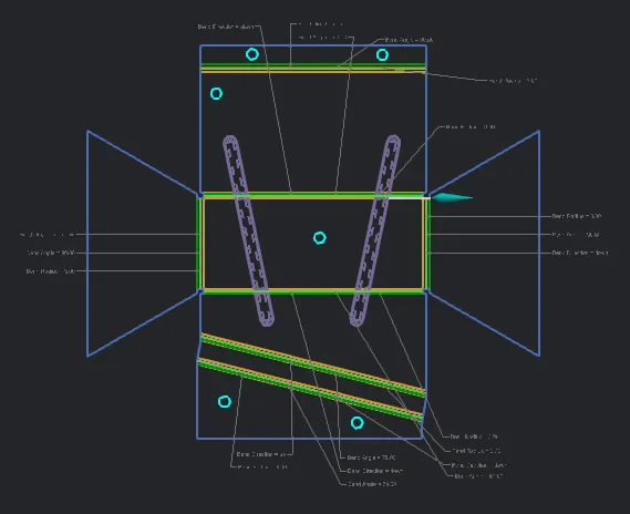
- Flat pattern is generated by selecting the top face.
- This generates 2D version of the model and also specifies the parameter details like bend radius
Conclusion
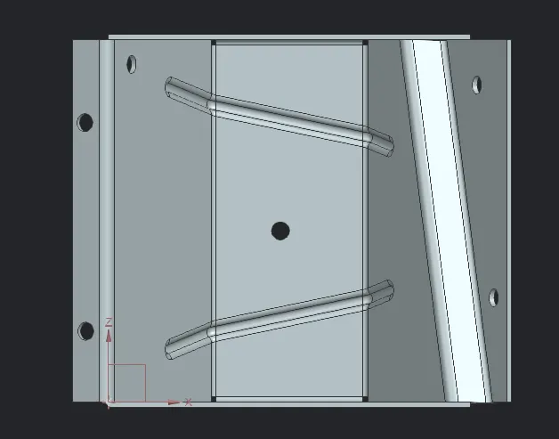
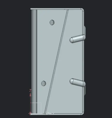
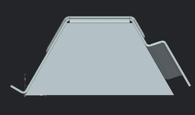
The odd shaped solid model was converted to valid sheet metal using appropriate commands. All the side faces connecting to the top face are having bends which are replaced with edges. The edge rip is automatically performed on the edges that are connecting side faces of the model. The bottom face automatically gets deleted after Sheet Metal from Solid operation and the material filling the space within the outer faces is removed and replaced with the global thickness value of 3 mm. The Jog feature couldn't be created perpendicular to the base face, hence inclination of 79 degree was provided. The model was created with good accuracy and the following images display various views of the model:
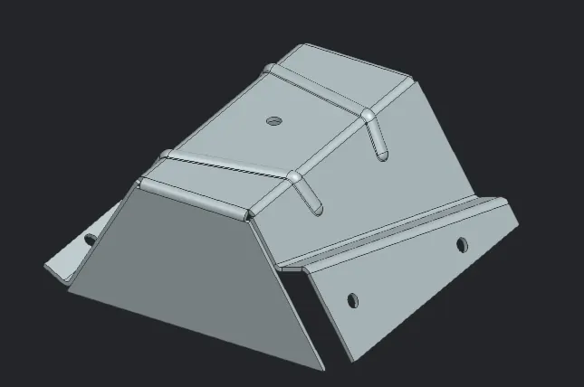
Isometric View:
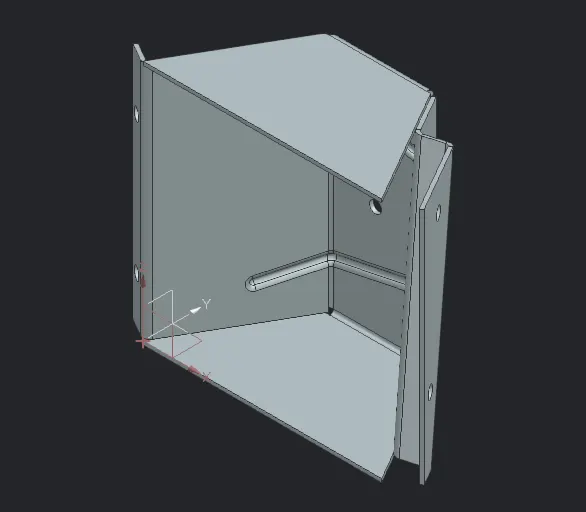
Front View:
Right View:
Top View:
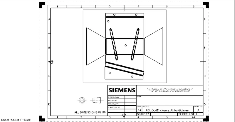
Draft: