Week 8 - Challenge 4 - Bumper
Draft Analysis of an Automotive Bumper Plastic Component:
Introduction:
A bumper is an automobile's front part that shields the engine and provides housing for headlamps and defogging lamps. It is a plastic component and is manufactured by Injection Moulding Machine. Hence the component needs to be verified if it can be smoothly extracted from the moulding machine. In order to check this, a draft analysis is performed on the CAD of the bumper in Catia V5 using Feature Draft Analysis command. This ensures that no face of the component is parallel with the mould axis.
Draft Analysis Procedure:
- The component is rotated and checked for probable tooling axis.
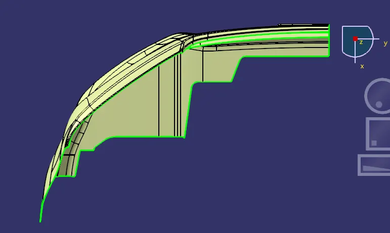
- The component cannot be parted in Z-direction. Since the part has pocket to house headlamp, side-core will be required which would make the moulding process complicated and expensive.
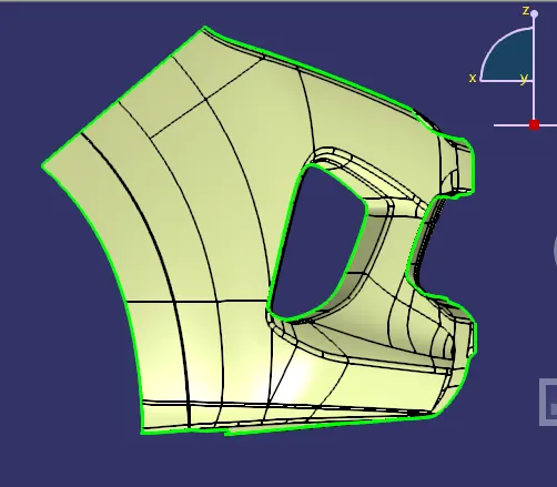
- Due to the above stated reason, component cannot be parted in Y-direction also
- Hence X-axis is preferred as dummy tooling axis
- Tooling axis generation:
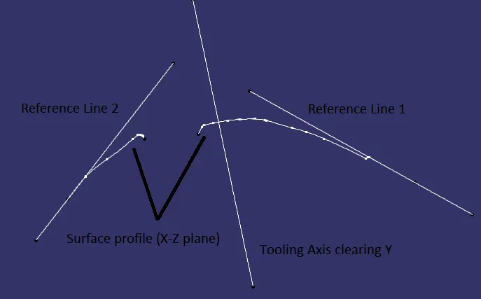
- Using Intersection command, surface profile is generated by selecting Class A surface and X-Z plane
- Using Line command in point-point selection method, reference lines are generated.
- Bisecting option is used in Line command to generated tooling axis clearing Y direction.
- The same procedure is followed for Y-Z surface profile to obtain X-direction clearing tooling axis
- Both the tooling axes clearing orthogonal surface profiles are selected to generate main tooling axis using Bisecting option in Line command.
- This tooling axis is used to perform draft analysis for Bumper. This axis represents the direction along with Core and Cavity would disengage to eject bumper from the mould.
- So Feature Draft Analysis command is used to verify the inclinations of all the faces of the Bumper with respect to Tooling axis.
- Before the analysis, Bumper is set to material mode in Custom View Parameter.
- Within Draft Analysis command, Compass is selected and UVW axis system is dragged and dropped onto the tooling axis.
- On selecting the bumper, it highlights the faces of bumper. Green indicates that a face has a draft angle greater than 3 degrees. The following result is obtained:
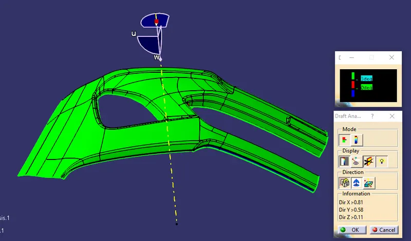
- All the top faces of the bumper clear the draft angle requirement.
Draft analysis of the final model:
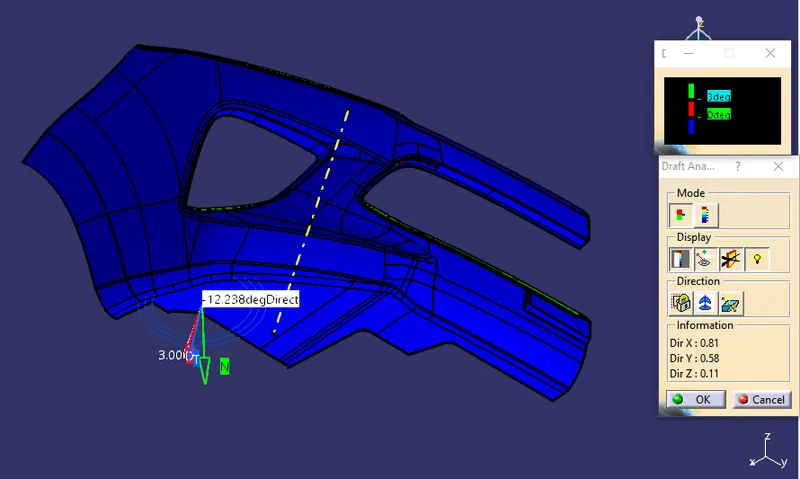
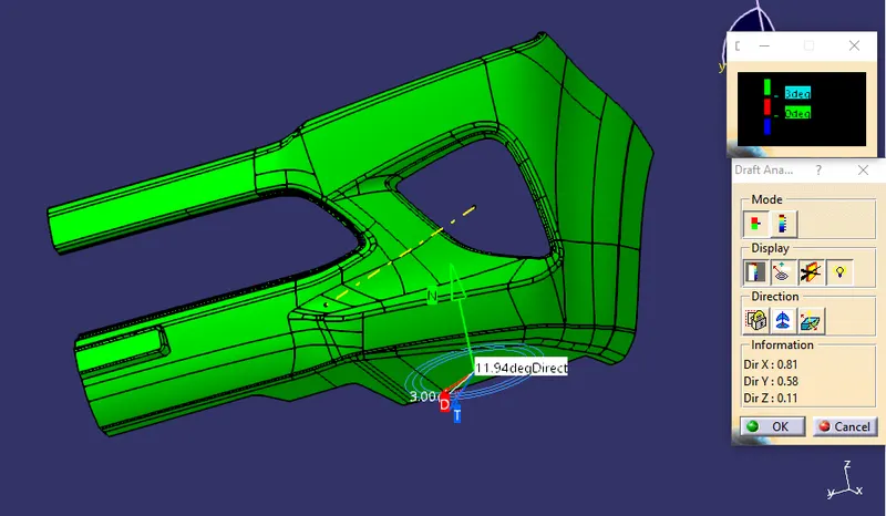
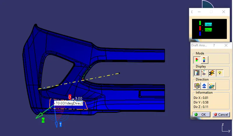
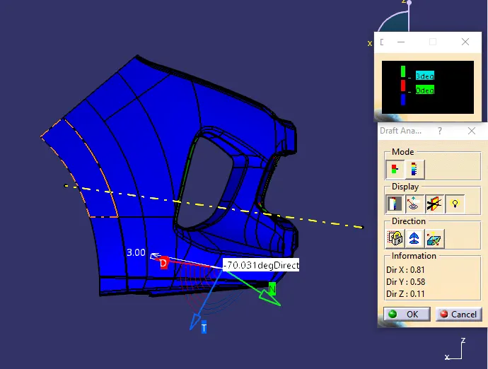 '
'
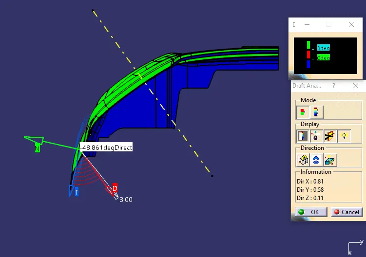
Hence the images indicate that the model has cleared the draft angle requirements.