Week 9 - Project 1 - Door Trim Lower with Engineering Features
Introduction:
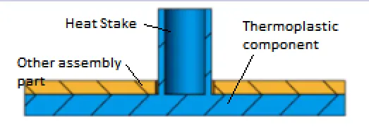
When thermoplastic components are involved in the assembly, they are required to be joined with a dissimilar material. The material with which it is assembled could be a metal or a other kind of thermoplastic material. The joining is facilitated by heat staking. Thermal staking is an assembly process which involves controlled melting and reforming of a plastic stud or boss to lock thermoplastic component with other part. The heated thermal tip contacts, melts the top of the stud or boss, and fills the tip cavity to produce a head, which locks the component in place. The melting of the stud with continuous application of pressure form the head which locks the engaging component with the thermoplastic component.
The advantages of heat stacking are:
- Simplification of machinery
- Reduced cost of machinery
- Multiple fastening points
- Allows higher density of welds compared to hot air cold form or ultrasonic welding
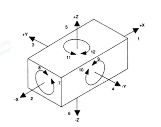
During the assembly process, various parts are engaged with each other. Initially, any part has 12 degrees of freedom. But these degrees of freedom are curbed during the assembly process. The degrees of freedom are: Translation along X, Y and Z axes and rotation about the same axes. It is demonstrated in the picture below:
Aim of the challenge is to create heat stakes and locator pins on the B-side of the Door Applique model. Door applique is a styling surface which is attached to the door frame. Class A surface taken as an input based on which Class B and C surfaces are created. Draft analysis is done by creating Tooling Axis for Class-A surface and verifying the draft angle for the whole model. Heat stakes are created on the Class-B surface side over the points indicated in the image shown below:
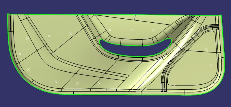
The function of the locator pin is to engage one part with the other. Two locator pins are created on the current model. These pins are projected out of the Class B surface along Y axis. Thus these pins restrict the following degrees of freedom:
- Translation along X and Y
- Rotation about the Y axis
Procedure:
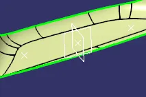
- Planes are created paralled to XY and YZ on one of the heat stake point. The same planes are used to intersect with the Class-A surface to generate the outline.
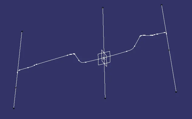
- The intersection along the XY plane is considered. The outer lines representing the outer wall of the door applique are close to vertical, hence are considered for draft analysis. Lines are created as an extension of these outer lines and an axis is created to clear Z-axis tooling. The axis is created using Line command with Bisecting option. The side lines are taken as input and mid-point is selected through which axis should pass.
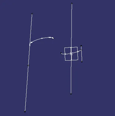
- A similar process is followed for the intersection along YZ plane. This gives another tooling axis that clears along X-direction.
- Finally bisecting method is used again to clear Main tooling axis by bisecting the tooling axes clearing Z and X direction.
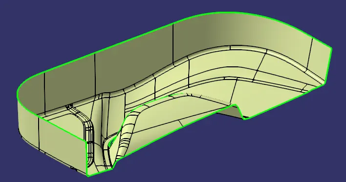
- Class B surface is formed using Offset command in the Generative Shape Design module with offset distance of 2.5 mm. Few fillet regions with smaller radii are unformed and gaps are generated. These surfaces are fixed using the Fill Surface and Multisection command to obtain Class B surface replicating the Class a surface as shown above.
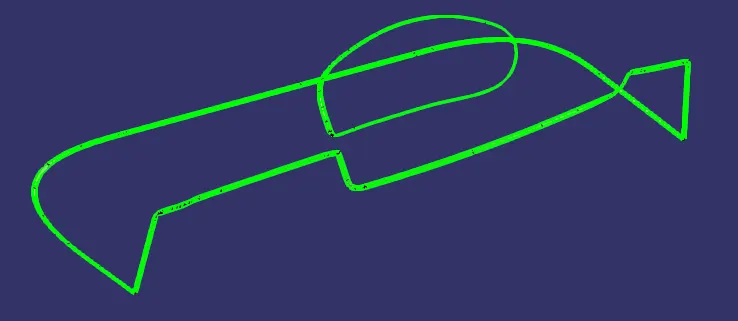
- Class C surface is formed using the Sweep command with the Reference Surface option. Class A surface is taken as a reference. The outer boundary of the Class A surface is extracted using Boundary command and taken as Guide curve for Sweep. The angle is set to 93 degrees to include a draft of 3 degrees for Class C surface.
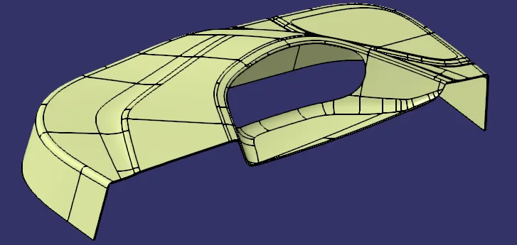
- Final surface model is created by joining class A and Class C surface using Join command. Then Class B surface is extrapolated for 2 to 3 mm to extend it beyond the Class C surface. Thereafter Trim command is used to remove the extra surface and join all three surfaces together.
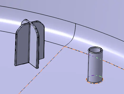
- Heat stakes and locator pins are created as per the requirement.
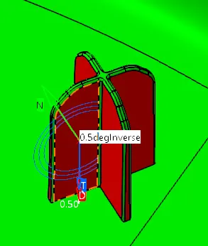
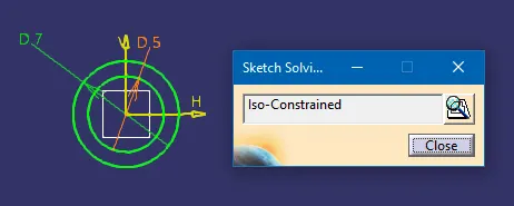
- Heat stake is formed with Pad command. A sketch is created as shown below and used for padding. Then it is drafted for 0.5 degrees and a fillet of 0.3 mm is provided. The same heat stake is pasted with link for all the points where a heat stake is required. This copied body is translated to various positions using Point-Point Translation.
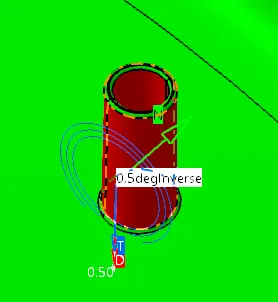
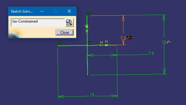
- The locator pin sketch (shown below) is padded with thicken option for 1.3 mm about the neutral fibre. The vertical faces are drafted for 0.5 degrees. Chamfer of 3 mm and 45 degrees is provided for the top edges and filleted for 3 mm. Other edges are filleted for 0.3 mm. The same locator pin body is copied and pasted with link and translated to other position.
- The locator and heat stake bodies are assembled and joined with the Door Applique body using Union Trim command.
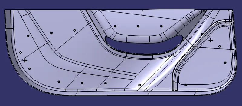
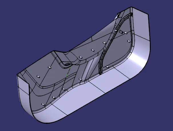
Final model:
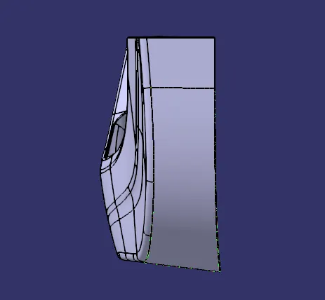
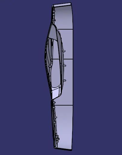
Draft Analysis:
The draft analysis is performed with Feature Draft Analysis command. In the Custom View Parameters, the view mode is set to Material. After activating the draft command, the compass is set on the Main Tooling axis and locked in the position. The green colour indicates draft angle > 3 degrees; Red colour indicates angle in the range of 0 - 3 degrees; and blue indicates a negative draft angle.
Class B surface:
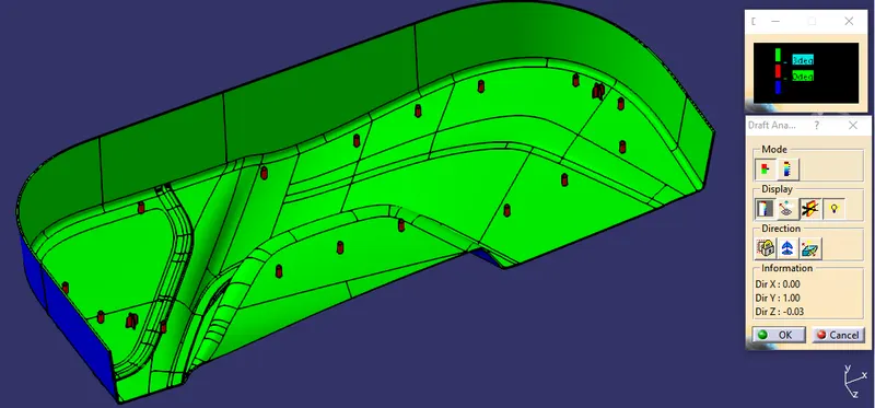
As seen, the majority of the class B surface clears the draft requirement of 3 degrees.
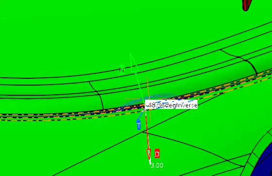
Small fillet region has a negative draft angle.
Class A and C surface:
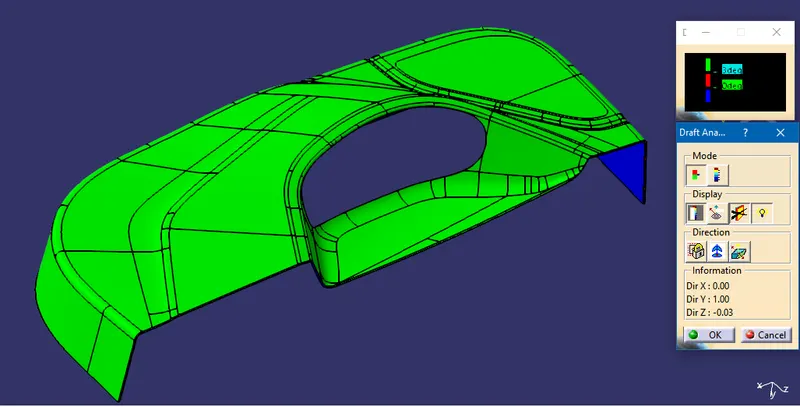
Class A surface clears and is acceptable.
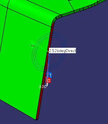
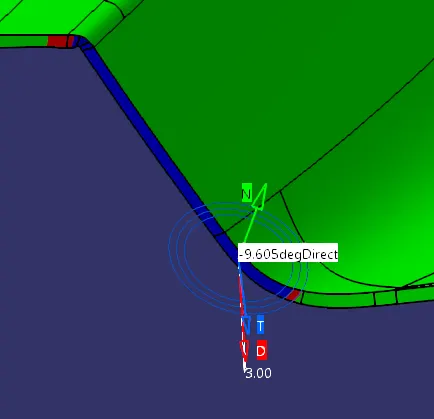
The above images show the Class C surface where it is failing. The red region is short of 0.5 degrees to clear and the blue region has negative draft that is unacceptable.
Heat Stake and Locator Pin:
The green region is set to 0.5 degrees. Since 0.5 degrees is sufficient for B-side features.
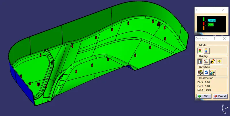
All the heat stake and locator pins are in Green/Red region. All the surfaces have a minimum draft of 0.5 degrees.