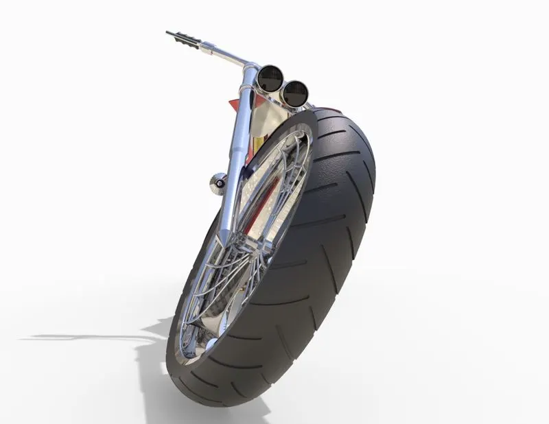
Modelling of American chopper in SolidWorks using bottom-up approach, assembling all the parts using appropriate mate conditions and rendering photo-realistic images of the two-wheeler using SolidWorks Visualize.
Title of the Project:
Modelling of American chopper in SolidWorks using bottom-up approach, assembling all the parts using appropriate mate conditions and rendering photo-realistic images of the two-wheeler using SolidWorks Visualize.
Objective:
- Modelling all the parts of the American chopper in SolidWorks parts file: Front wheel, rear wheel, front fork, chassis, fuel tank, oil tank, foot pedal, kickstand, engine, front fender and rear fender. 2D sketches are drawn on the planes and are converted into 3D models using various features.
- Applying suitable appearances to the models using different materials such as paint, steel, rubber and applying decals on fuel tank, oil tank and rear fender for styling purpose.
- Importing all the parts into SolidWorks Assembly file and applying suitable mate conditions to all the parts and achieving fully defined assembly.
- Adding camera view and editing the latitude and longitude of the camera, depth of field and camera lens to get a better viewpoint of the two-wheeler.
- Editing the scene and applying appropriate environment and backplate and tweaking other parameters for a better view of the American Chopper
- Importing Chopper parts and assembly files into SolidWorks Visualize. Changing the appearance, environment and backplate to obtain a scenic outdoor view of the American chopper and rendering the image.
Introduction:
SolidWorks is computer-aided design software that lets the user produce detailed mechanical drawings and model the 3D parts. The parts are the basic building blocks in SolidWorks and can be put together to form sub-assemblies and assemblies.
Design Process:
- Identify the model requirements: The end result: Americal chopper is fragmented into multiple parts. The required parts are identified. The dimensions of the various parts are finalized.
- Conceptualize the model based on the needs. The styling requirement and the size requirement is considered to conceptualize the model. During this phase, the design approach to develop the model is decided.
- Develop the model based on concepts: The concepts are used to model the parts in CAD software
- Analyse the model: All the dimensions of the model are reviewed
- Prototype the model
- Construct the model
- Edit the model: The model is edited if it does not fit well with other components in the assembly
Design Intent:
The design intent is defined as the reaction of the model to the changes made to the model. Design intent reduces the redesign efforts significantly. The design intent is a concept that the model adapts automatically to the changes made to it. Hence the modelling needs to be done consciously. The design intent is implemented in the model by using appropriate relations in the sketched and appropriate mates in the assembly.
An example of the maintaining design intent in this project is to mate the parts of Chopper with the chassis and not with the global planes so that if the chassis is moved all the parts mounted on the chassis move along with it.
Design method:
The design method is about planning out an approach or methodology to create the models. This includes:
Sketches: These are the 2D drawings, mostly profiles for surface or cross-sections. The dimensions for the part and relations are determined.
Features: These are the tools to convert sketches into 3D parts or solid models. The appropriate tools are selected and the order of application is determined.
Assembly: The components are imported and the type of mate, as well as the components to be mated, are determined.
Photorealistic rendering:
Photorealistic Rendering is an efficient way of creating a photograph of an object that is close to reality. These are the images that are visually more life-like
Design Approach of parts and assembly:
Front Fender:
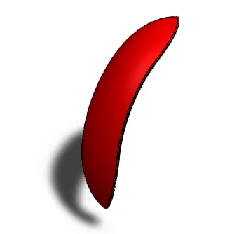
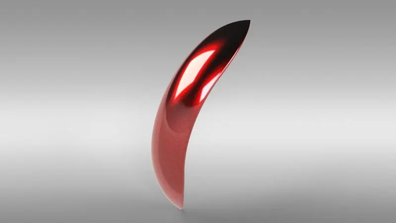
A fender is a rigid part that frames the wheel. The purpose of the fender is to prevent the mud, sand, gravel and liquid particles from being ejected into the air by high-velocity wheel. The particles on the road get temporarily embedded into the tyre threads. The tyre rotating at high velocity imparts kinetic energy to the stuck particles which then eject into the air. The fender acts as a shield and deviates the particles back to the ground
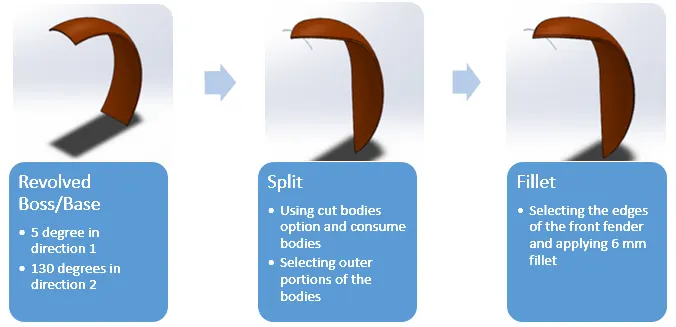
The design approach of front fender in SolidWorks is explained below:
Description of the features:
- Revolved Boss: This feature is used to add material by revolving the sketch around a centerline
- Split: This feature divides the body into multiple parts using the trimming tools geometry. The consume bodies option removes the selected divided material.
- Fillet: This feature is used to create a rounded face. It converts sharp edges into a smooth curve face.
Modelled part image:
Rendered part image:
Rear fender:
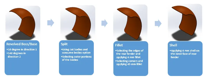
Description of features:
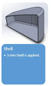
- Shell: This feature hollows out a solid part if nothing is selected and leaves open the face if a face is selected and creates a thin-walled feature on remaining faces
Modelled part image:
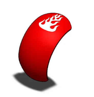
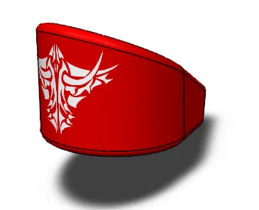
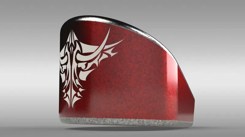
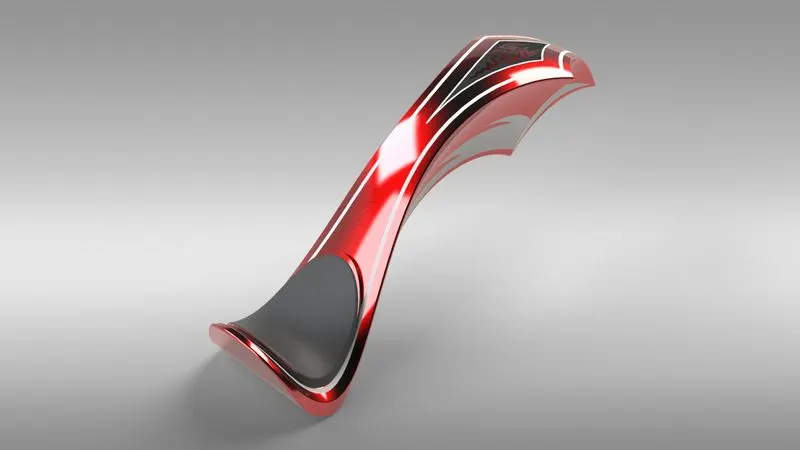
Candy red metallic paint is applied and Decal is applied
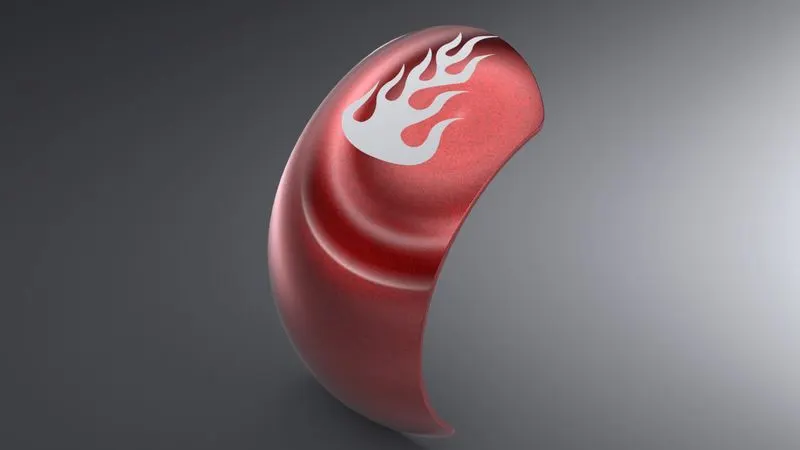
Rendered part image:
Transmission belt:
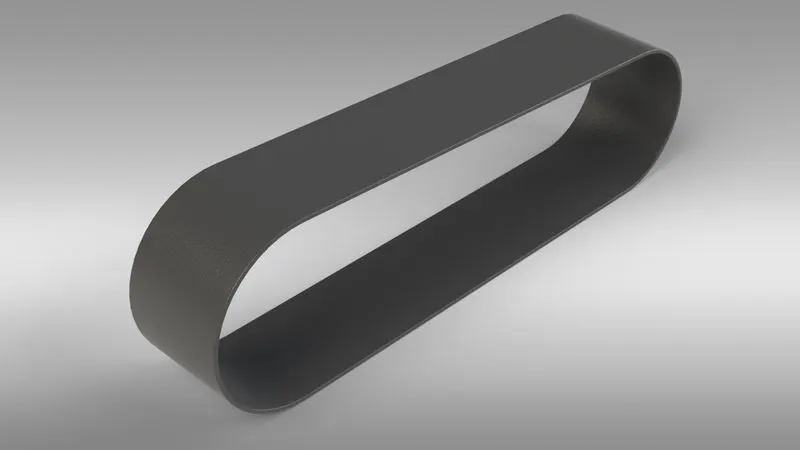
This part is essential for transmitting the kinetic energy produced by the engine to the engine sprocket. This belt is positioned over the pulleys with external teeth. The internal teeth of the belt engage with the teeth over pulleys to transmit the power.
The following features were used to design the belt:
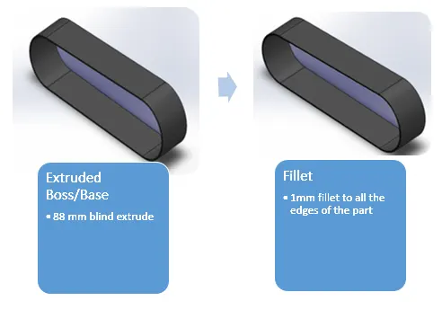
Description:
- Extruded Boss: This feature adds material in the linear direction defined by the sketch
Modelled belt image:
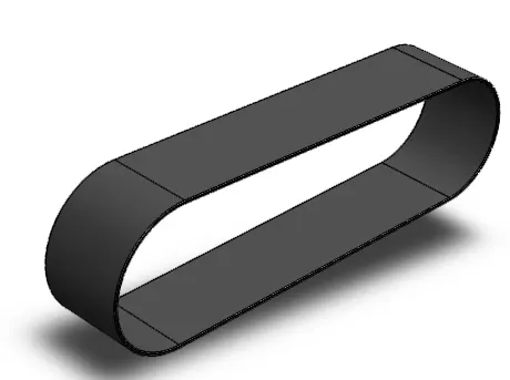
Appearance: Matte black rubber appearance is added to the part
Rendered image:
Foot pedal:
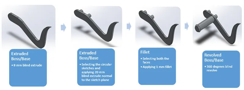
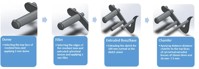
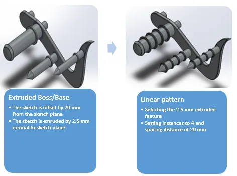
This part mimics the footrest or pedal. This part is used to rest the foot of the rider. The following approach is followed to design the part:
Description:
- Dome: This creates a dome feature on the selected face. Dome is used to convert plane face into convex shape
- Chamfer: This creates a bevelled feature on the selected edge or face
- Linear pattern: This feature is used to create multiple instances of selected features in a linear direction with uniform spacing between the instances.
Modelled part image:
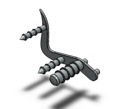
Appearance:
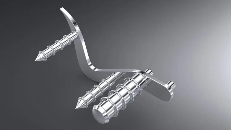
Chrome metal look is added to the part
Rendered part image:
Kickstand:
This part is used to support the two-wheeler on the ground for parking purpose. The upper part is connected to the vehicle chassis and the flat bottom surface is supposed to touch the ground. This part has a limited rotational degree of freedom to be deployed by the rider for parking and to retract it back while riding.
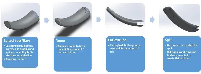
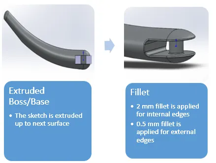
- Lofted Boss: The loft feature is used to create a body that transitions from one profile to another profile. This tool is useful when the body needs to be extruded but not in the linear direction or when the body needs to have different shapes at the end faces.
Modelled part image:
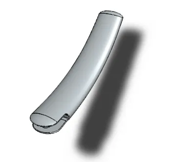
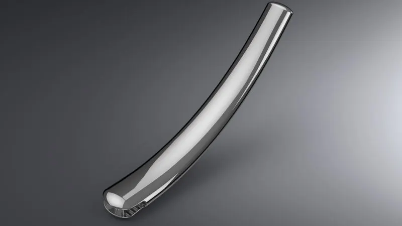
Appearance: Chrome
Rendered part image:
Oil Tank:
This part is a container to store lubricant to be supplied to the engine. The following steps are taken to design the part:
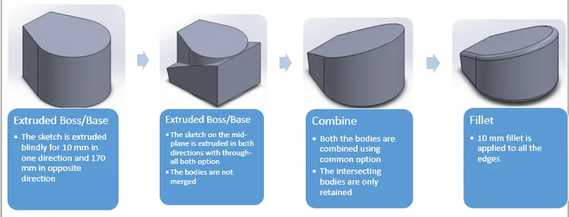
- Combine: This feature is used to combine the part that is having multiple bodies into a single-bodied part. When the common option is selected, the combine feature only keeps the body portion that is common to selected bodies and deletes the rest.
The modelled part:
The rendered part:
Chain:
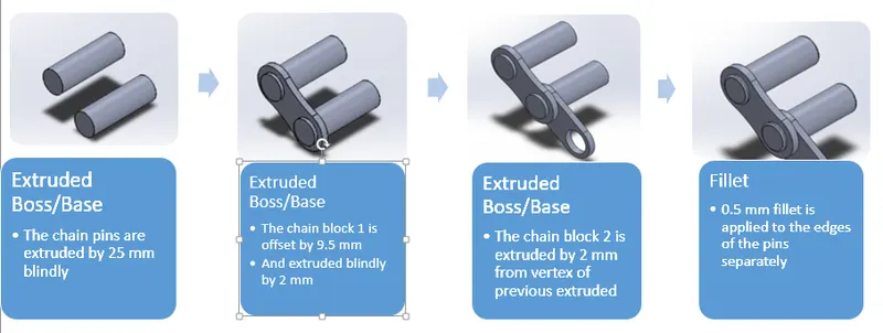
This part is designed to transmit the power from the engine to the rear wheel. The chain fits between the teeth on the periphery of the pocket. Chain is modelled as follows:
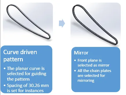
- Curve driven pattern: This feature is used to create multiple instances of selected features along a curve
Modelled part:
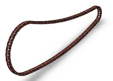
Appearance: Copper
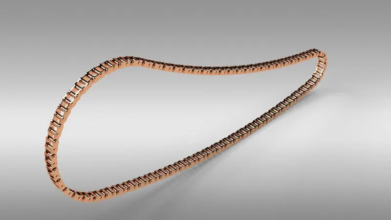
Rendered part image:
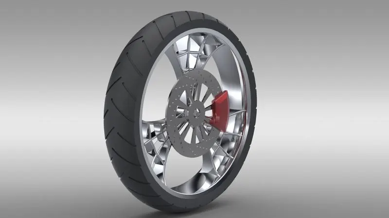
Front-wheel:
This part consists of multiple parts such as brake calliper, brake disc, rim and tyre. This part is designed with the following approach:
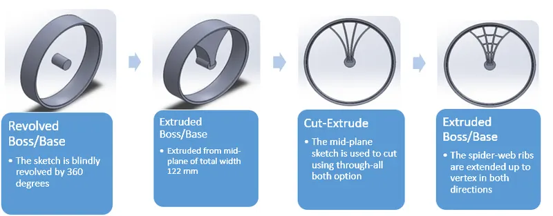
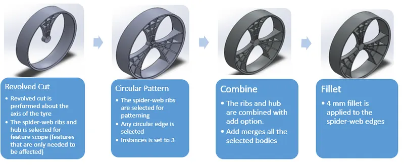
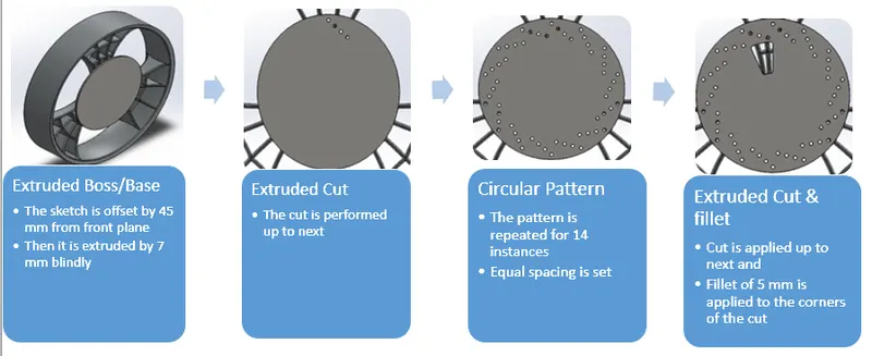
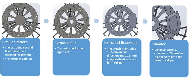
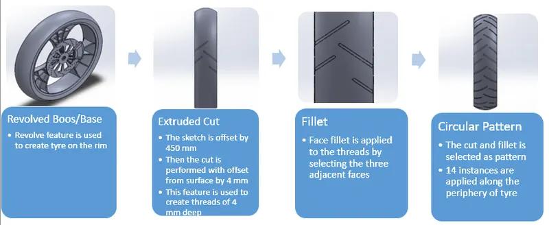
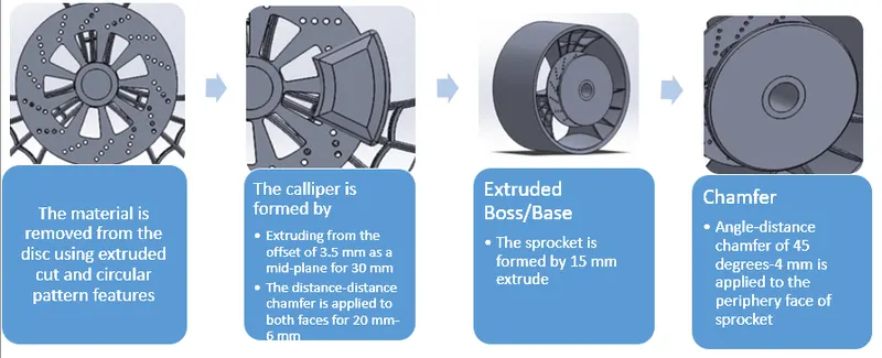
- Circular pattern: This method is used to create multiple instances of the selected feature along a circle. When a circle is selected for patterning reference, an imaginary circle is drawn through the centroid of the selected feature that is concentric to the selected circle. The instances are created along this imaginary circle where features are set apart by an equal distance.
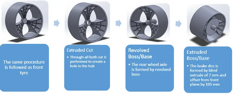
- Extruded cut: This feature is used to remove material in a linear direction from a single body or all the intersecting bodies.
Modelled part:
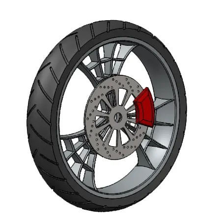
Appearance: Matte rubber is applied to the tyre portion. Chrome is applied to the rim. Candy red metallic paint is applied to the calliper and Carbo steel is applied to the brake disc
Rendered image:
Rear tyre:
Design methodology:
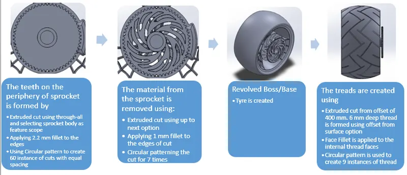
Modelled part:
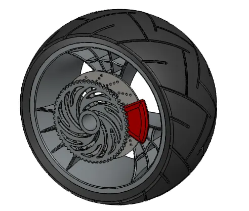
Appearance: Matte rubber is applied to the tyre section. Candy red metallic paint is applied to the calliper. Carbon steel is applied to the brake disc and chrome is applied to the sprocket and rim.
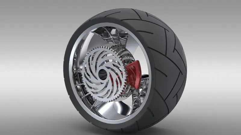
Rendered part image:
Fork handle:
This part connects the front tyre and chassis. It provides the axle for the wheel to rotate about. It consists of headlamps, brake and clutch lever and handle for the rider to steer the vehicle. The following tools were used to model this part:
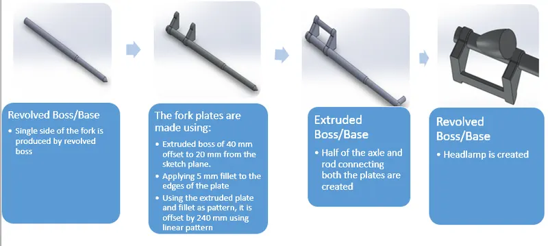
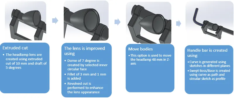
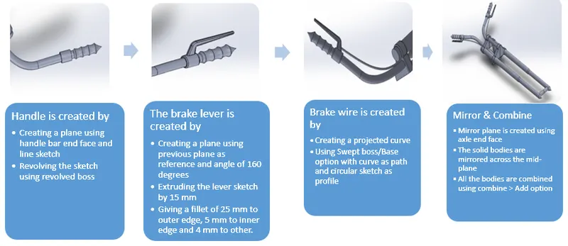
- Move/Copy bodies: This function is used to move the body in a specified direction.
- Projected curve: Projected curve is a representation of intersecting surfaces created by extruded surface feature using sketches in different planes.
- Swept Boss: Sweep feature is used to create a body or add material by moving a profile along a defined path. This feature creates series of multiple sections made by replicating the profile along the path and merging them into a solid body.
- Mirror: This feature is used to create a copy of selected entities about a face or plane. This creates symmetrically opposite entities.
Modelled part:
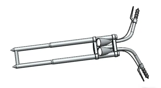
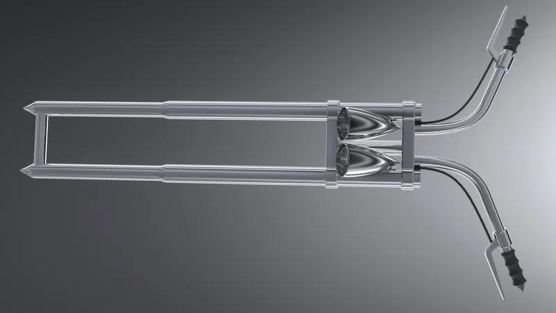
Appearance: Chrome is applied to the overall part. Matte rubber is applied to the handle grip. Glossy rubber is applied to the wire and arena light / clear glass is applied to the headlamp internal face.
Rendered part:
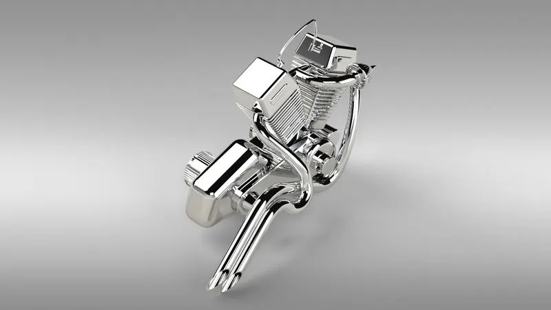
Engine:
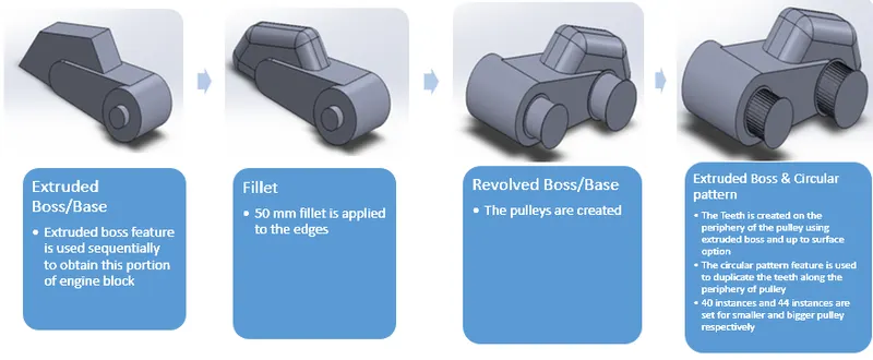
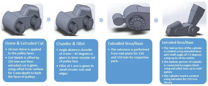
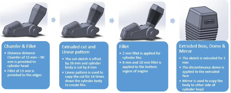
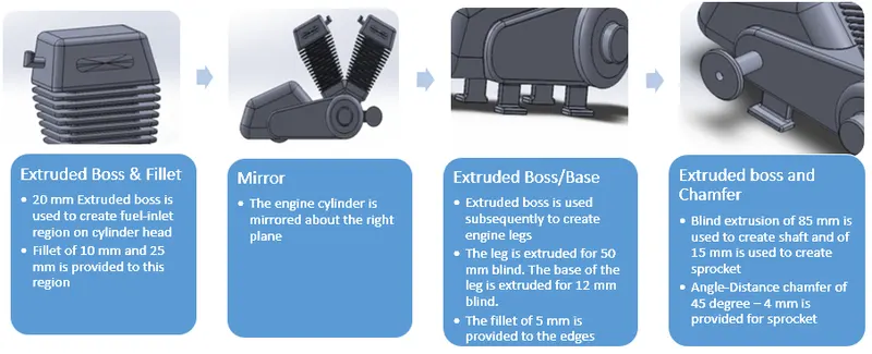
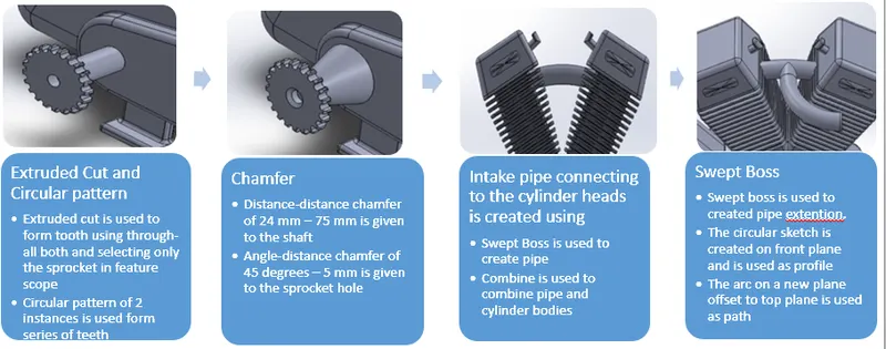
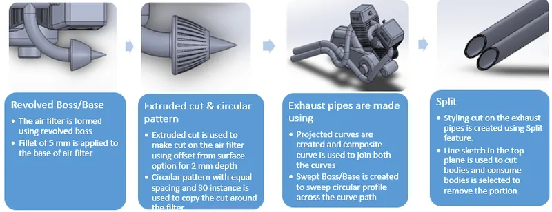
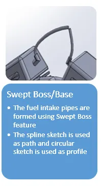
This part is the prime mover of the vehicle. It converts chemical energy into kinetic energy. It consists of two cylinders, crankcase, intake manifold, exhaust manifold, air filter, fuel port, pulleys, sprocket.
The following features were used to design the engine:
Modelled part image:
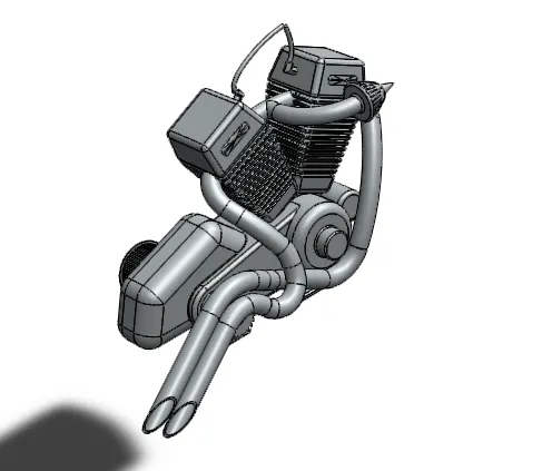
Appearance: Chrome
Rendered image:
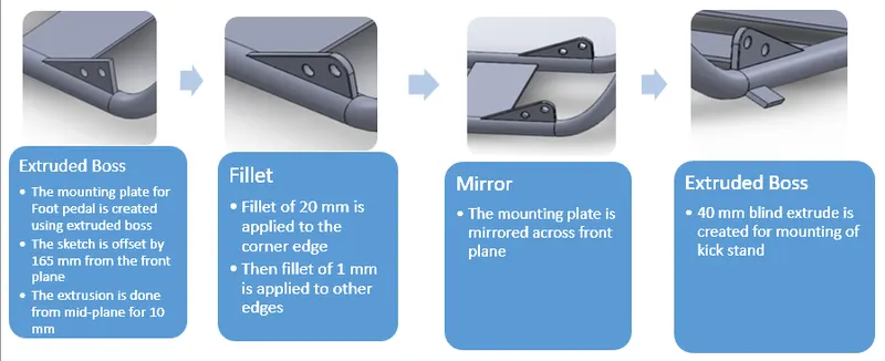
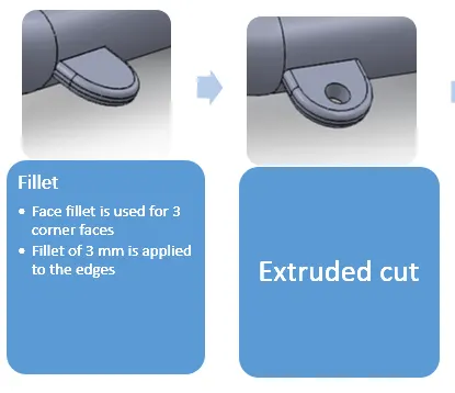
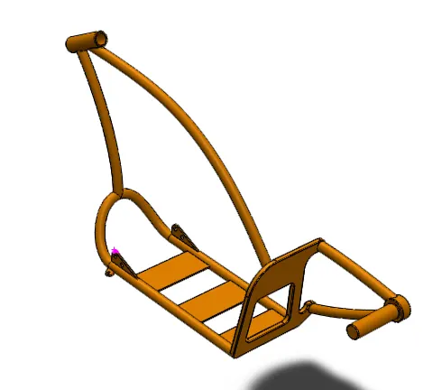
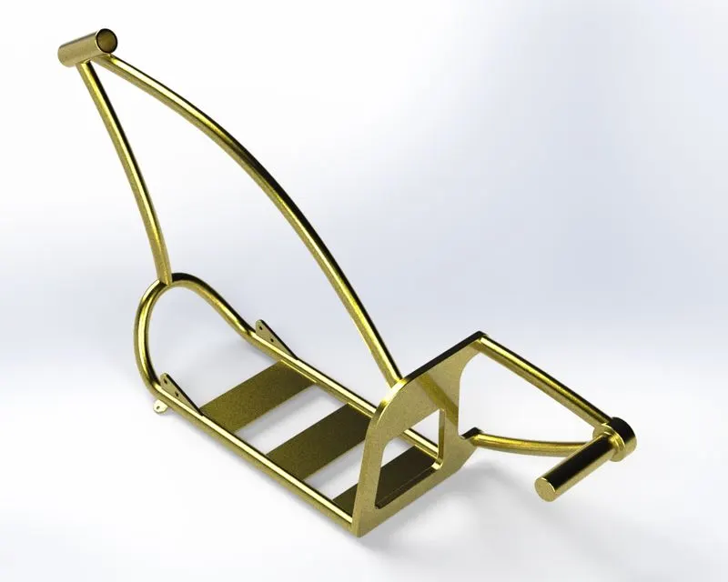
Chassis:
This part is the frame of the vehicle and supports all other subsystems. The design approach is explained below:
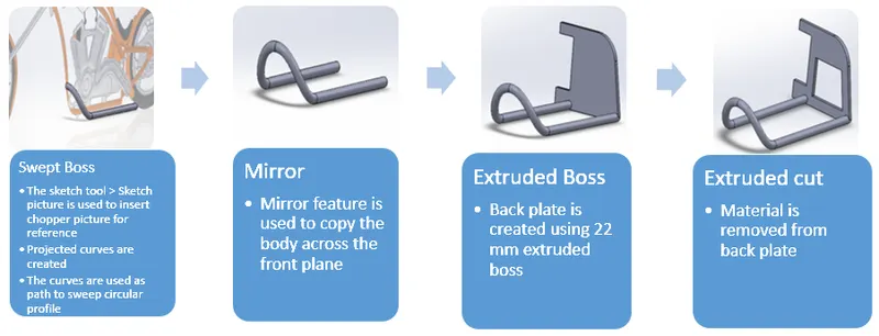
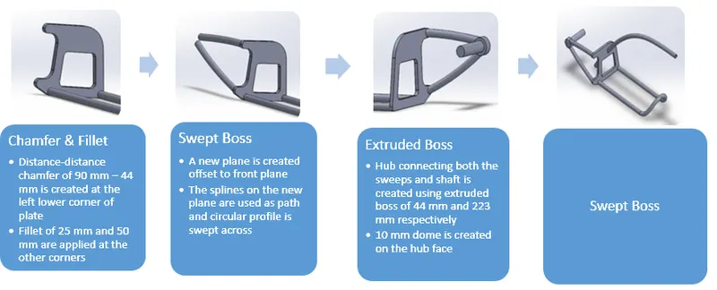
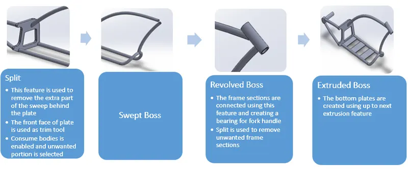
The modelled part:
The rendered part:
Fuel tank:
This is a container to store fuel and supply to the engine. This part is built using surfaces as shown below:
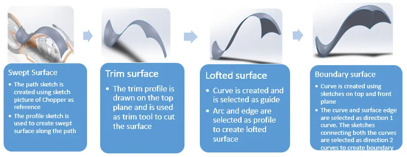
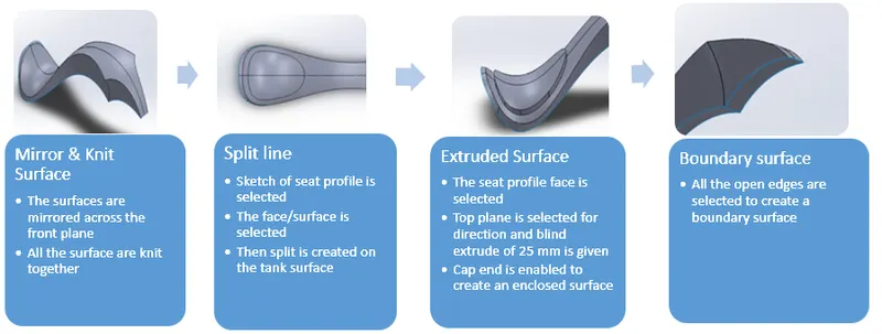
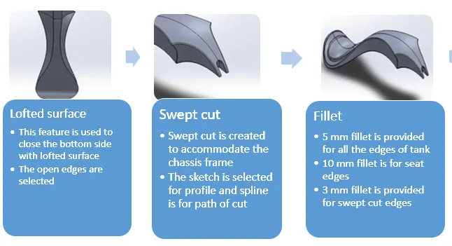
- Trim surface: This function is used to trim the surface intersecting with another surface, sketch or plane
- Swept surface: this creates a new surface defined by the profile sketch along the selected path-curve
- Lofted surface: this feature creates a new surface by using profiles with or without a guide curve
- Boundary surface: this feature creates a new surface that is tangent or curvature continuous on all sides of surface. This creates a superior surface to a lofted surface.
- Split line: this function is used to project an entity like a sketch on the selected surface or face. This function divides the selected face into multiple separate faces.
Modelled part:
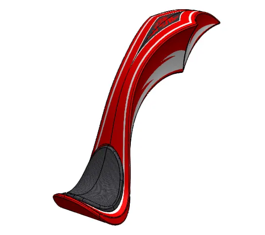
Appearance: Candy red metallic paint is applied to the overall part. The seat region appearance is set to fabric: soft leather and decals are applied on the top and sides of the tank
Rendered image:
Assembly:
The mating conditions between various parts is explained below to obtain fully defined assembly
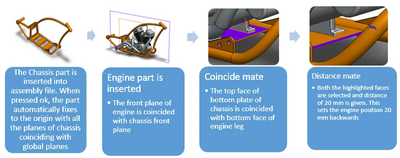
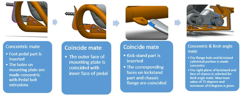
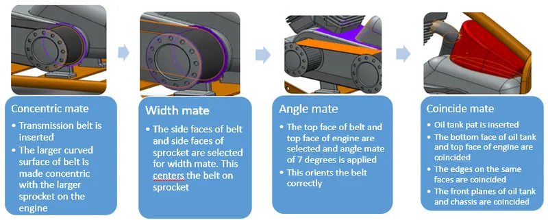
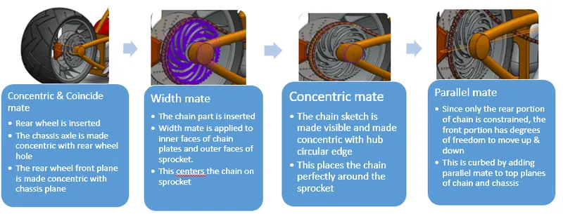
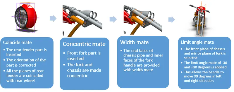
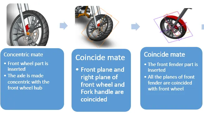
Photo-realistic rendering:
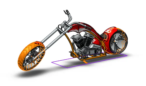
- To set up the vehicle for photo-realistic rendering, the vehicle needs to be parked and shown to be inclining with the support of a kickstand. This posture is created by applying tangent mate between the tyre surfaces, kickstand outer curved surface with the top plane of the assembly as shown below:
- The fork handle angle is set to 30 degrees to make it steered to right.
- Then the assembly file is imported into SolidWorks Visualize
- In the import setting, snap to floor is enabled so that the model touches the floor. The grouping method is set to Appeanrance. This groups the parts based on the appearance. All other settings are enabled such as geometry, decal, appearance etc
Outdoor renders:
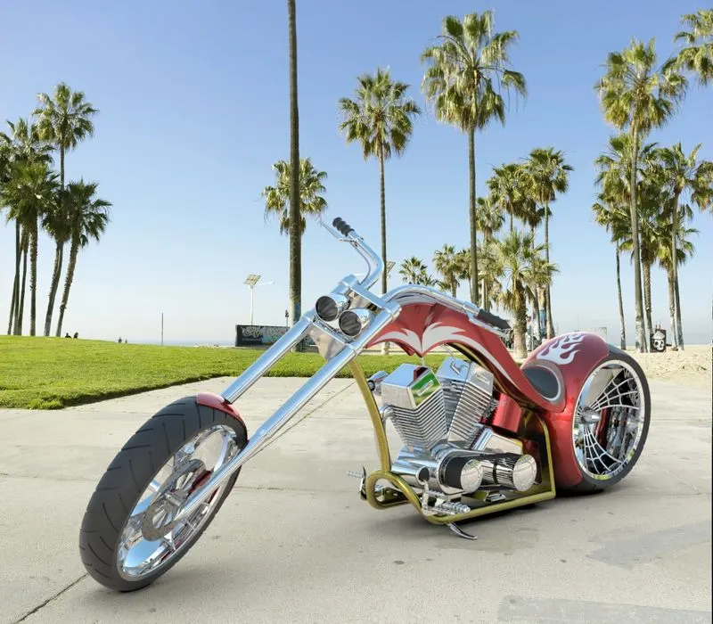
- Default camera view of the chopper is selected
- The environment and backplate is set to Venice Beach
- The rendering type is set to Accurate and the number of passes is set to 300
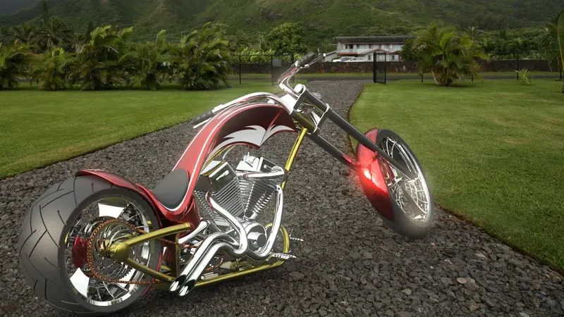
- The custom view of the Chopper is set using arbitrary rotation
- The environment and background is set to Thunder Road
- The rendering type is accurate and 300 passes
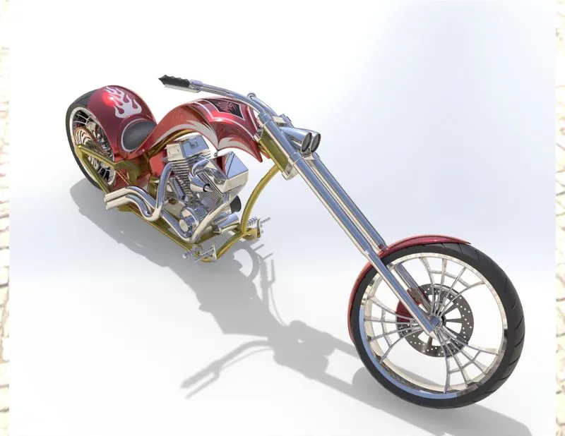
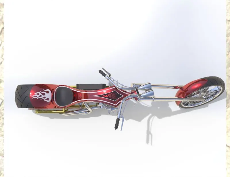
Studio renders:
- The background and environment is set to Plain white
- The rendering type is set to accurate and the number of passes is set to 300
Right-side view:
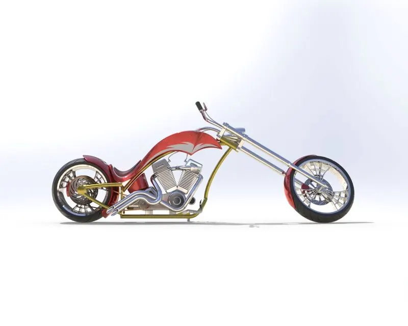
Left-side view:
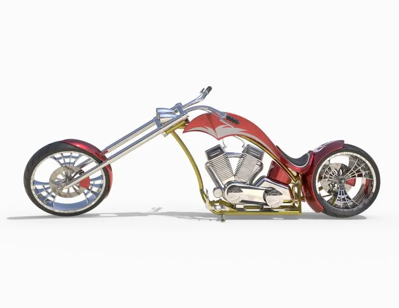
Isometric view:
Top view:
Camera view:
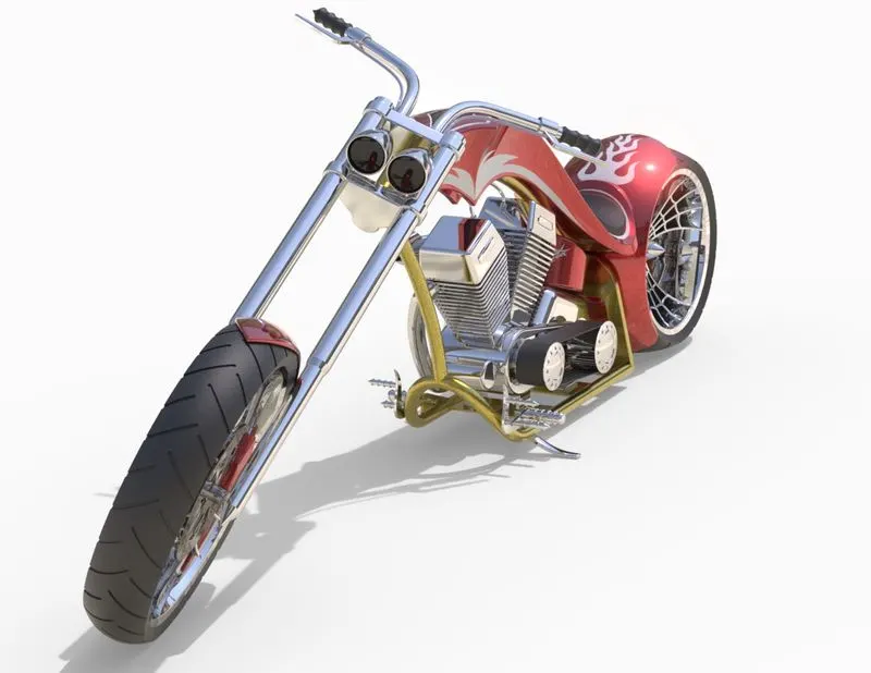
Front view: