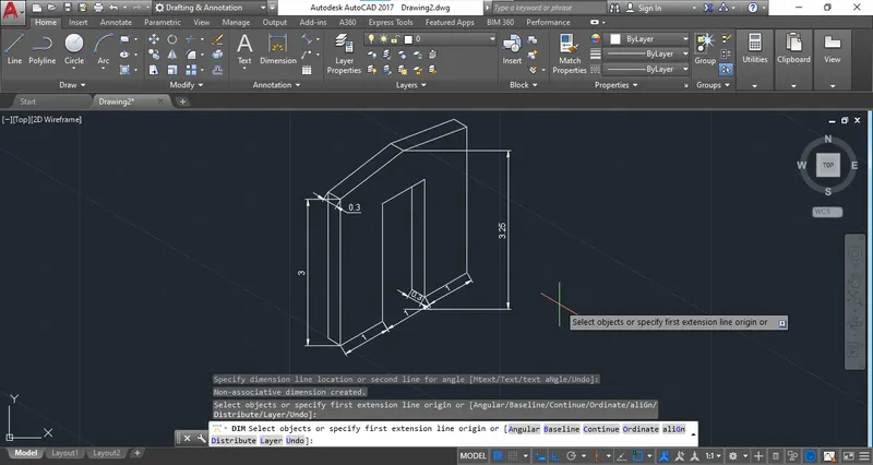
Creating a Floor plan, Footing detail and Isometric view using AutoCad
ANS: C1
C/S Of Load Bearing wall over spread footing:
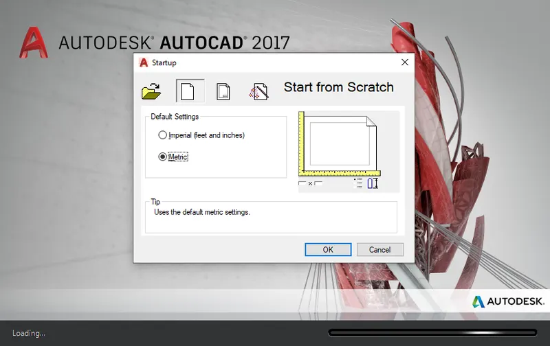
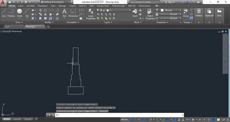
Step 1: Start the new drawing with Matric template.
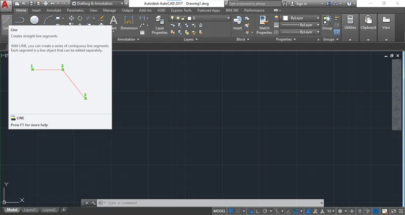
Step 2: Select the line command from tool bar.
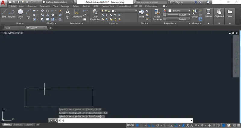
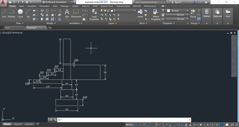
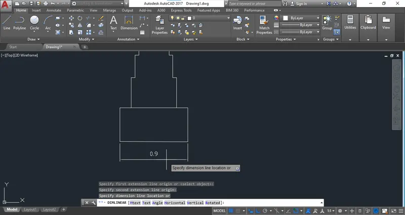
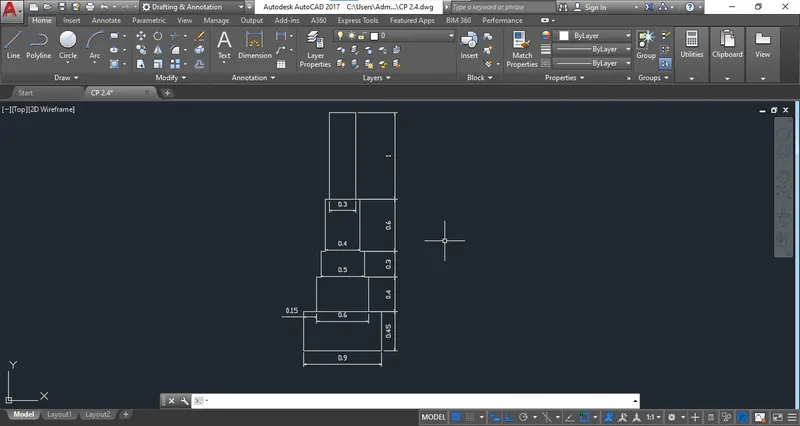
Step 3: Start the drawing with bottom surface of width 0.90 with 0.25 Height.
Step 4: Take the step 1 of footing of size of width of 0.50 with Height of 0.40 & Step 2 of footing of size of width of 0.40 with Height of 0.40.
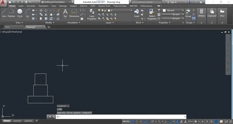
Step 5: Continue the drawing with same procedure.
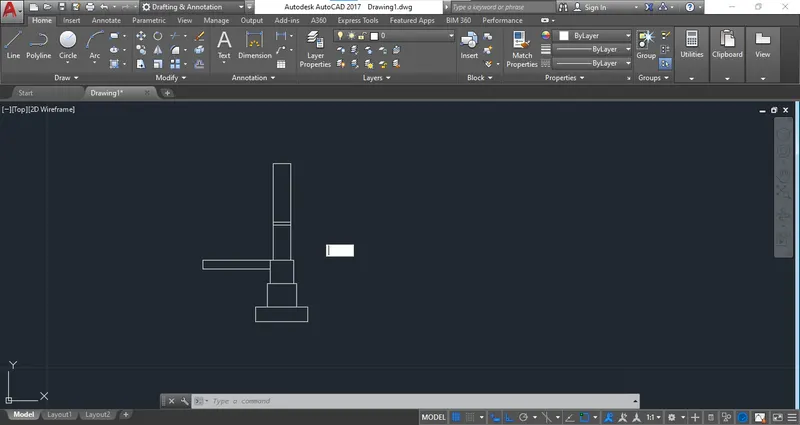
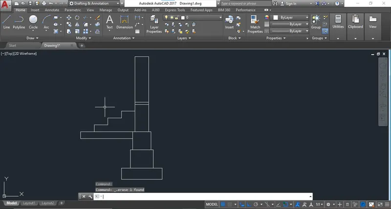
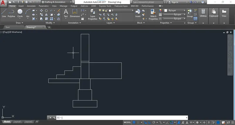
Step 6: Provide the proper dimensions to the drawing.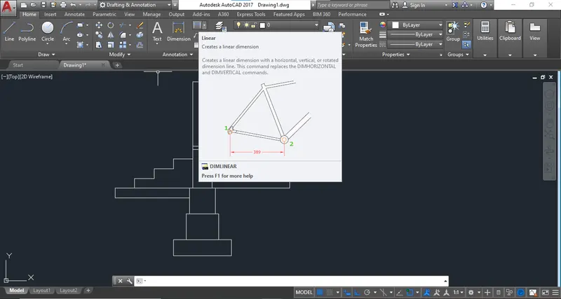
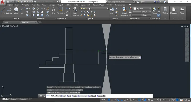
Step 7: The size of arrow and text will not shown properly.
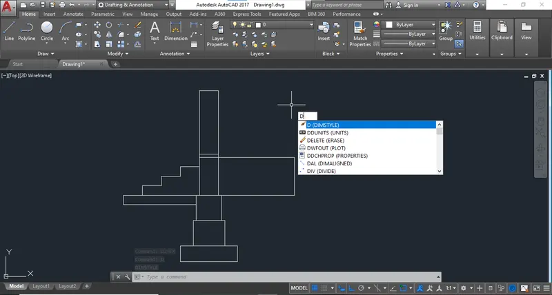
Step 8: Use the "DIMSTYLE" command and change the size of arrows and text.
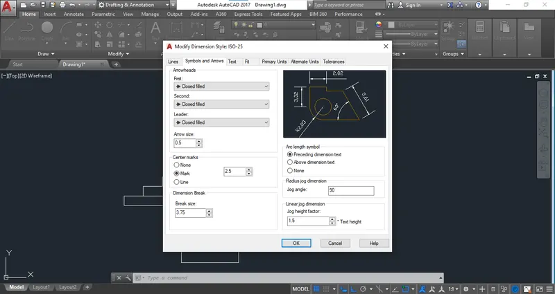
Step 9: By using modify tool change the sizes.

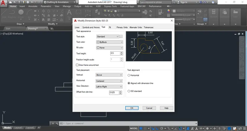
Step 10: Place the proper dimension:
ANS : C2
C/S of ISOLATED FOOTING
Step 1: Start with the metric unit template:
Step 2: Insert the "LINE" Command.
Step 3: Start to draw the Isolated part using relative co-ordinate method and add co-ordinates.
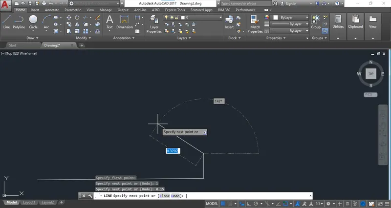
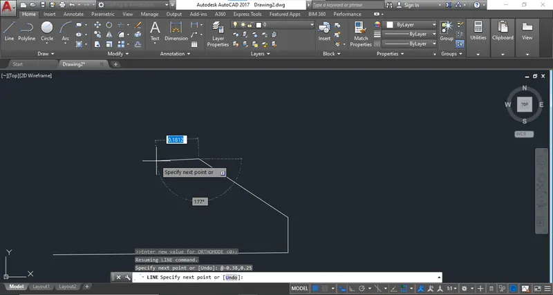
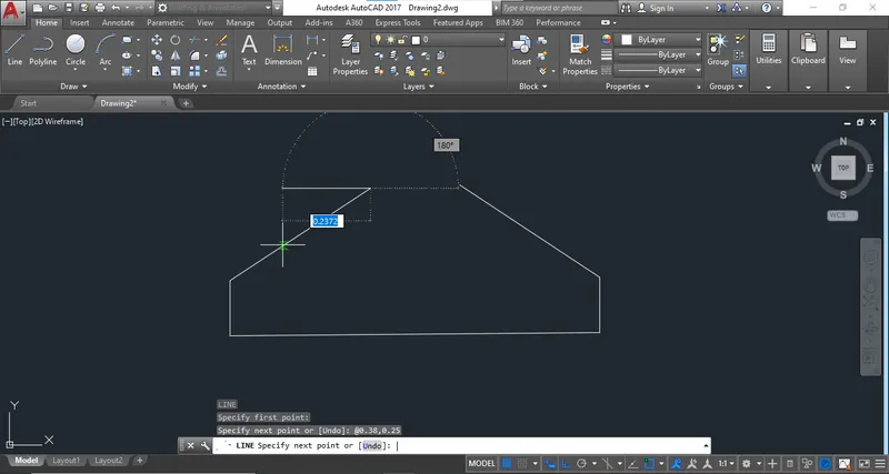
Step 4: Start the top part.
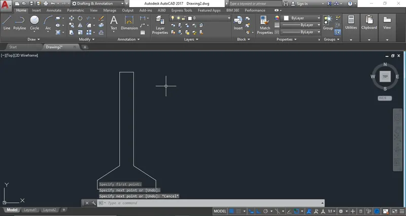
Step 4: To create the reinforcement details use "OFFSET" command.
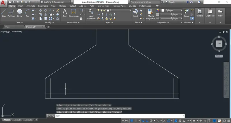
Step 5: Use trim tool to remove some extra portion.
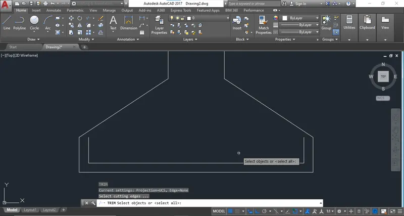
Step 6: Create the inner part of the column portion.
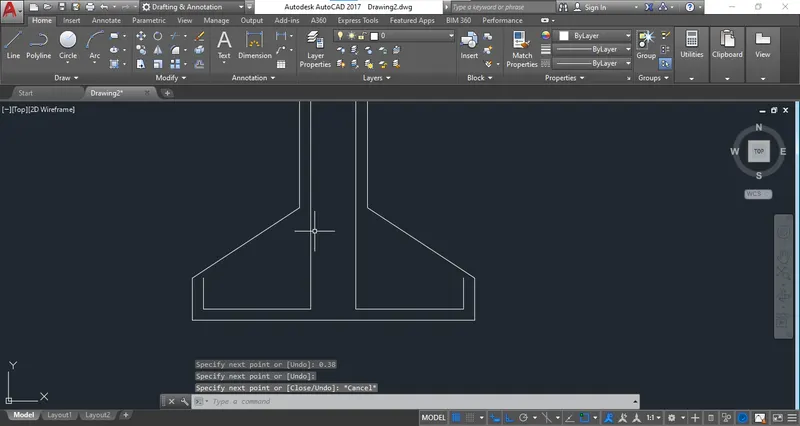
Step 7: Again use "OFFSET" command to provide shear links in Colum9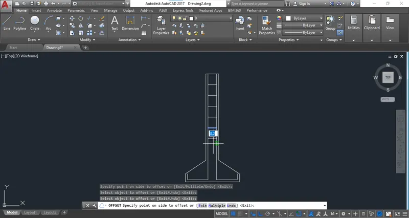
Step 9: Complete the drawing and Provide the dimension.
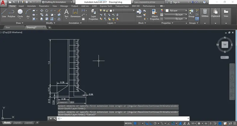
ANS: C3
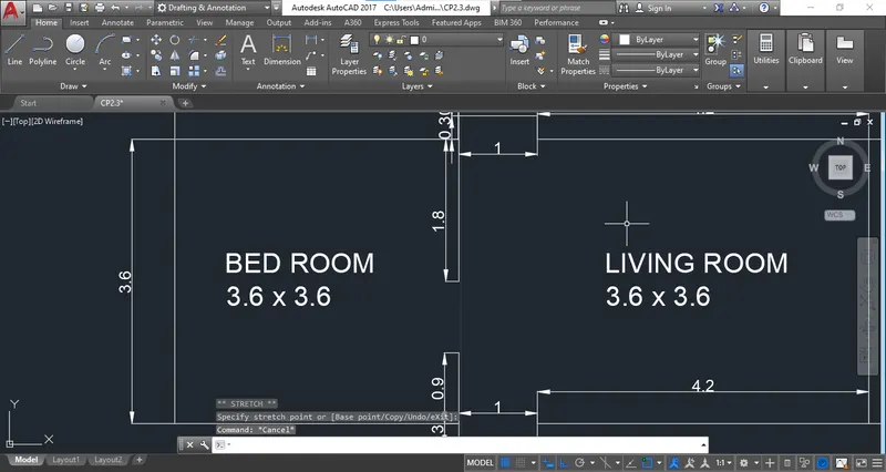
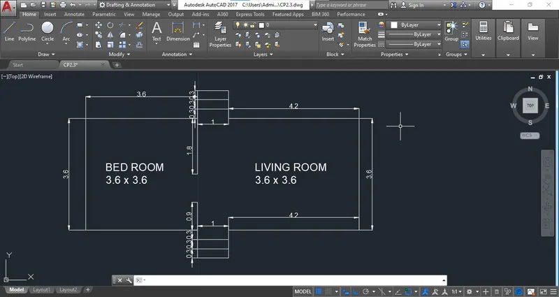
Line Diagram of A Two Bedroom Building.
Step 1: Start the drawing with Metric Template.
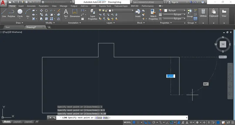
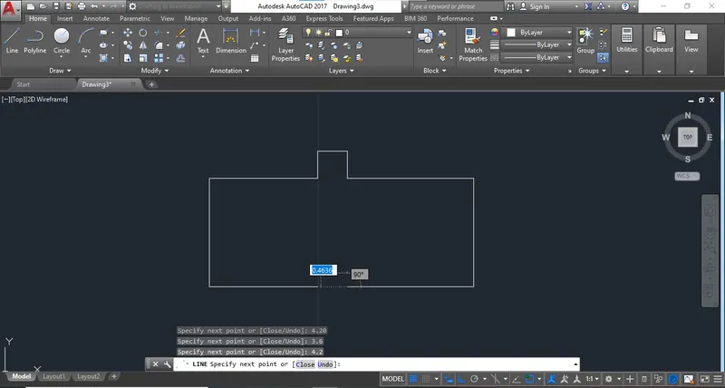
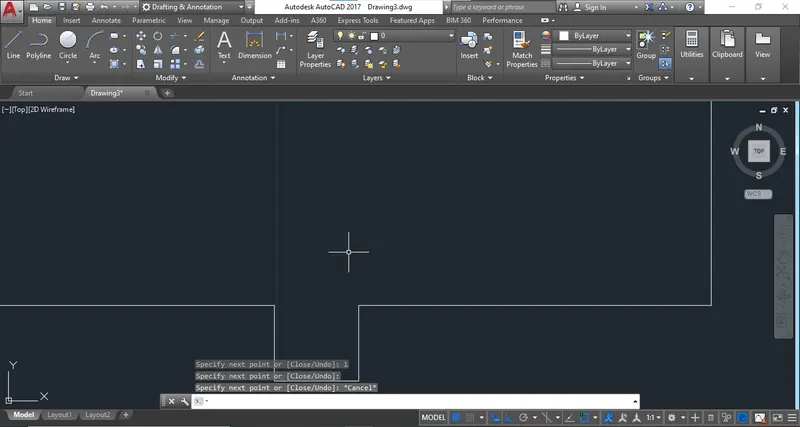
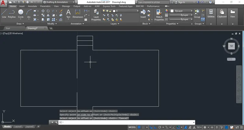
Step 2: Use an offset command to create steps of stairs.
Step 4: Add dimesions.
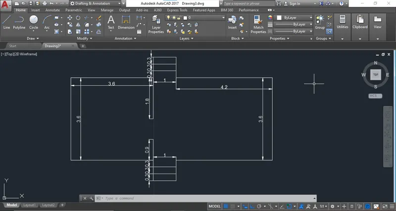
Step 5: Add Text and dimension of room. Complete the drawing.
ANS: C4
C/S of Load Bearing Wall Showing Foundation Details.
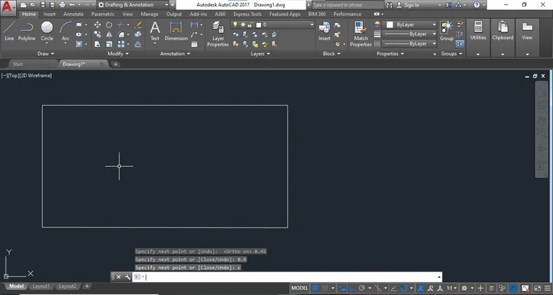
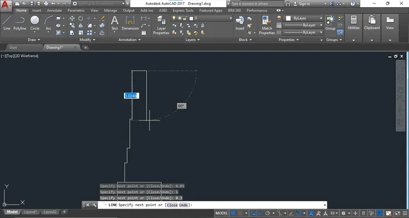
Step 1: Start the drawing with Metric template.
Step 2: Use Line command start to Draw.
ANS: C5
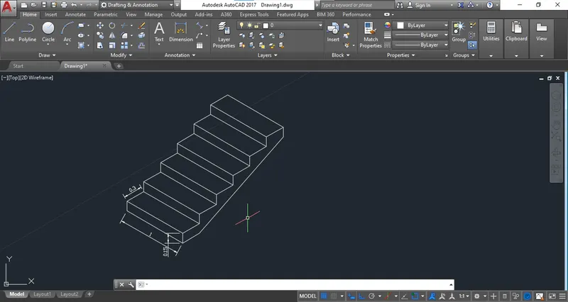
Isometric View of Step.
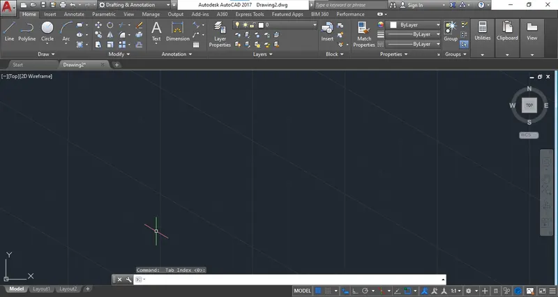
Step 1: Select the metric unit template.
Step 2: To create an Isometric view select the isometric snap.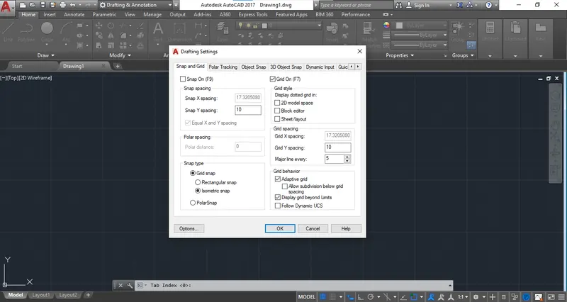
Step 3: We are entering in Isometric window now which having the isometric grid.
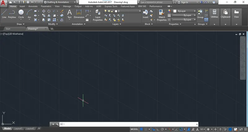
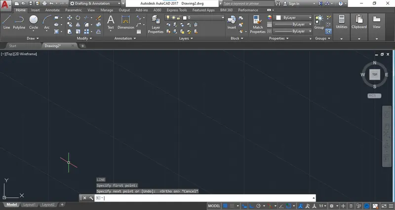
Step 4: Select an LINE command to start the drawing.
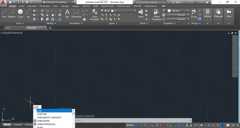
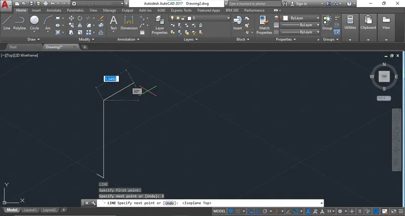
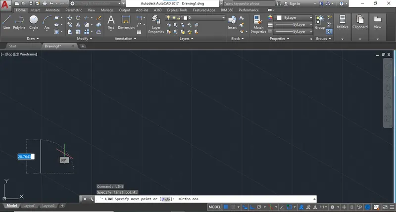
Step 4: Select Right Isomtric plane to create the outline of step.
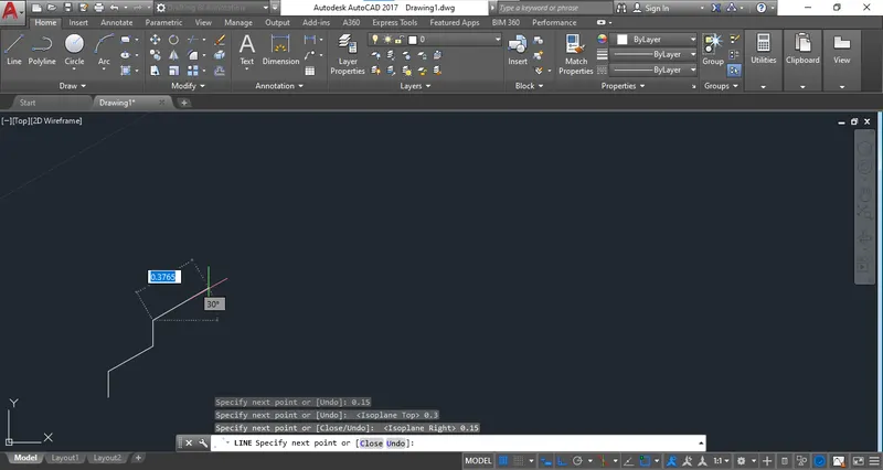
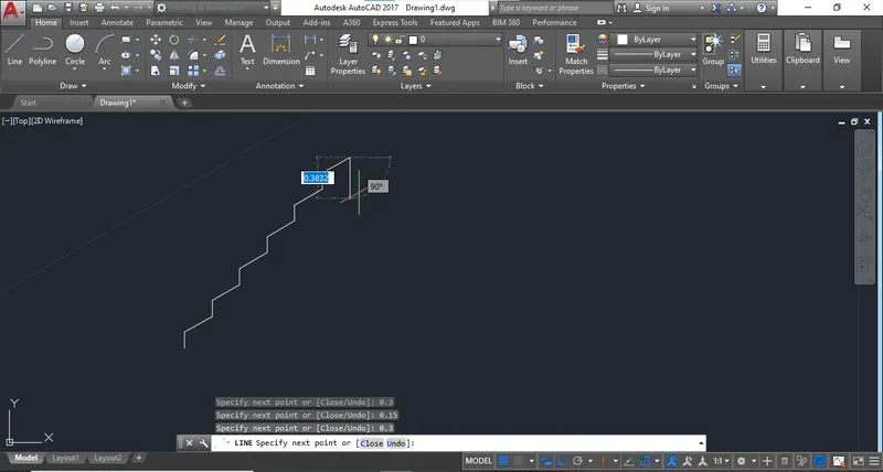
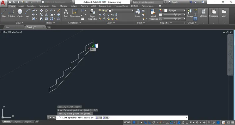
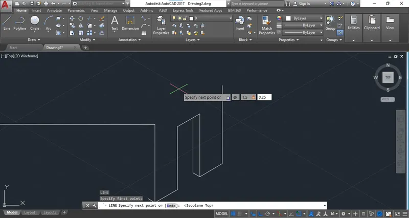
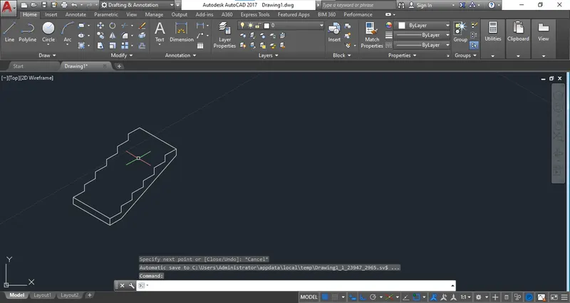
Step 5: To provide an width of step change the isometric right plane to isometric left plane or press "F5" to change the plane.

ANS: C6
Isometric view of Gable wall.
Step 1: Select the isometric snap to create isometric view.