To model beams and bracings for industrial steel structures using TSD
Q.1 Ans
Aim: Create beam properties for First floor and model the beams.
Introduction:
- Steel beams are most often used as supports in structures, ensuring their safety and stability, while using the least amount of material. As such, they are one of the most cost-effective construction methods.
- Both types of beams can be used for multiple supporting roles. However, all of the different shapes and sizes are designed to cater to specific use cases.
- Steel beam can be found in almost any structures as supports columns. Typical applications include building construction (Both commercial and residential), bridges, stadium, warehouses and hangers.
Procedure:
Step 1:
- We have to model beams on first floor.
- Go to First floor level.
- Create the properties for beams.
- Go to Manage Property Set -> New -> Steel Beam.
- Add properties for beam sections FB1, FB2, FB3 as ISMB 400, ISMB 350, ISMB 300 Respectively.
- Make changes as shown in below image.
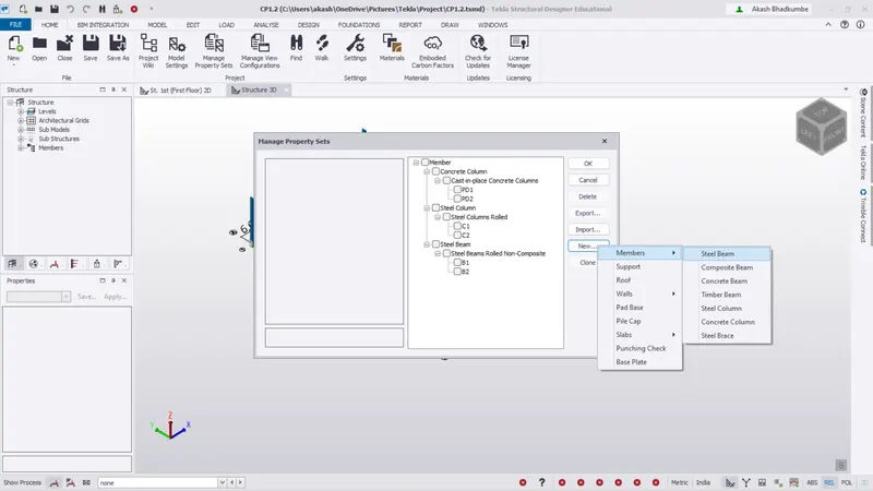
- The property sections are added as below.

Step 2:
- Go to First floor plan and add the beams.
- Select the section property FB1 and draw beam carefully from one column to another column.
- Go to Model -> Steel -> Beam then select the section property.
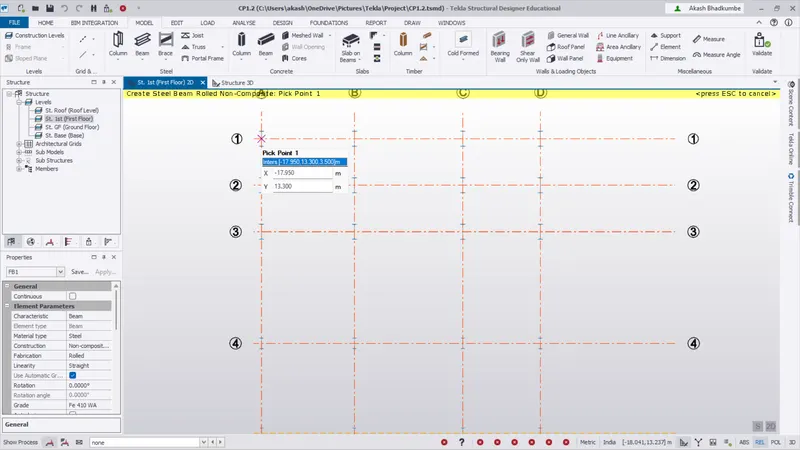
- Add all the beams one by one with property sets FB1, FB2 & FB3.
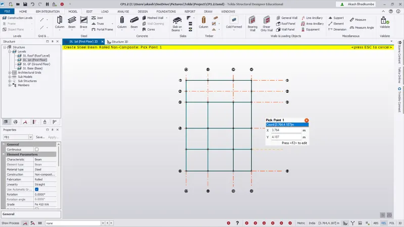
- Create the staircase area with proper dimension.
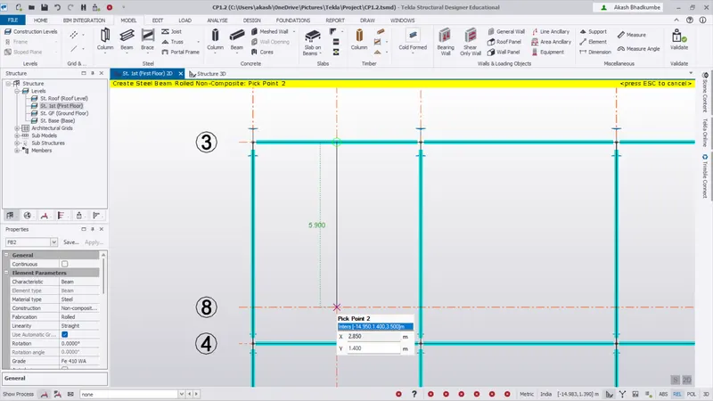
- Add some intermediate or secondary beams as per room dimensions.
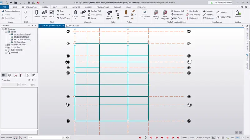
- All the beams at First floor level is added successfully.
- Click on validate to check the errors in modelling.
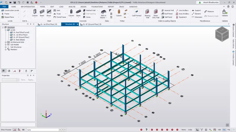
Conclusion:
- The beams are added on First Floor.
- There are no clash between column and beams.
Q.2 Ans
Aim: Create rafter beam on second floor as roof and moment frame action in one direction and add bracings at locations as per the design intent.
Introduction:
1. Rafter:
- A Rafter is a long board that supports the peak of a roof.
- The Rafters are designed to support the roof shingles, roof decks and its associated loads.
2. Moment Frame:
- A Moment frame is a special type of frame that uses rigid connection between each of its constituents members.
- This configuration is able to resist lateral overturning forces because of bending moment and shear strength that is inherent in its members and the connecting joints.
3. Bracing:
- A bracing systems serves to stabilize the main girders during construction, to contribute the distribution of load effect and to provide restraint to compression flanges or chords where they would otherwise be free to buckle laterally.
Procedure:
Step 1:
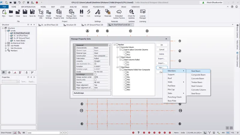
- Go to Manage Property set -> New -> Steel Beam
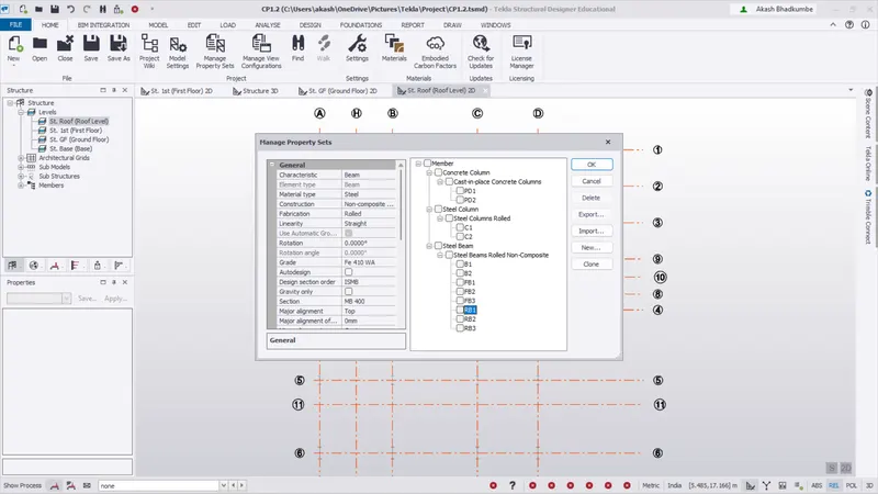
- Create section properties for beam at Roof level.
- Add beams RB1, RB2, RB3 as ISMB 400, ISMB 350, ISMB 300 respectively.
Step 2:
- To add beam go to Model -> Steel -> Beam.
- Select the section property from property browser and then add beams from one column to another column carefully.
- Check that the beam start and end points are not clash with column.
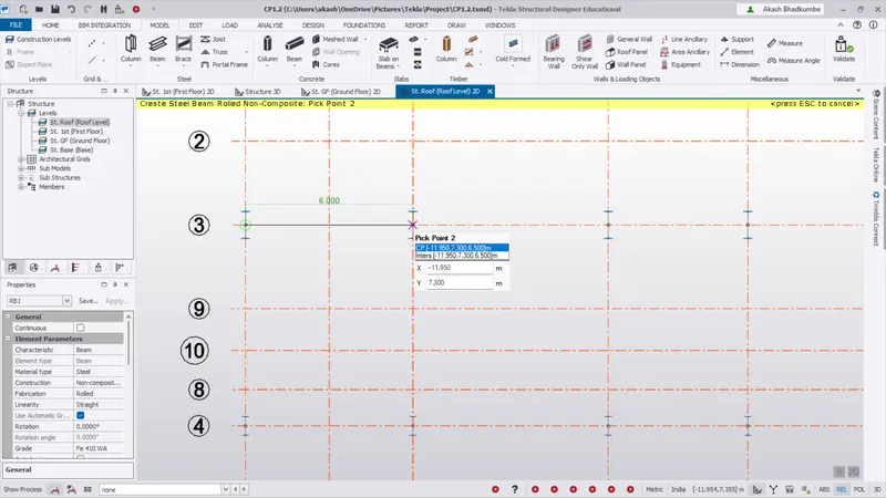
- Add all the bams at roof level.
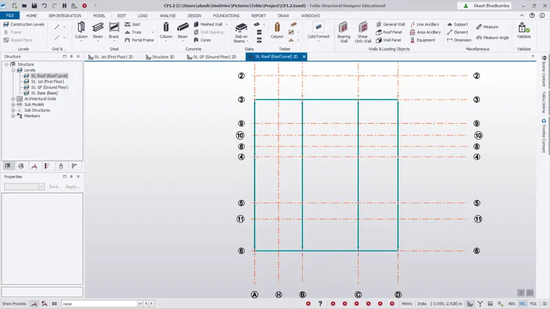
- Add secondary or intermediate beams.
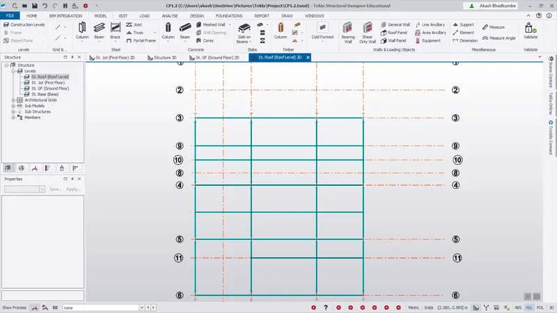
- The beams at second level are added click on validate and check the modelling error.
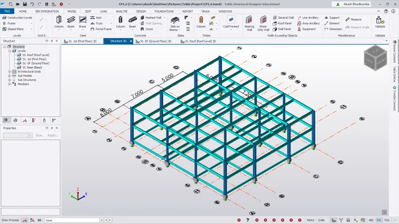
- There is no clash between beam and column.
Step 3:
- To create rafter we have to add model frames.
- To add model frame go to model -> Levels -> Frames.
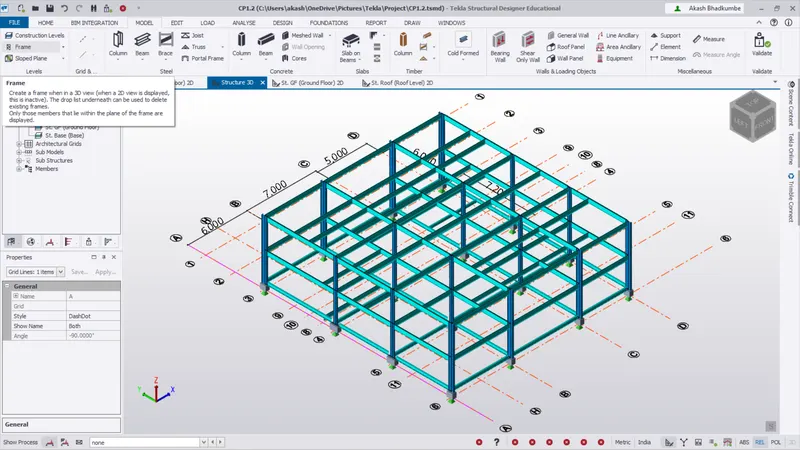
- Click on grid line to create model frame.
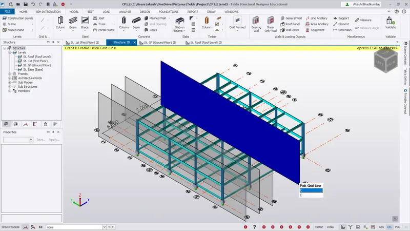
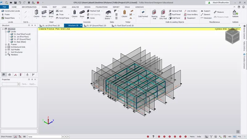
- The model frames are added on each and every grid.
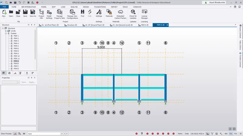
- Select created Model frame and calculate the distance of roof top from second level.
- To create a rafter first we have to add the section property for the rafter.
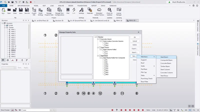
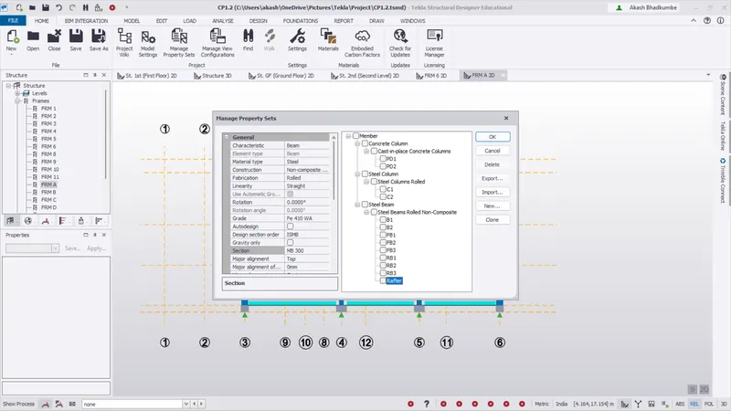
- Add rafters from model frame so it will created properly. Select the model frame on grid and create rafter for at each level.
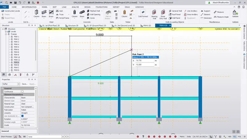
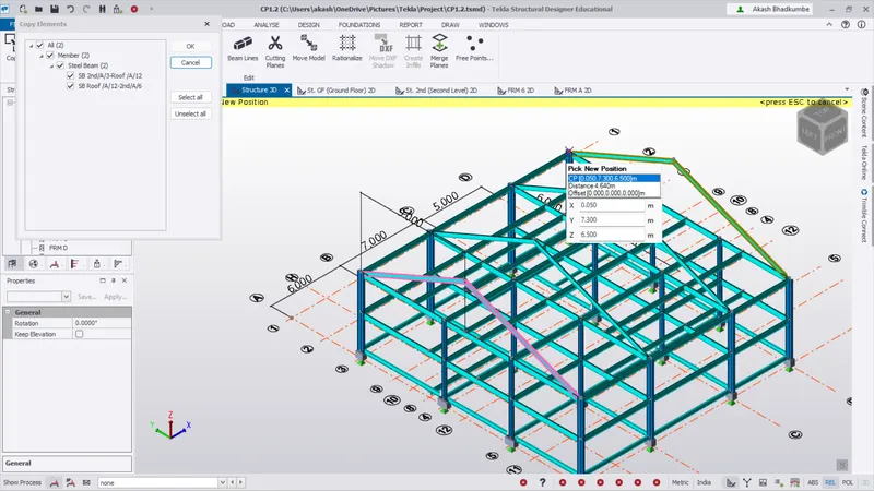
- Create a property for ridge and add ridge.
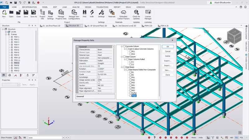
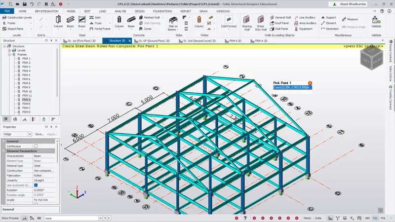
- Cleck on validate and check errors.
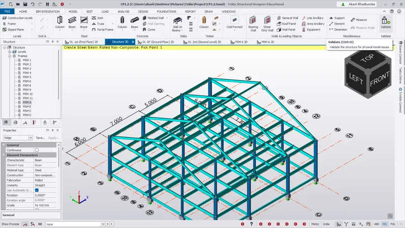
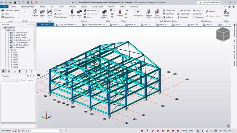
- To create bracing. Add new property for Bracing. Select the model frame and add the bracing with created property on Side and on Roof.
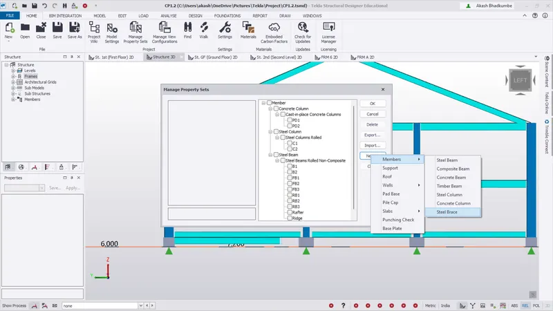
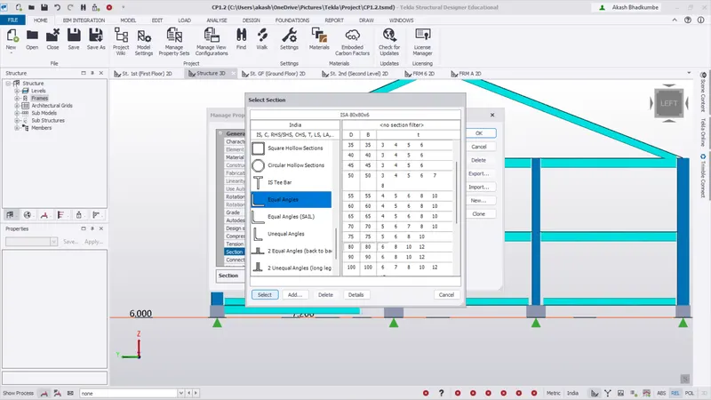
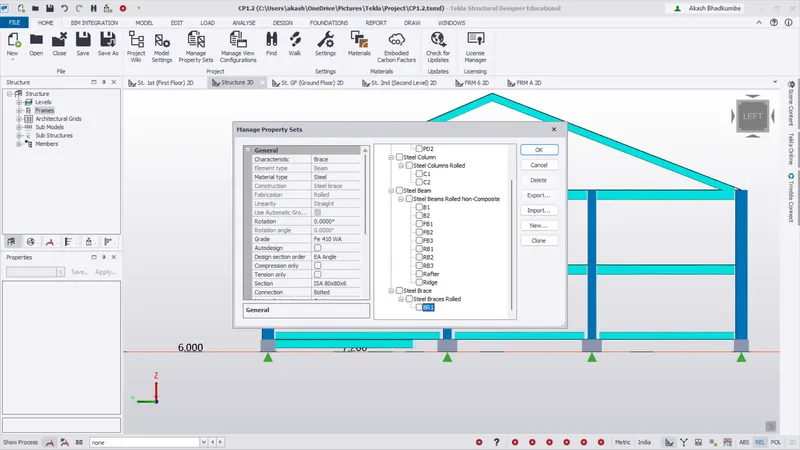
- After adding the property for Bracing.
- Go to Model -> Steel -> Bracing. Select the bracing type as X Brace.
- Select the model frame to add the bracing and select 4 points to create a bracing.
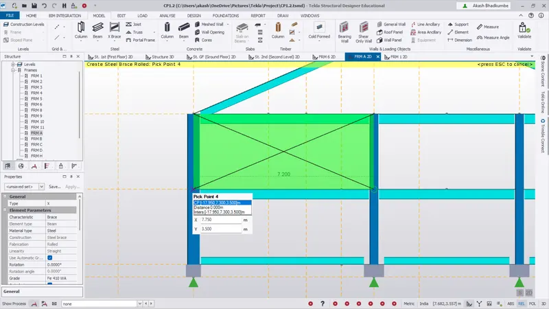
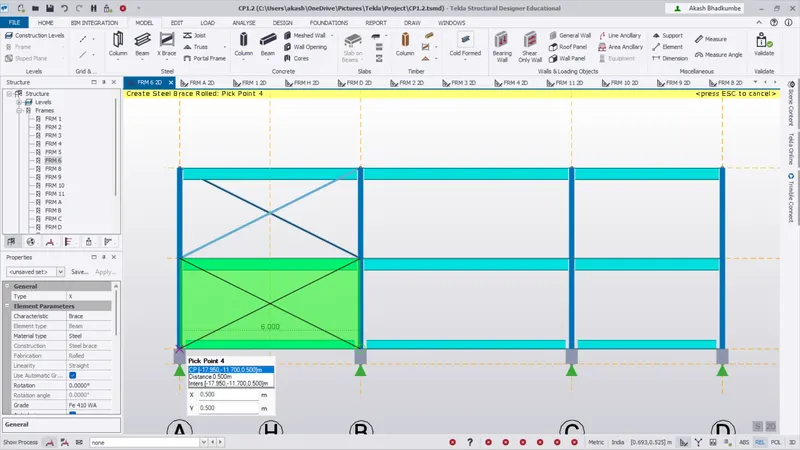
- Bracings are created at Roof and side.
Step 3:
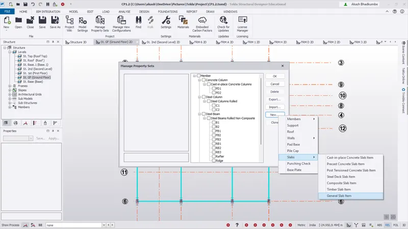
- To create a slab property Go to Model property set -> New -> Slab -> General Slab item.
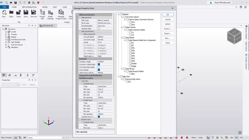
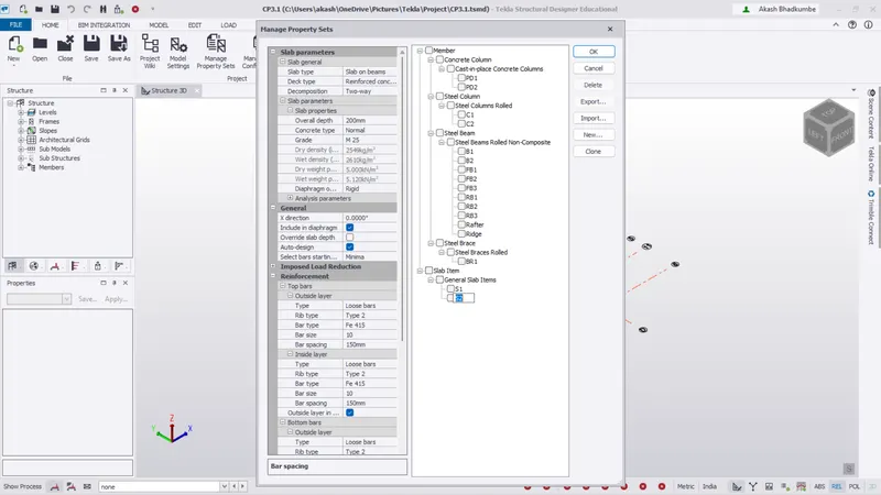
- Create two property sets S1 & S2 for One way & two way respectively.
- Change the properties as given below.
- Model slab on Ground Floor, First Floor & Second floor level.
- Go to Model -> Concrete -> Slab on beam. Draw slab on respective level.
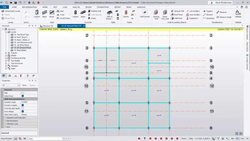
- Do not create slab in staircase area.
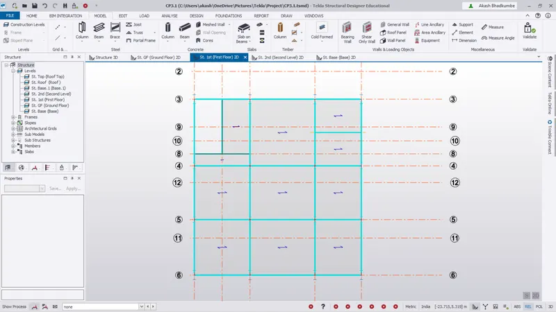
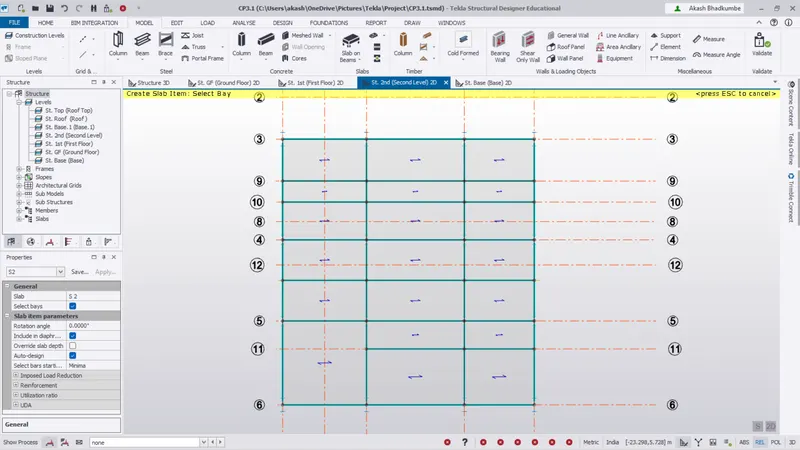
- Slab is created on Ground, First & Second Level.
Step 4:
- Create a Wall panel & Roof panel go to Model -> Walls & Loading object -> Wall Panel/Roof Panel.
- First we will go through the wall panel. Select the wall paneling command and select two diagonal points to create a wall.
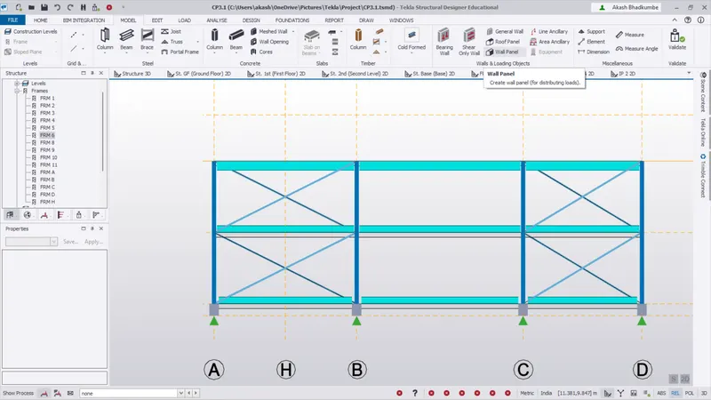
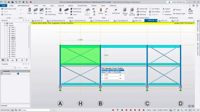
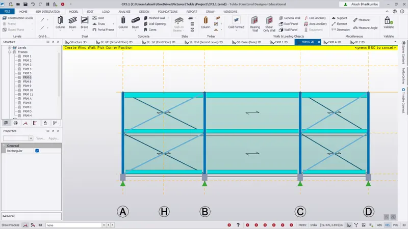
- Similarly create the wall panel for all sides.
- Similarly create roof panel.
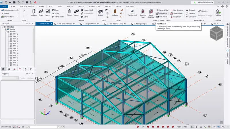
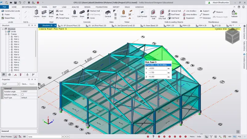
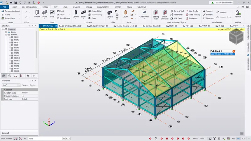
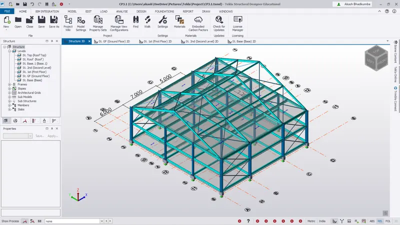
Conclusion: The structure ready with Primary Beam, Secondary beam, rafter, Bracing, Slab, Roof Panel & Wall panel.