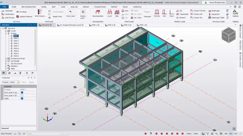
To calculate the dead , live and wind load for RC residential structure and to apply them using TSD
Q.1 Ans
Aim: Calculate dead load in design report based on IS code and apply dead load on the model.
Procedure:
Given Data,
- Finishes of 50mm
- Slab Thickness as per the design
- Brick wall load
- Roofing Load.
Step 1: Calculation of Load:
- Slab Load = (Model Slab in Software)
- Finishes loading (50mm Thickness) = `0.05xx24 kN//m^2`= `1.2 kN//m^2 (Area Loadi ng)`
- Consider a brickwall with cement plaster = `225 mm`
- Unit weight of Brickwall = `20 kN//m^3`
- Floor to Floor Height (Ground to First Floor) = `3.6 m`
- Brick wall loading = `(225xx20xx3.6)/1000 = 16.2kN//m`
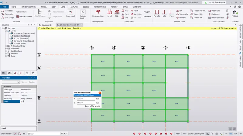
- Roof wall loading = `1.5 kN//m`.
Step 2:
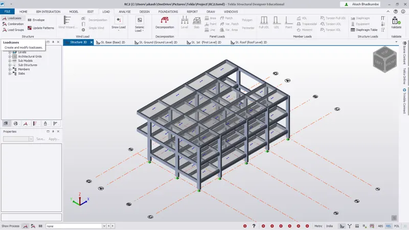
- Open the previously saved model of RC building.
- Go to load cases and check that there is any load case for DEAD load.
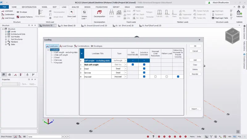
- Now click on loadcase and select the Dead load.
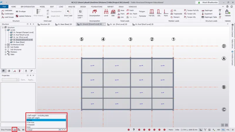
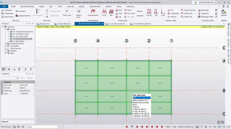
- Go to Load -> Panel load -> Area load and apply the value of area load for floor.
- In property panel change the load value to `1.2 kN//m^2`.
- Go to ground floor and click on the slab to apply area load.
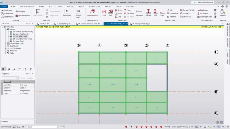
- Similarly apply the load for First floor with same value.
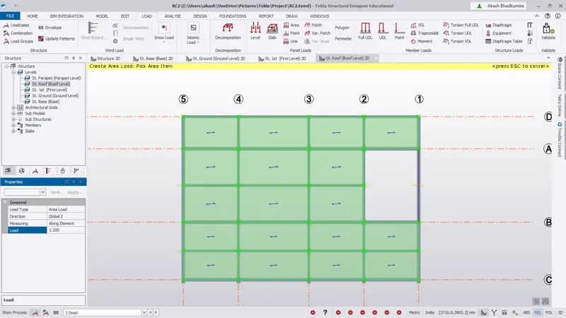
- Change tha load value as `1.2 kN//m^2` for roof floor.
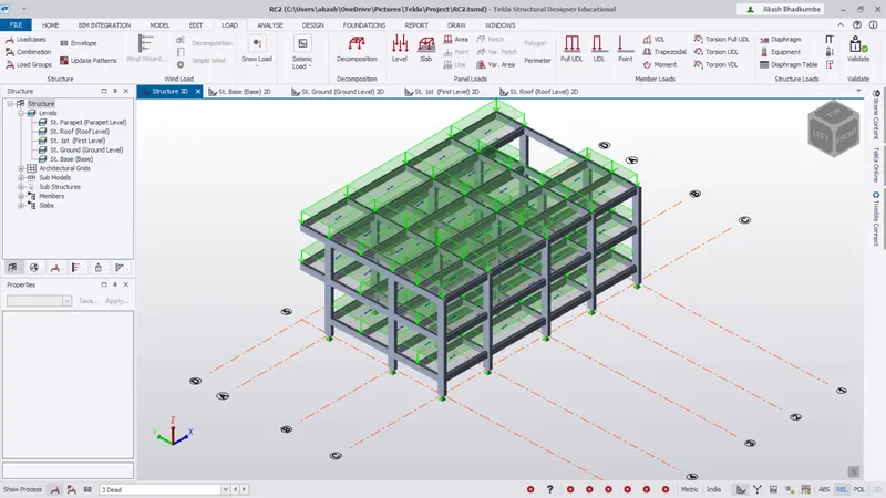
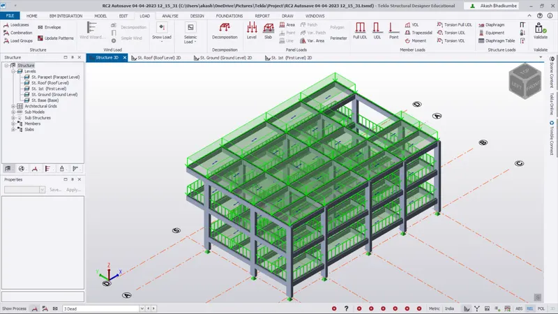
- The area load is added on all the floors.
Step 3:
- Apply brickload on all the floors.
- Go to Load -> Member load -> Full UDL. Change the load value from property browser to `16.2kN//m`.
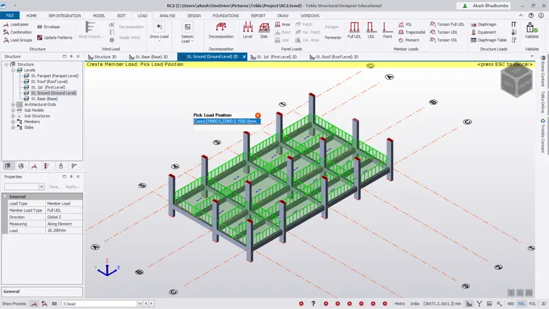
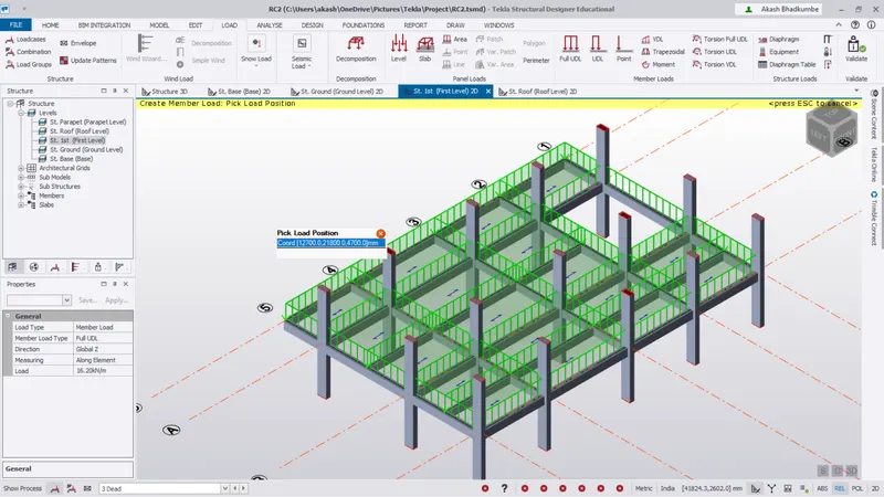
- Similarly apply Full UDL on first floor with `16.2kN//m` value.
- Apply the `1.2 kN//m` load value on roof floor.
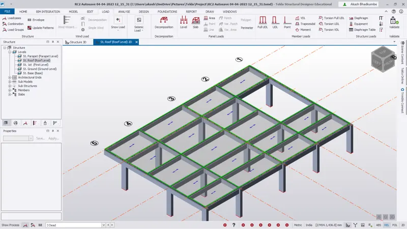
Conclusion :
- Dead load is applied on all the floors with respected values.
Q.2 Ans
Aim: Calculate Live load and design report based on IS code and apply dead load on the model.
Peocedure:
Step 1:
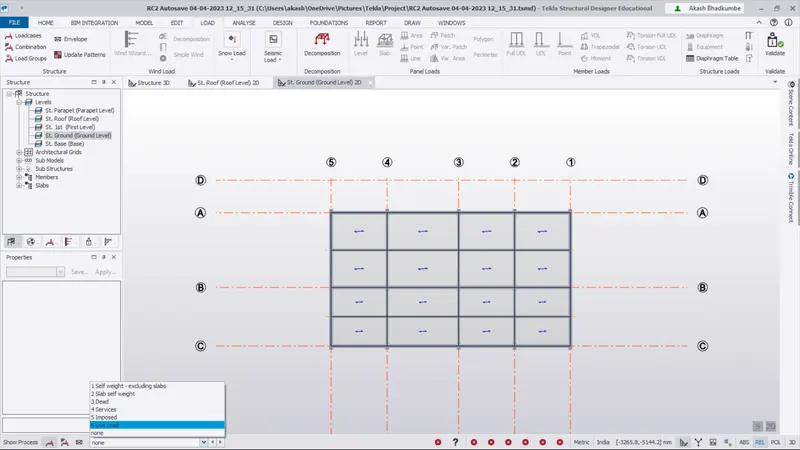
- Go to Load -> Structure -> Load cases. Add the new load case for Live load.
- Go to the bottom left corner and change the load case as Live and apply the live on the floor.
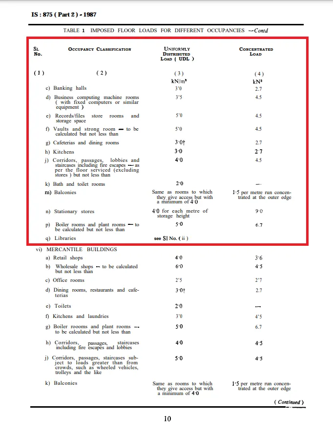
- As per `IS 875-Part (II):1987,Tabl e no 1`. There are different load values for different room occupancy classification.
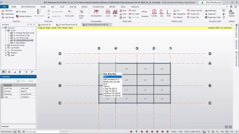
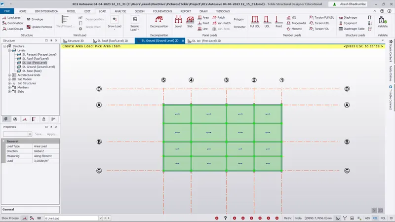
- Change the load value and apply the area load on Ground floor slab.
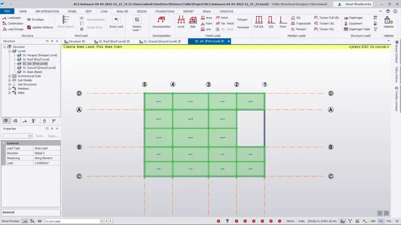
- Similarly apply on the first floor with same load value of ground floor.
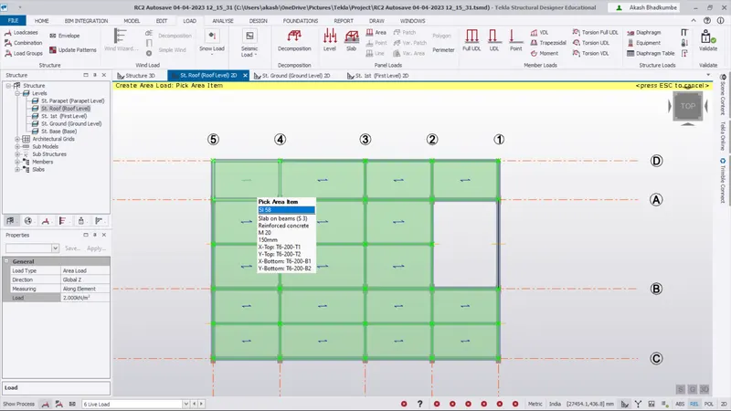
- Similarly as per Table No 1 apply the load value for roof level.
Conclusion:
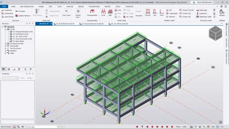
- The Live load is applied successfully on all the load floors.
Q.3 Ans
Aim: Generate mannual wind loading in the design report based IS code as per the following input.
Procedure:
Step 1: Given data,
- Basic Wind Speed = `50m//s`
- Terrain category 2.
Calculation:
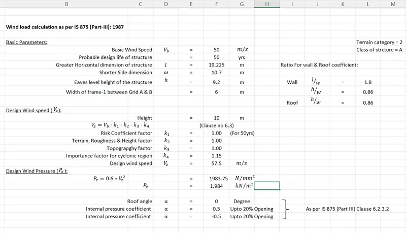
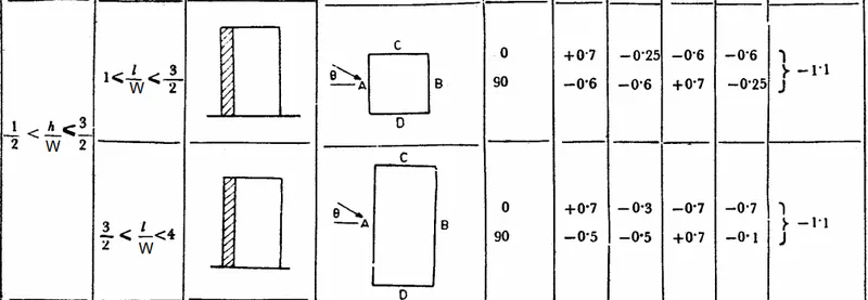
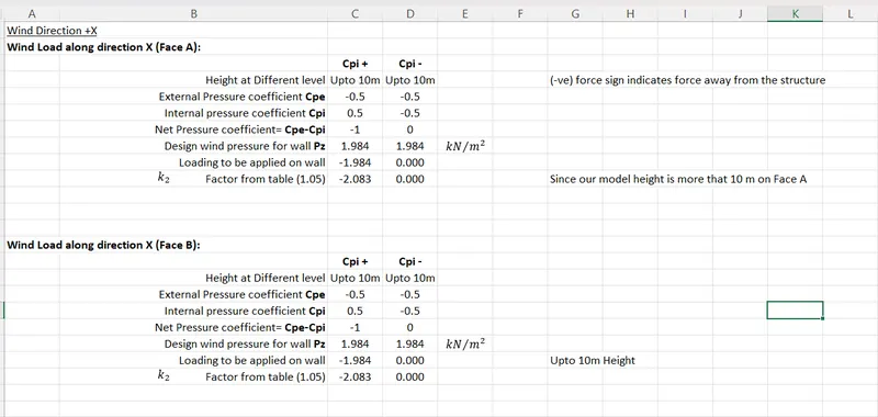
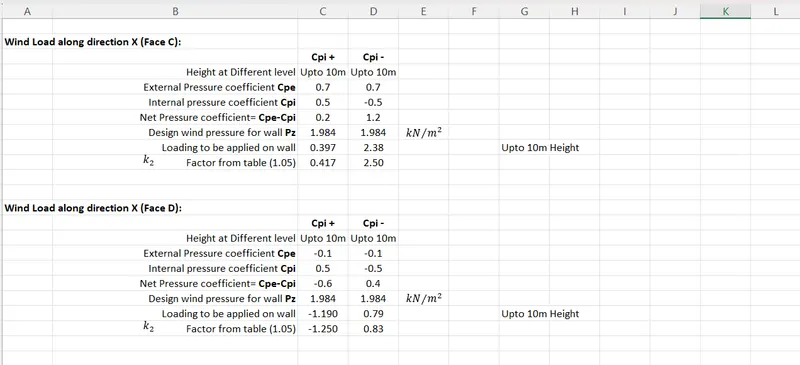
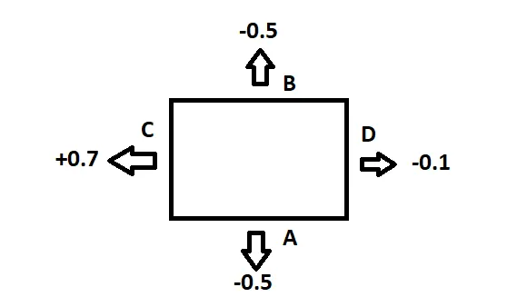
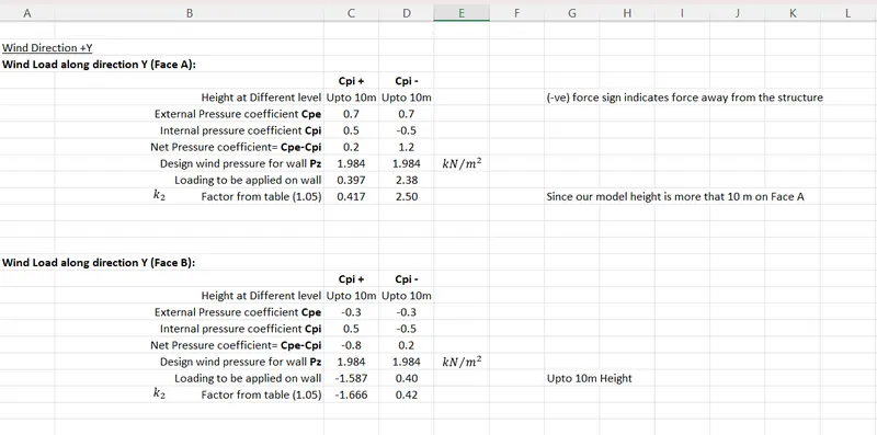
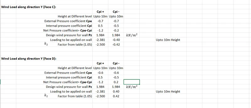
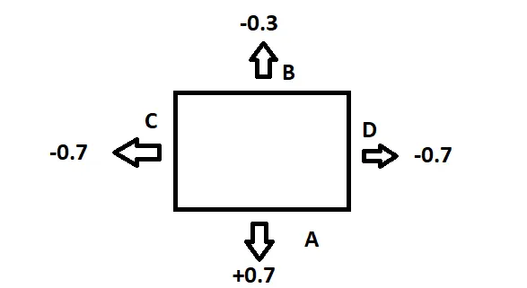
Conclusion : Mannual calculation of Wind load as per `IS 875-Part(III):2015`is done.
Q.4 Ans
Aim: Based on the above calculation apply the loadings on the model.
Procedure:
Step 1:
- As per calsulation we have to apply the wind load coefficient on the structure.
- First we will create the frame on the structure to create wall panels and to apply loads.
- Go to Model -> Levels -> Frames and create frames on every grids.
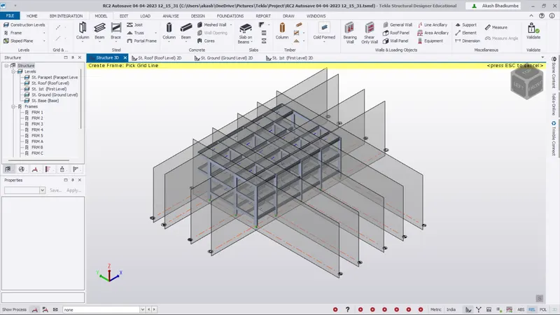
- Select the external frames and create wall panels. Go to Model -> Wall & Loading objects -> Wall panels.
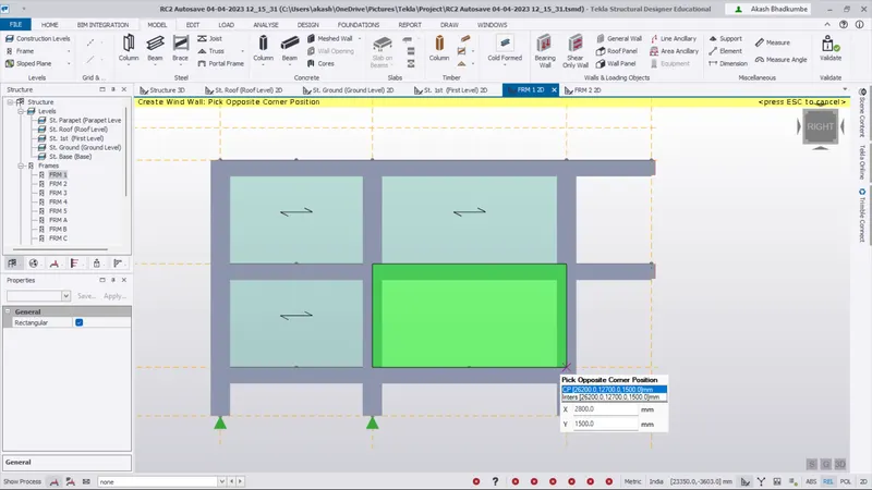
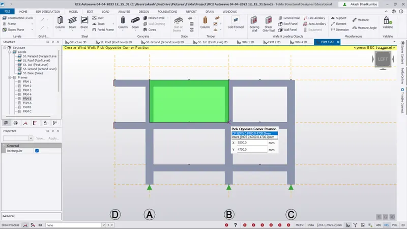
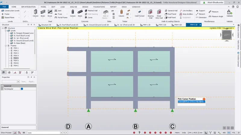
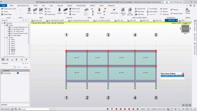
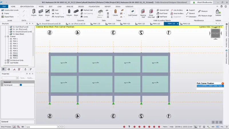
- Wall panels are created on all the external grids.
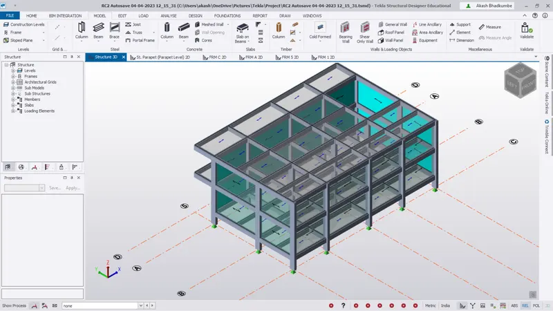
Step 2:
- Go to the Face A on C Frame and select the load case as +Y +Cpi from bottom left corner.
- Go to Load -> Panel Loading -> Area load and change the value of loading.
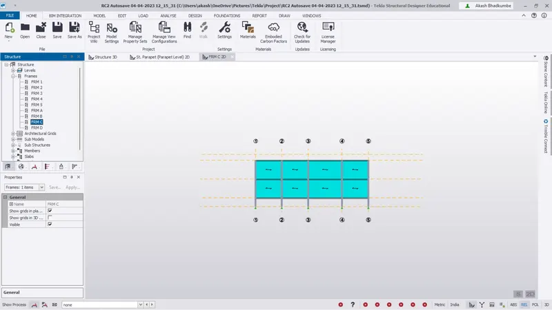
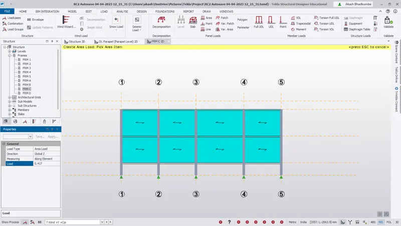
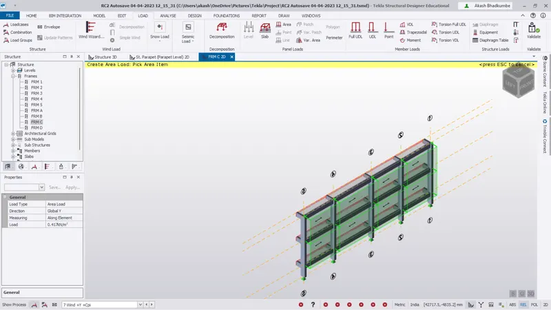
- Similarly select the faces one by one and add the loading on external walls with respective faces and values.
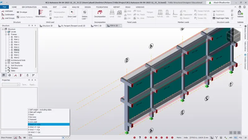
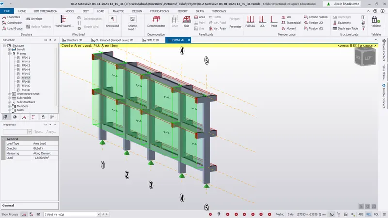
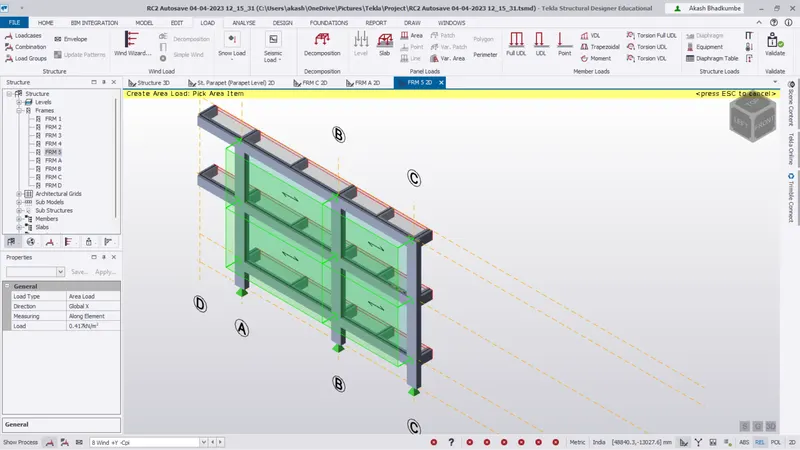
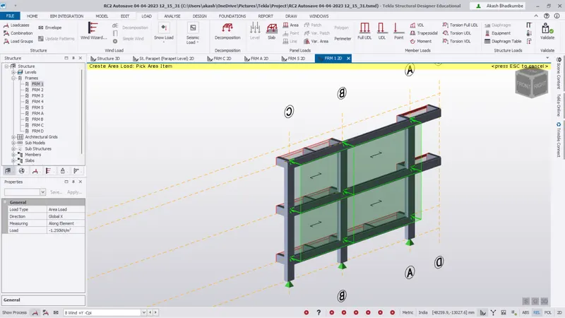
Conclusion:
- The wind load is added on all the external wall panels.