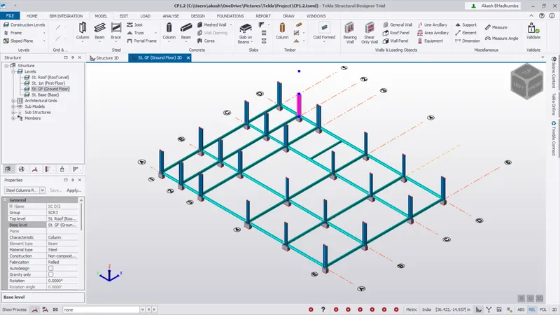
To model columns for industrial steel structure using TSD
- Introduction:
- The Pedestal is the foot or support of column. It is used where the column load is very high, and we required the more depth around the column edge to transfer the load and prevent failure of footing, at the time, we provide a pedestal to transfer load safely from column to footing.
- Pedestal is mainly used in steel structure where the column load is very high.
- Pedestal is a compreession member who has the length to least lateral dimension is less than 3.
Q.1 Ans
Aim: Create a column properties for different types of pedestal members and lateral members and model in the grids created as per the assignment 1.
Procedure:
Step 1:
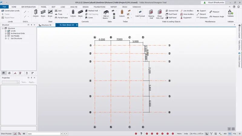
1. Open the TSD file of grids created as per assignment no 1 in challenge no 1.
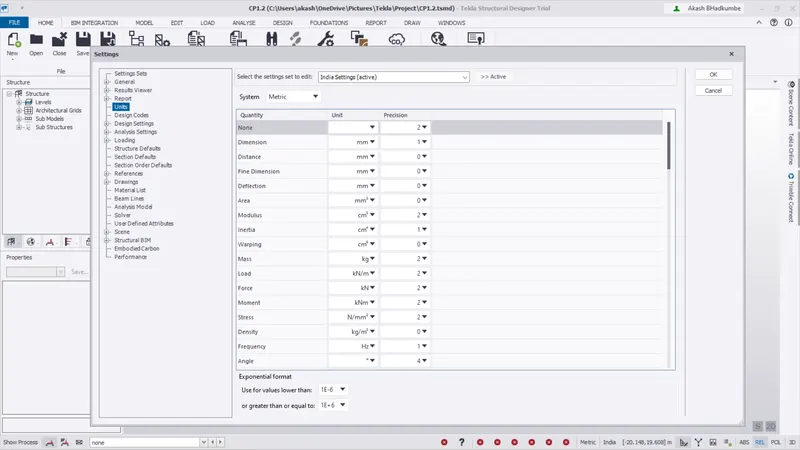
2. Before modelling we have to do some design settings.
3. Go to Home -> Settings -> Units.
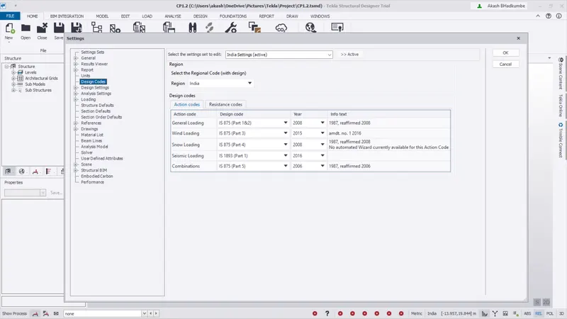
4.Check the design codes.
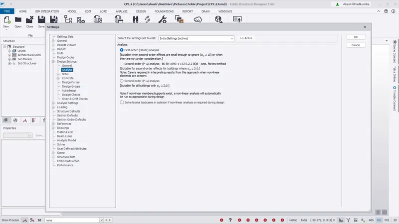
5. Go to analysis and check that we are working on First order analysis. In First order analysis the stiffness of structure is assumed to be constant and unaffected by changes in the geometry of the structure when it is loaded. So that we preffering the first order analysis.
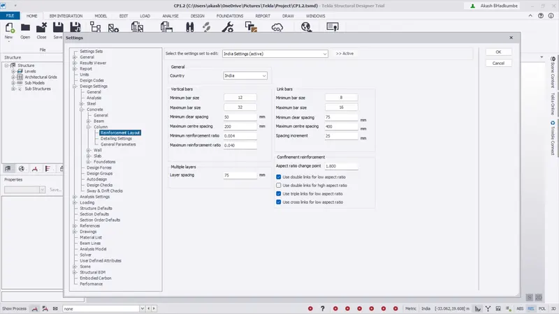
6. Check the reinforcement settings for pedestal columns.
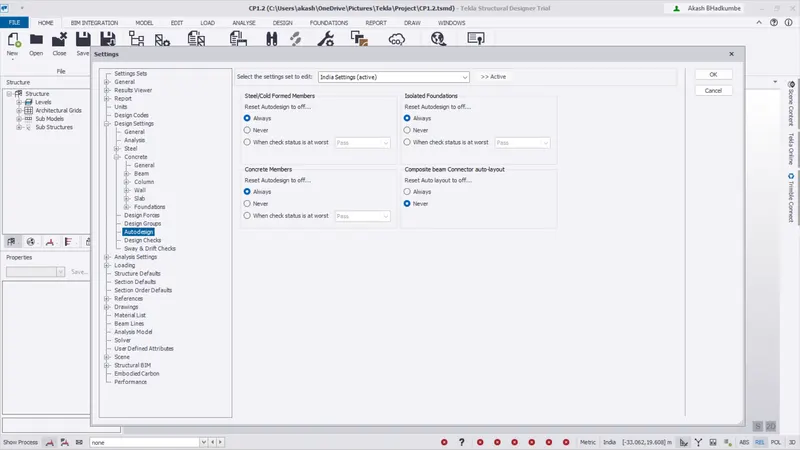
7. Check that the autodesign is off.
a. If autodesign is on:
- For steel members, you select the desired the section property. TSD then provides the suitable size for the selected section type.
- For concrete members you assign the desired section size. TSD then automatically provide a suitable reinforcement configuration.
b. If autodesign is off:
- You assign the desired section size (for steel members), or secction size & reinforcement (for concrete members). Then the TSD determines the reinforcemnt or section property is suffient.
8. Go to material and Select the material for Steel sections & concrete mebers.
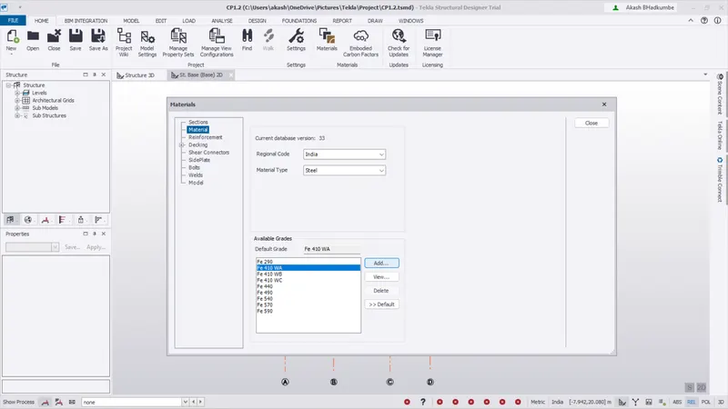
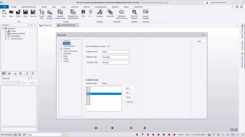
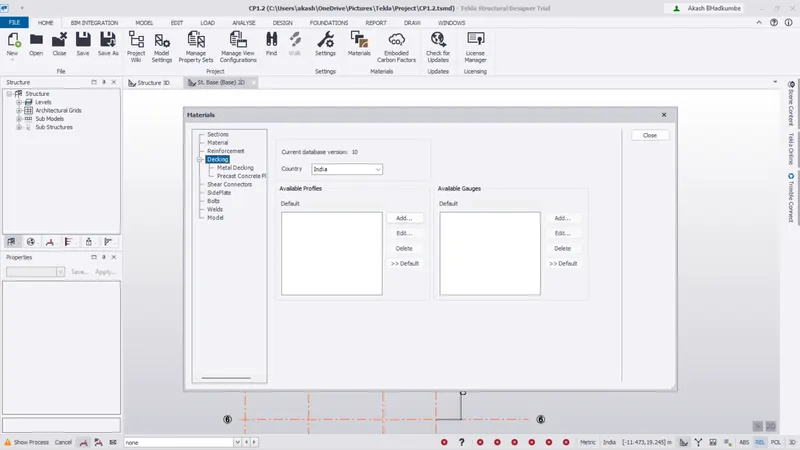
Step 2:
1. After selection of material. Use the Construction levels & Grids created in the Assignment No.1 & Challenge No.1.
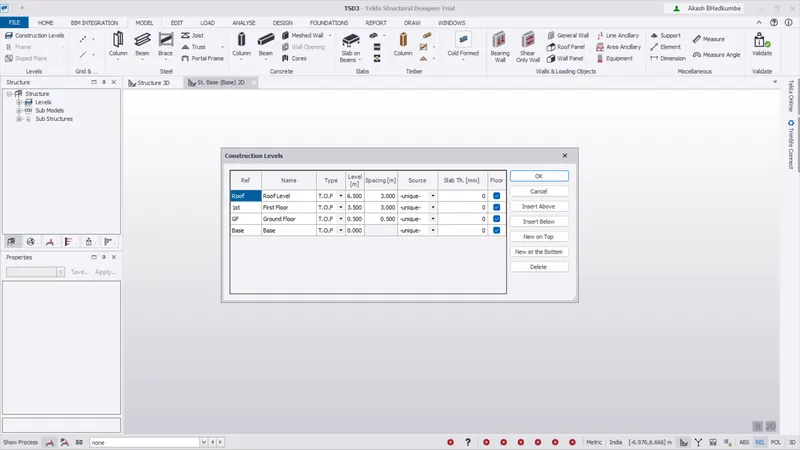
2. To create properties for pedestal column.
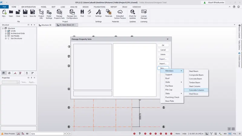
a. Go to Home -> Project -> Manage Property Sets. Click on New -> Members -> Concrete Column.
b. Create a new property rename it as PD1 & make changes as given in image below. Make sure that autodesign is off.
c. Create a column of Size 400x600mm with grade of concrete is M25.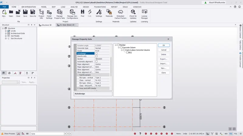
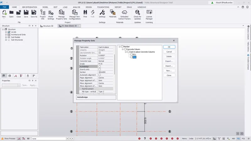
d. Follow the same procedure and create a column of size 400x800mm & rename it as PD2.
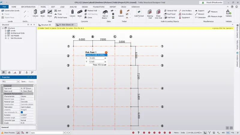
3. Select the size of pedestal column & click on intersection of grid the column will be created automatically. Make sure that the column will be create from Base Level to Ground Floor Level.
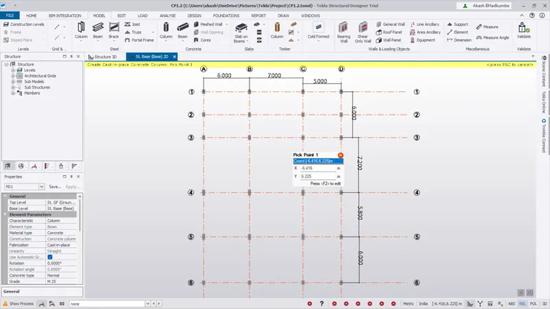
Result:
Pedestal Column create at Base Level upto Ground Floor Level.
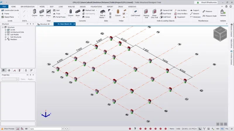
Q.2 Ans
Aim: Create Properties for stell columns and model columns in the grid created as per assignment 1.
Procedure:
Step 1:
1. To import the steel section properties. Again go to Home -> Manage Property sets -> New -> Members -> Steel Columns.
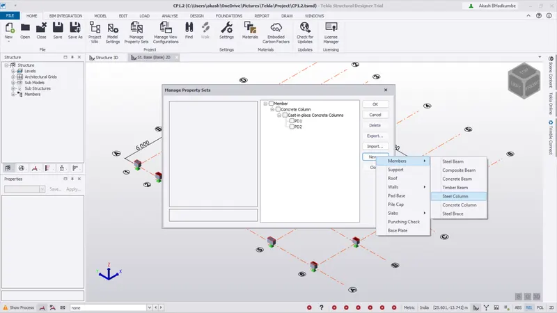
2. Rename property name as C1 and select the section property of column as ISMB350. Make sure that autodsign is off.
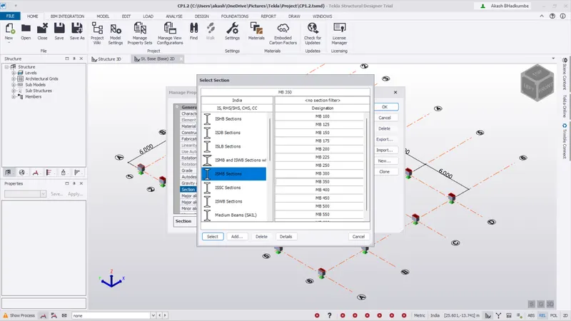
3. Repeat the procedure and create column C2 with section property ISMB 500.
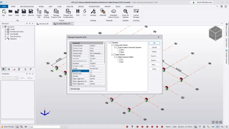
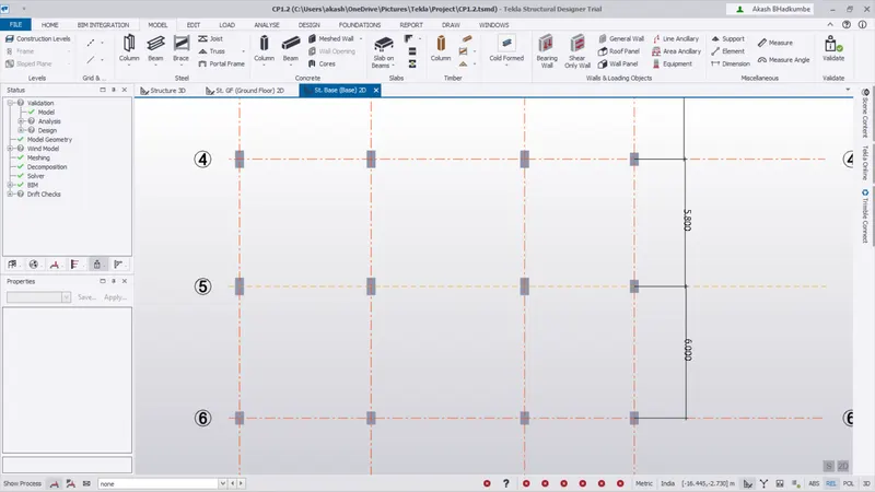
Step 2: Go to Model -> Steel -> Column. Select the section property as C1 click on the grid line intersection or click on pedestel column.
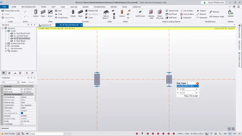
Step 3: Create the column on all the pedestals.
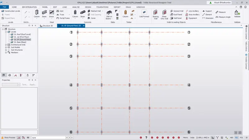
Result: The colums are created on all the grid intesection.
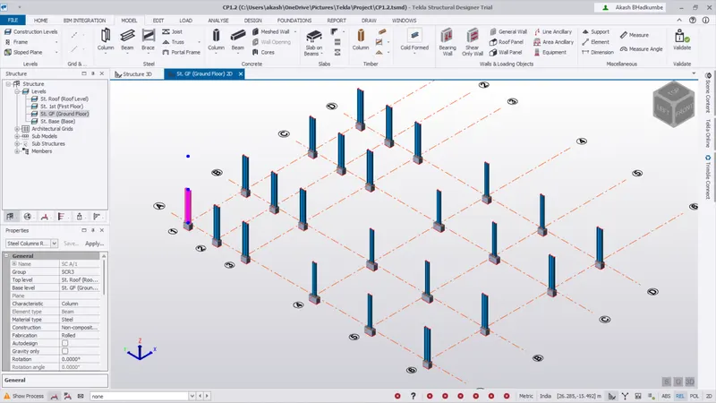
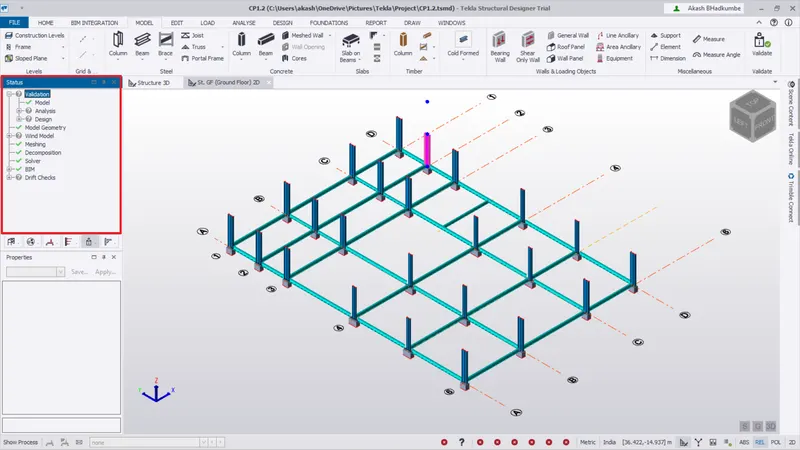
Check hense Ok. That there is no error in placing columns.
Q.3 Ans
Aim: Create beam property and model primary and secondary beams on the ground floor.
Procedure:
Step 1:
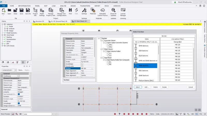
1. To model a primary and secondary beam. Import the section property of ISMB 250 as Primary beam & ISMB 300 as Secondary beam.
2. Go to Home -> Model property set -> New -> Member -> Steel Beam.
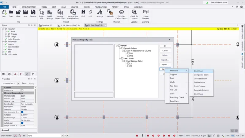
Step 2: Rename the Beam properties B1 Primary beam of ISMB 250 Section property & B2 Secondary beam of ISMB 300 section property.
Step 3:
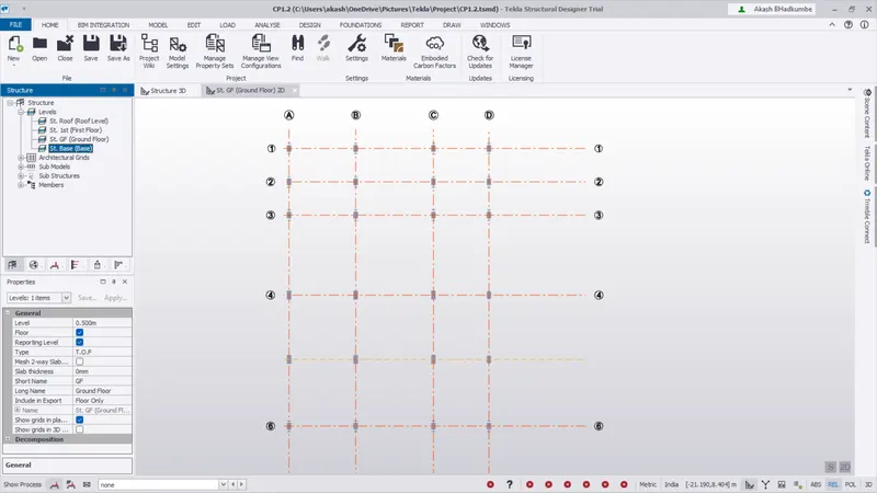
1. To model the beam on ground level go to Level -> Construction level -> Ground Floor Level.
2. To model beam go to Model -> Steel -> Beam. Select the property and select the start and end point of beam.
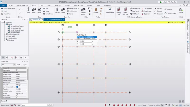
3. Create all the beams one by one and complete the beam modelling at ground floor level.
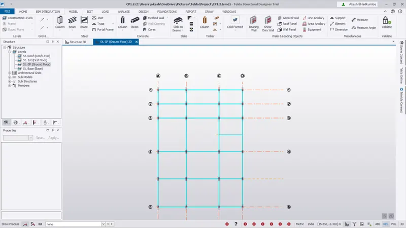
Result : All the beams are created at ground floor level with Click on validate it show the error in beam model placing.