Modelling of 25 storey building with the specified properties using ETABS
Aim: ETABS modelling of a 25 storey building
Procedure:
Step 1: Analysis of Model.
a. Material Data:
- Concrete Grade: M30
- Grade of Steel: Fe415
b. Properties:
- Beam: 300 x 400 mm
- Column: 800 x 800 mm
- Slab: 150 mm
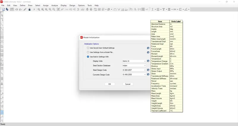
1. Create a Model with following initialization:
- Display Unit: Metric SI
- Steel Section Database: Indian
- Steel Design Basecode: IS 800:2007
- Concrete Design Code: IS 456:2000
2. Specify the following in model:
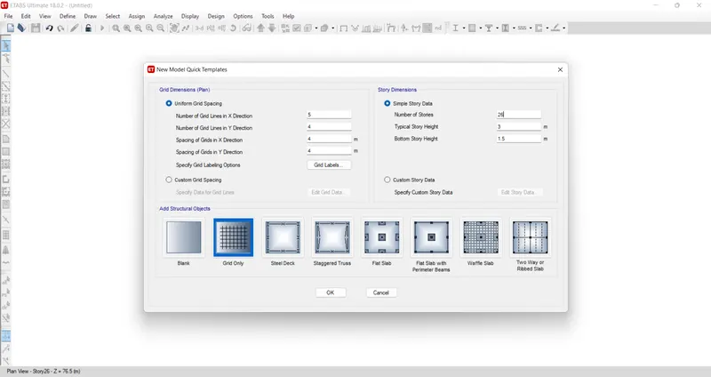
a. Grid Spacing:
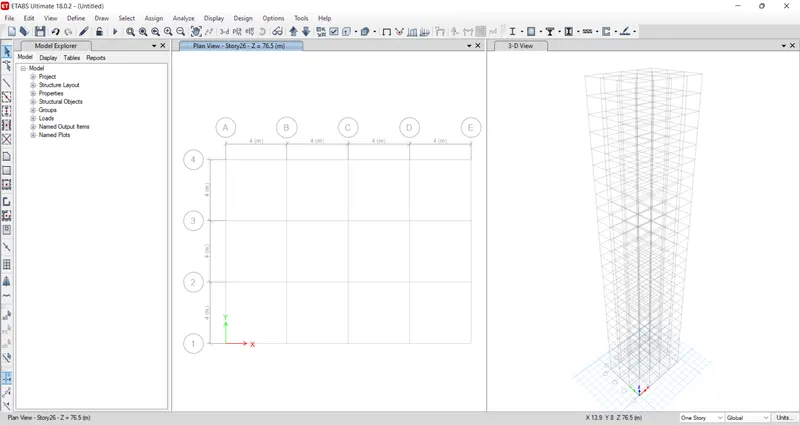
- Number Grid Lines in X-Direction: 5
- Number Grid Lines in Y-Direction: 4
- Spacing of Grid in X-Direction: 4
- Spacing of Grid in Y-Direction: 4
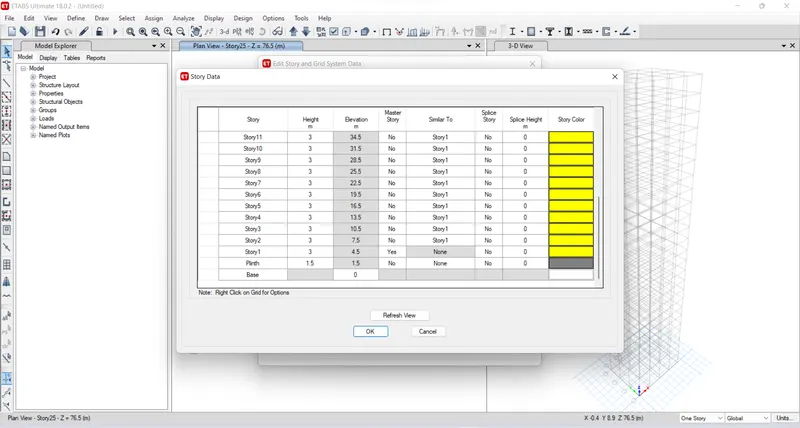
- Number of Stories: 26
- Typical Story Height: 3
- Bottom Story Height:1.5
3. Define the properties:
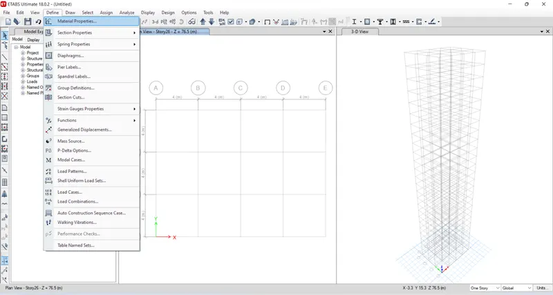
- Go to Define -> Material Properties -> Add new material.
- Create the matrial for concrete as shown in figure.
- Add the grade of Concrete as M30. Click Ok.
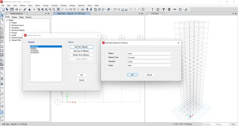
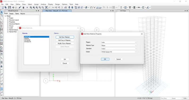
- Repeat the same Go to Define -> Material Properties -> Add new material.
- Create the matrial for Steel as Rebar HYSD 415 as shown in figure. Click Ok.
4. Add section properties:
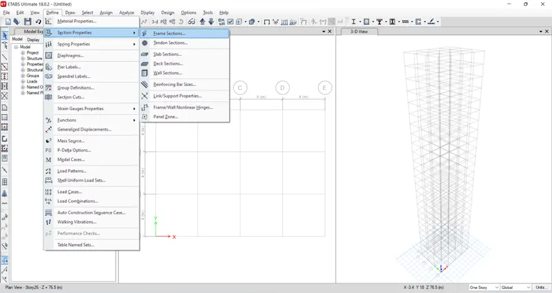
- Go to Define -> Section Properties -> Frame Section -> Add new Property.
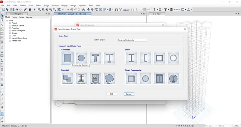
- Select Concrete Rectangular Shape.
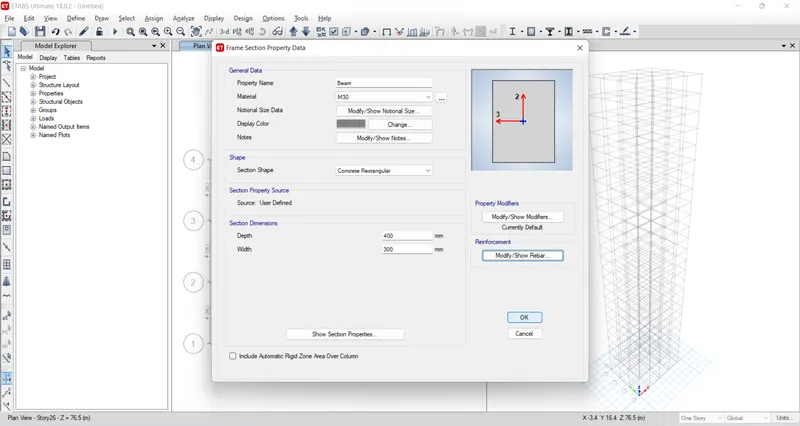
- In the Frame section property data
- Property Name: Beam
- Material: M30
- Section Dimension: Depth=400mm, Width=300mm.
- Repeat the same to define section property for column as follows.
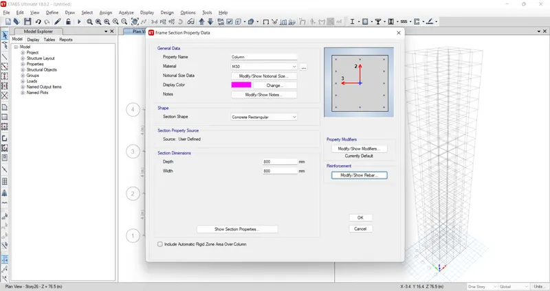
- Property Name: Column
- Material: M30
- Section Dimension: Depth=800mm, Width=800mm.
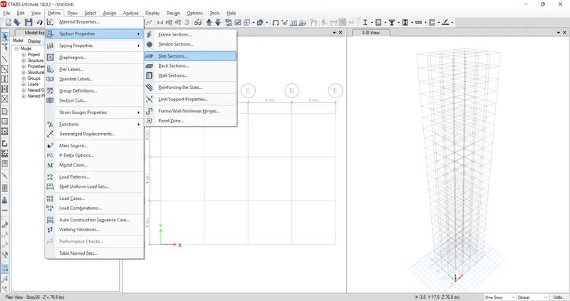
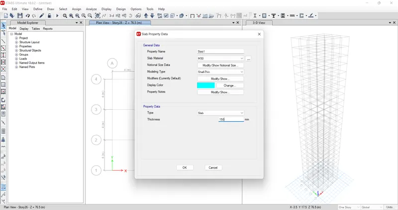
- Define -> Section Properties -> Slab Section -> Add new property.
- In slab property data set the following.
- Property Name: Slab
- Material: M30
- Section Dimension: 150mm.
5. Go to View Menu -> Set Plan View
6. Go to Draw Menu -> Draw Beam/Columns/Brace Objects -> Quick Draw Columns.
- In the properties of the Object, Set the property as Column.
- Using select object cursor, drag windows in such a way it is not creating the column in the bottom right corner of the model.
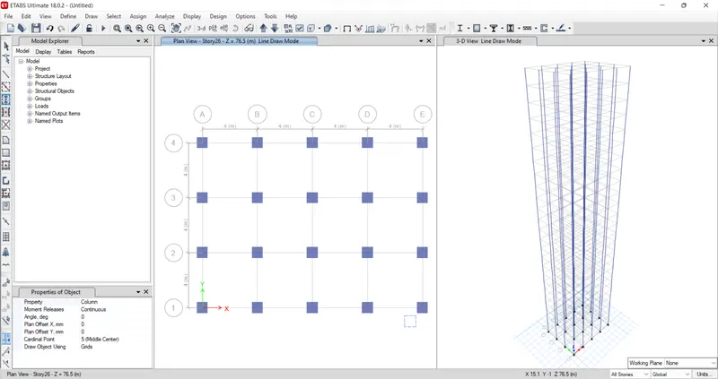
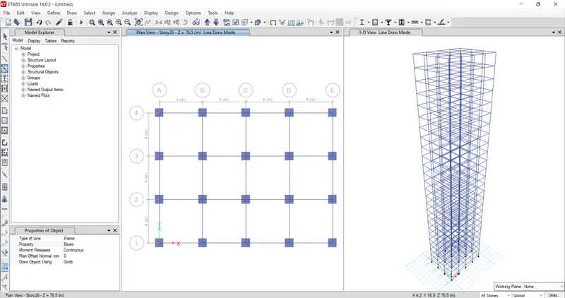
7. Go to Draw Menu -> Draw Beam/Columns/Brace Objects -> Quick Draw Beam/Columns.
- In the properties of the Object, Set the property as Beam.
- Using select object cursor, drag windows in such a way it is not creating the column in the bottom right corner of the model.
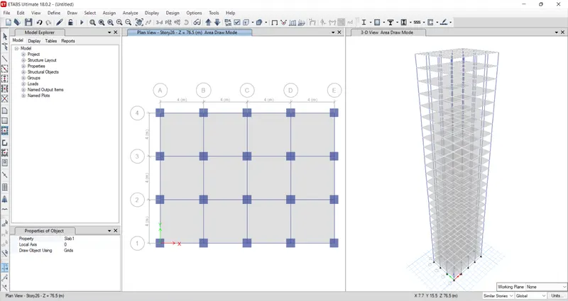
8. Go to Draw Menu -> Draw Floor/Walls Objects -> Quick Draw Draw Floor/Walls.
- In the properties of the Object, Set the property as Slab.
- Using select object cursor, drag windows in such a way it is not creating the column in the bottom right corner of the model.
- The slab object is automatically modeled.
9. Select Bottom joints.
- Go to Assign -> Joints -> Restrains.
- Select and apply pinned restrains.
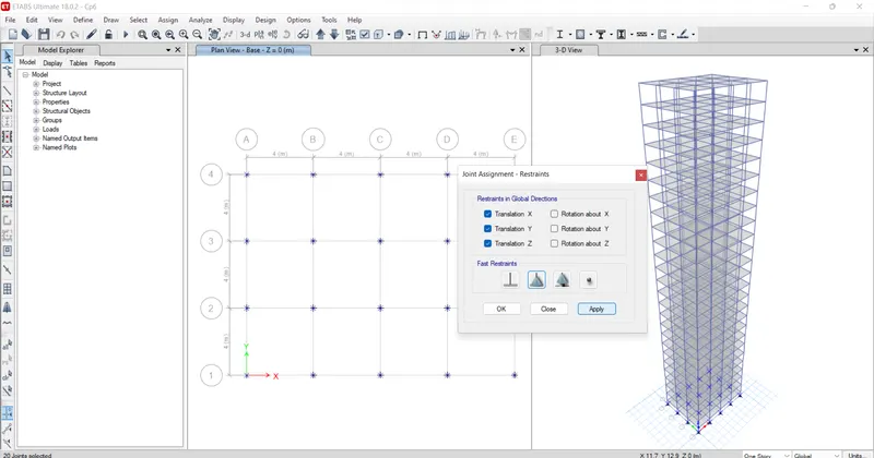
10. Define Load Patterns:
- Go to define -> Load Patterns -> Dead Load & Live Load.
- Create a Wall Load as Super Dead Load.
- Create a Seismic load in X & Y Direction. Provide IS Code 1893.
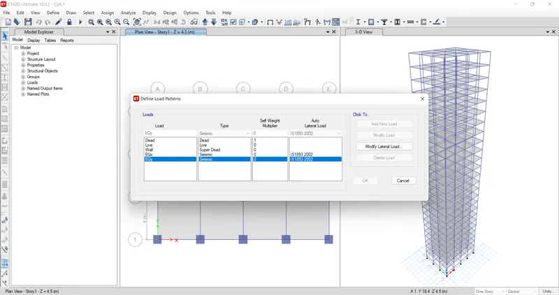
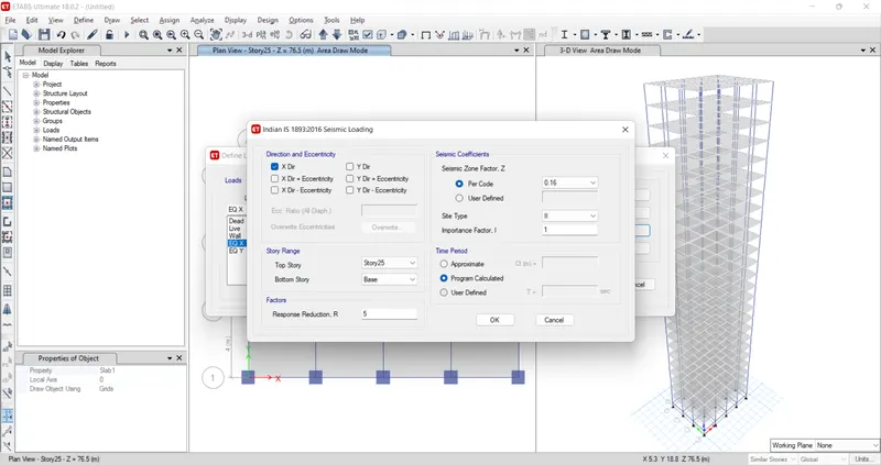
- Select X Direction Seismic load & go to Modify Load.
- Provide Direction & Eccentricity on X Direction.
- Zone Factor: 0.16
- Story Range: Bast to 25 Story.
- Response Reduction Factor: 5
- Importance Factor: 1.
- Time Period: Pragrame calculated.
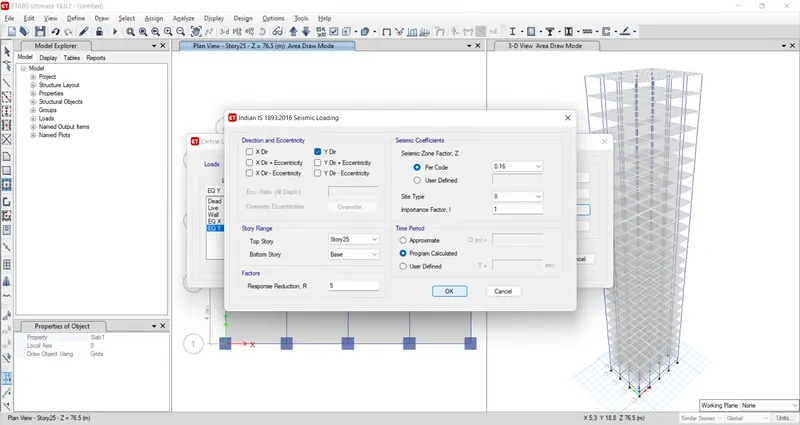
- Select Y Direction Seismic load & go to Modify Load.
- Provide Direction & Eccentricity on Y Direction.
- Zone Factor: 0.16
- Story Range: Bast to 25 Story.
- Response Reduction Factor: 5
- Importance Factor: 1.
- Time Period: Pragrame calculated.
- We have to define the mass sourse data in Seismic load with respect to Dead, Live & SuperDead Load.
- Go to Define -> Mass Source Data -> Modify data.
- Mass Source: Specified load pattern.
- Add Mass multiplier for Load pattern: Dead Load=1, Wall Load=1 & Live load= 0.25.
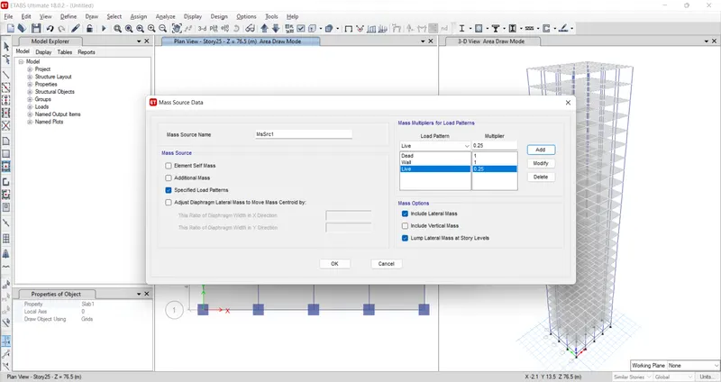
Step 2: Assigning of Load:
1. Live Load on Floors= 3kN/m.
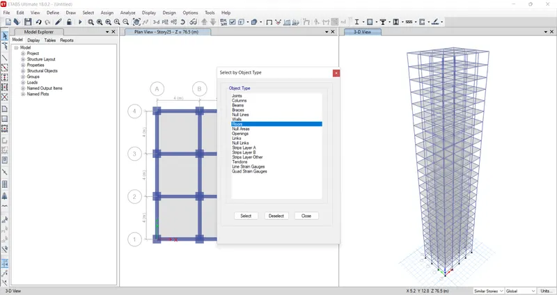
- To select all the floors & types go to select -> Object type -> Floors.
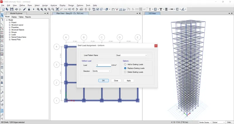
- Go to Assign -> Shell Load -> uniform.
- Load pattern Name: Live
- Uniform Load: 3
- Direction: Gravity.
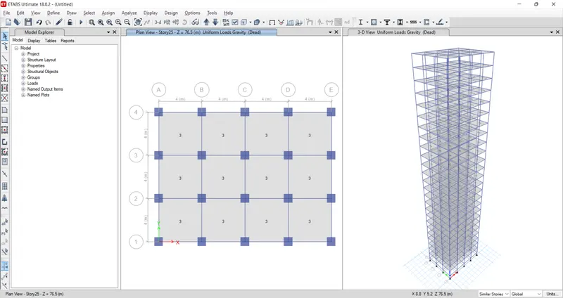
- The floor load of 3kN/sq.m is added on all floors.
2. Dead Load on Beams= 10kN/m.
- To select all the beams & types go to select -> Object type -> Beam.
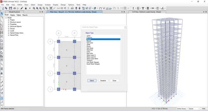
- Go to Assign -> Frame Load -> Distributed.
- Load pattern Name: Wall
- Load Type Specification: Force
- Direction: Gravity.
- Uniform Load: 10.
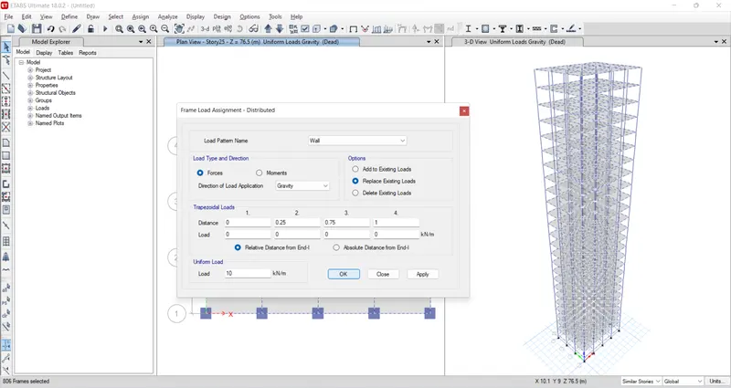
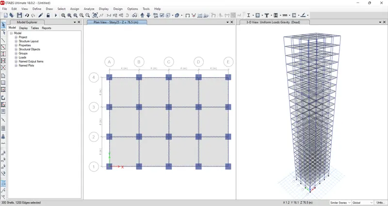
- The Beam load of 10kN/m is added on all Beams.
Step 3: Add diaphragms.
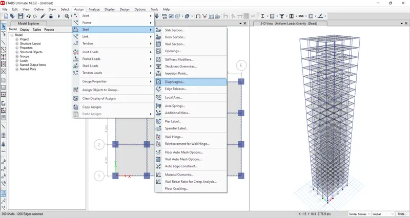
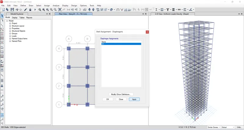
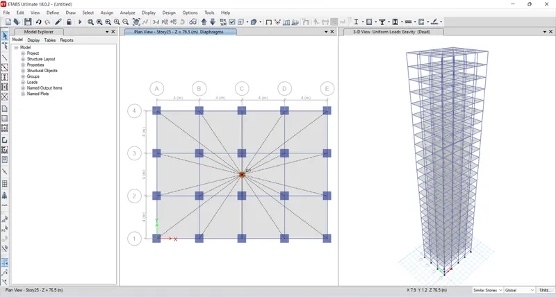
- Go to assign-> shell -> Diaphragms.
- Select the D1 and diaphragms will be added on the all floors.
Generate Check model:
- Go to Analyze -> check model.

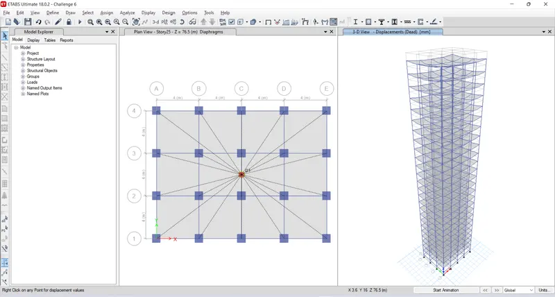
Go to Analyze -> Run Analysis.
Results:
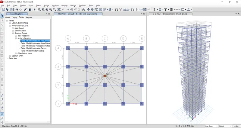
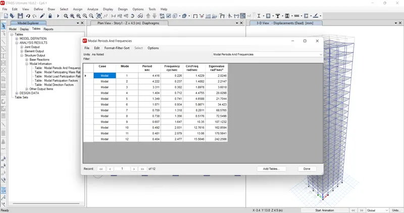
- Go to model Explorer Display>show tables>Analysis results>Structure ouput>Modal information>modal periods and frequencies.
- The time periods for fundamental mode-1Y direction and findamental Mode -1X direction are noted from the table and are as follows:
- Tx1=4.416 seconds and Ty1=4.222 seconds
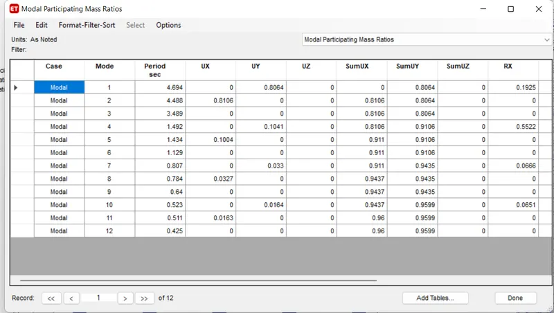
- Display>show tables>analysis results>structure output>modal information>modal participation mass ratios.
- From the table the natural time period for mode-1 and torsional DOF are noted as follow:
- Tx1=4.694 seconds Ty1=4.488 seconds Txy1=3.489 seconds
- So from the results it is clear that the torsional time period is less than two translational time period as required by IS 1893 provision table 5.
- When we add the three mode mass ratios we get 0.9044 which menas first three modes of seismic oscillation contribute more than 65% of building weight as per ETABS anaysis.
- The storey drift for serviceability Base shear case(EQX or EQY) is tabulated from the following tool path.
- Go to display>Storey response plot
- Keeping load case to EQY and switching to max story drift the maximum drift value noted is 0.0000072.
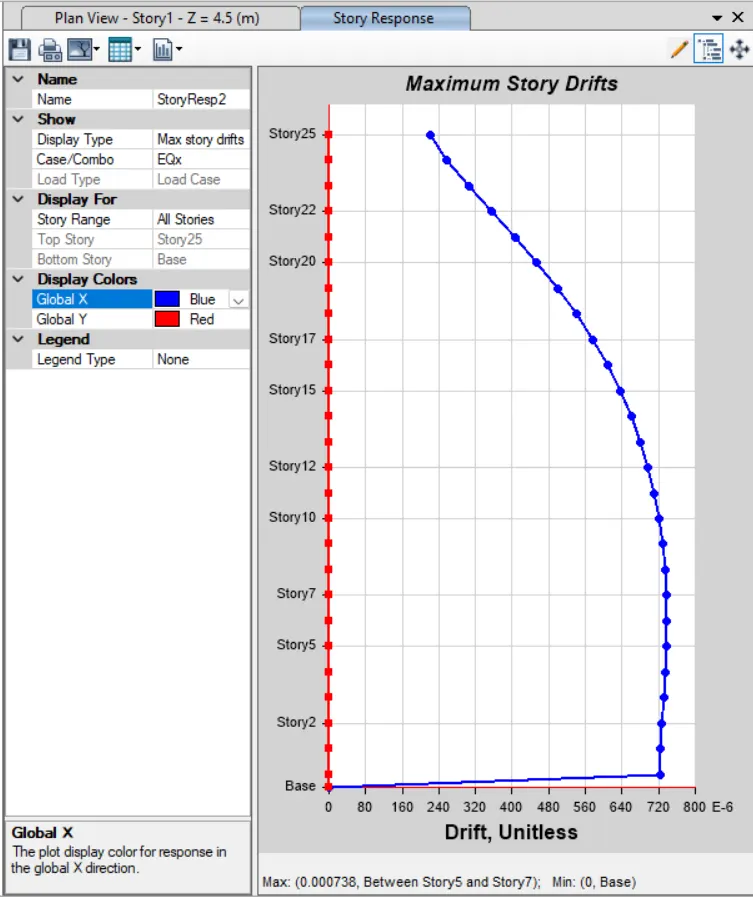
- So as per the clause 7.11.1.1,the maximum inter storey drift is milited to 0.004 for each storey height.But our value is 0.0020 which is within the code limits.