Creating Levels, Grids, Layout and model elements for a residential unit using REVIT
Q.1 Ans
1. Building Information Modeling:
i. BIM is a visual representation of the physical and functional characteristics of a facility from inception onwards. As such, it serves as a shared information repository for collaboration throughout a facility's life cycle.
2. Features of BIM:
- Easy access to information
- Making the process more expensive
- Comprehensive view of the project
3. Benefits of BIM:
- Complete representation
- Instant Updates
- Time constraint
- Resourse tracking
Q.2 Ans
Step 1: Open the previous drawing.
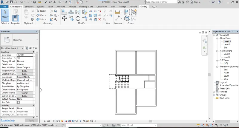
Step 2: Go to insert tab and go to load panel and load family.
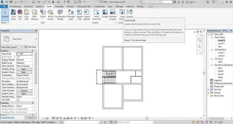
Step 3: The library will be open.
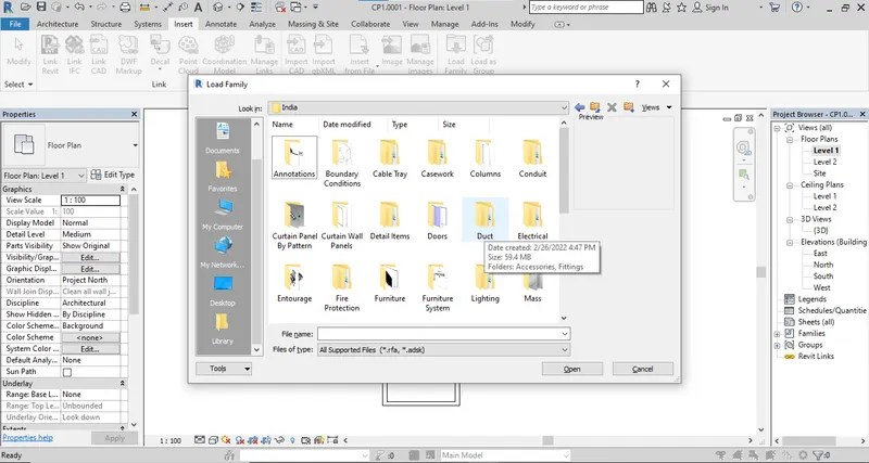
Step 4: Go to door family. The Door categories will be open.There are Commercial, Residential & Hardware are the categories of Door.
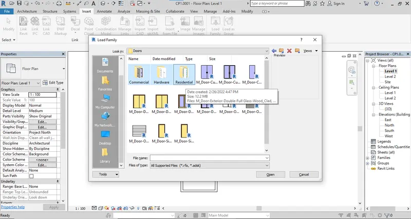
Step 5: I am selecting the residential categories so the family of door will be open.
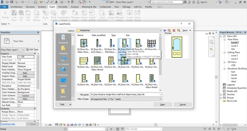
Step 6: Select any type of Door and select the size of door which you required.
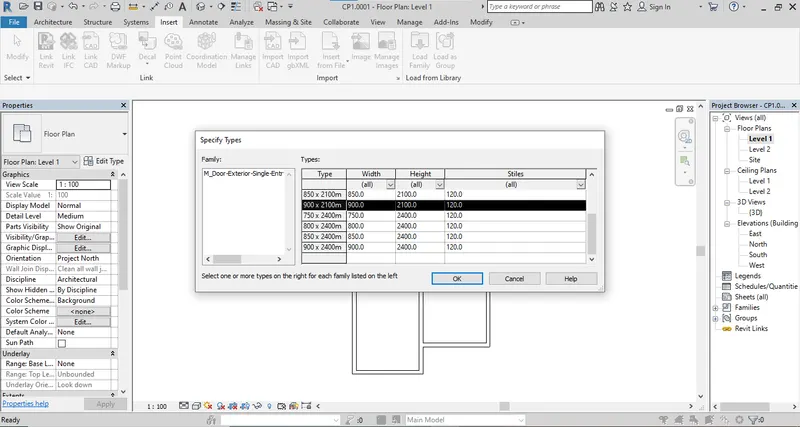
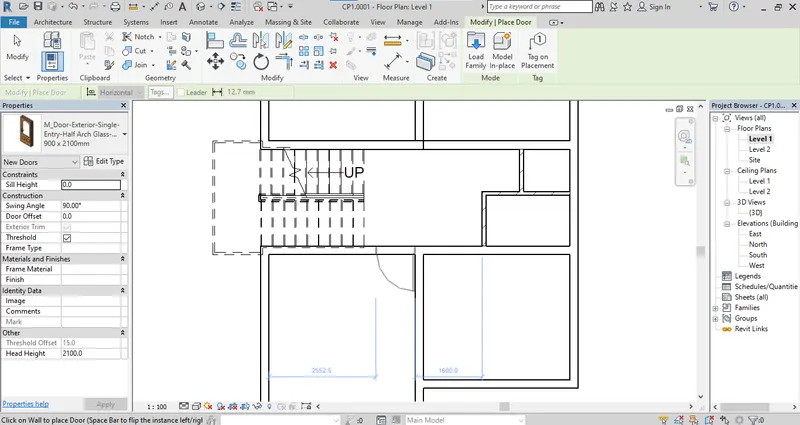
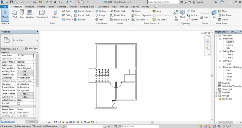
Step 7: Go on size of wall and provide wall where required.
Q.3 Ans
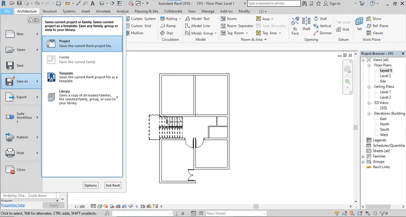
Step 1: As we completed the drawing as per the question we have to save the file.Go to File menu.
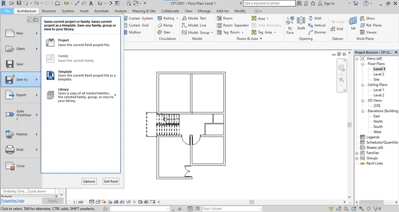
Step 2: Go to Save As and then save the file as project.
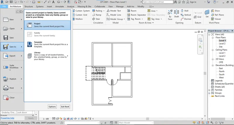
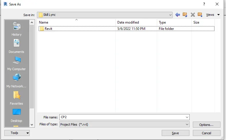
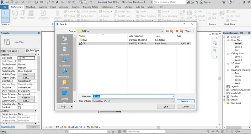
Step 3: Provide a proper name to the project file.
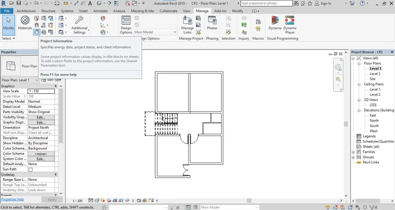
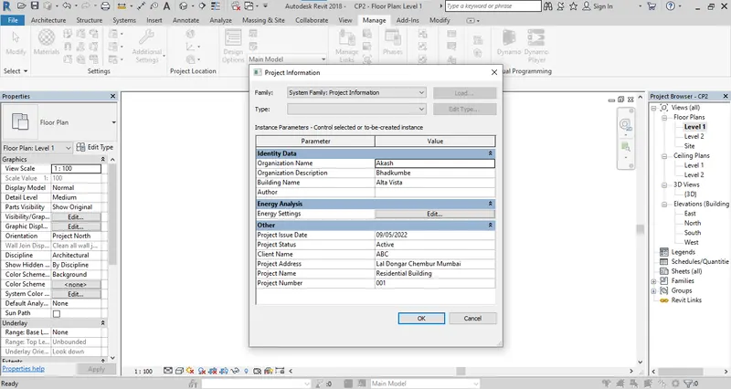
Step 4: After providing the name to the project file. Go to manage tab and tab of the project information.
Step 5: Now you can provide the provide information manually.
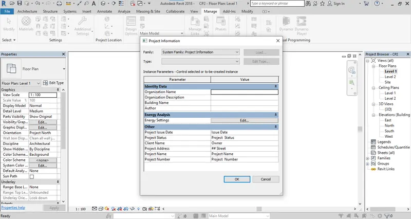
Step 6: Provide the information given below.
Step 7: To create maximum backup of file Fo to file menu then go to save as then project.
Step 8: Go to option.
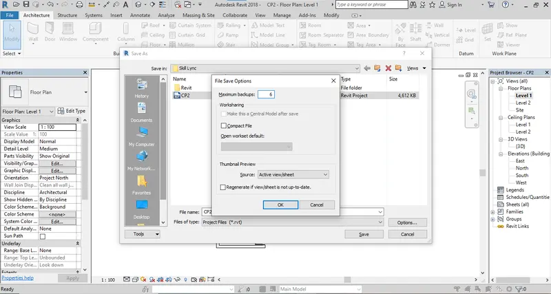
Step 9: Select maximum backup. I am creating 6 backups. You can provide from 1-99. Save the file.
Q.4 Ans
Step 1: Create a new file with the architectural template.
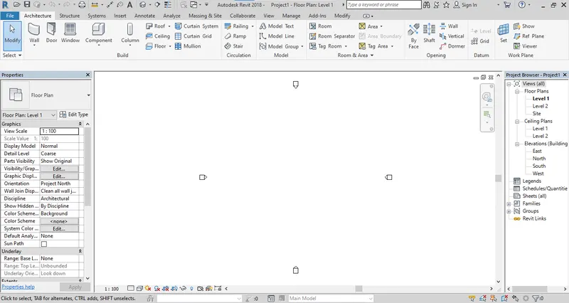
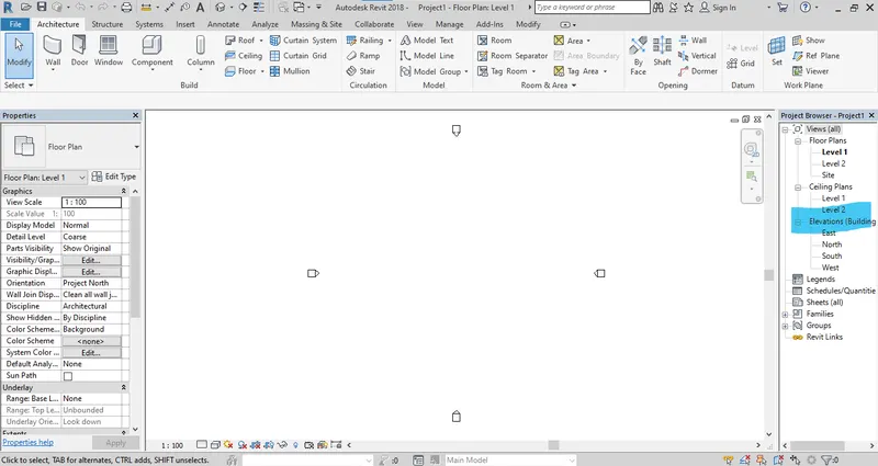
Step 2: levels are not visible in any plan other than the Elevation plan. So go the elevation plan to draw the levels.
Step 3: As you enter in the elevation view the levels will be visible.
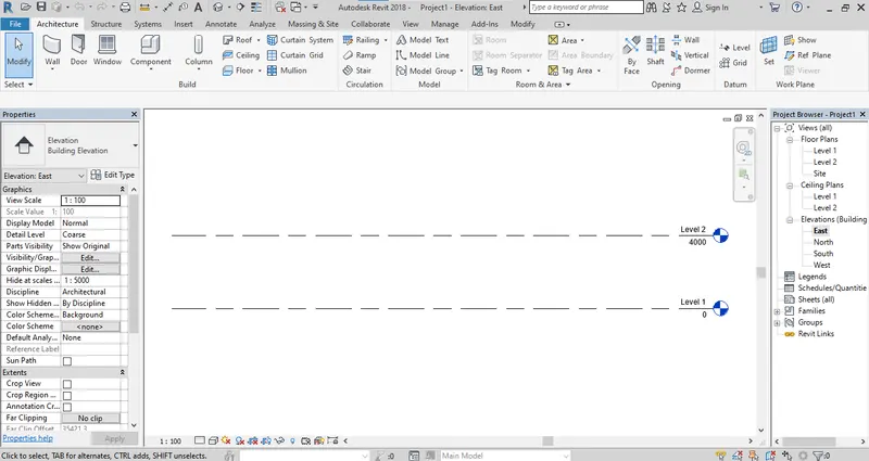
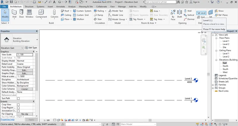
Step 4: There are two existing layer in elevation. To add more layer select level option datum panel or use the shortkey "LL".
Step 5: There are two methods to draw the levels.
a. Line b. Pick a Line
I am using the Pick a Line method and drawing the levels.
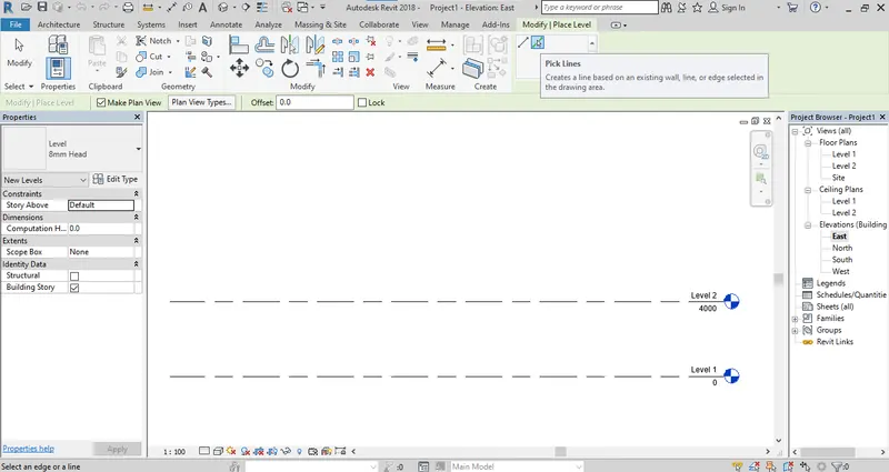
Step 6: Use the offset of 10' Distance and draw levels.
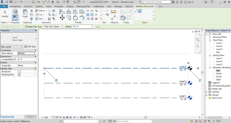
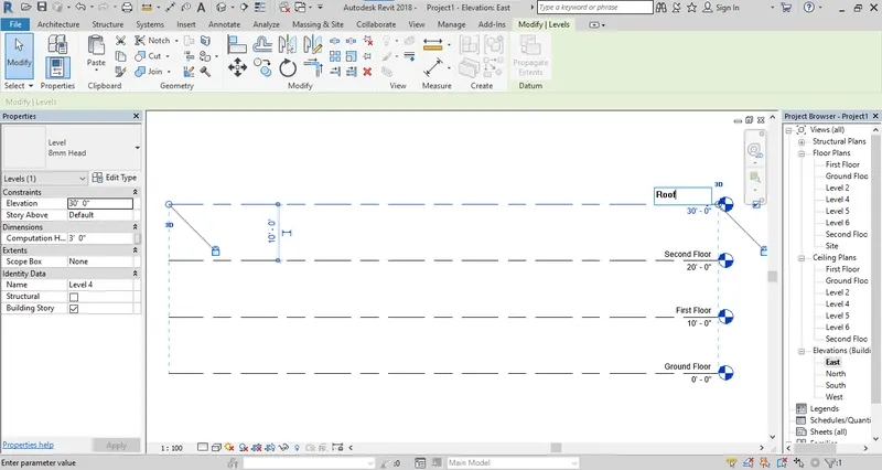
Step 7: As you draw the level rename the levels.
Step 8: Double click on First floor and go to plan view to draw grids.
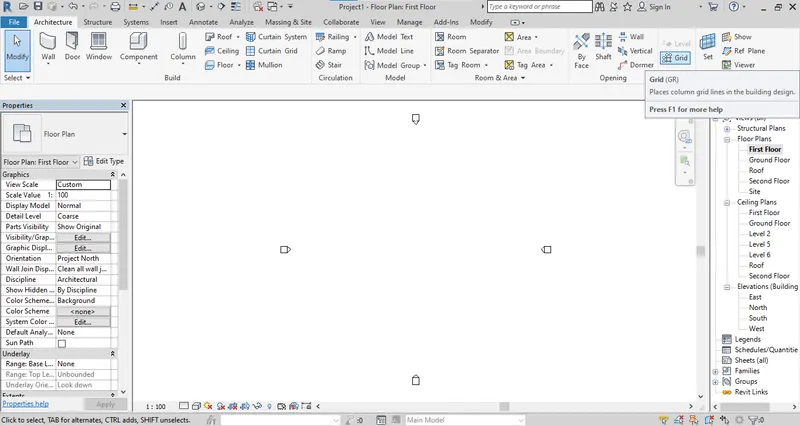
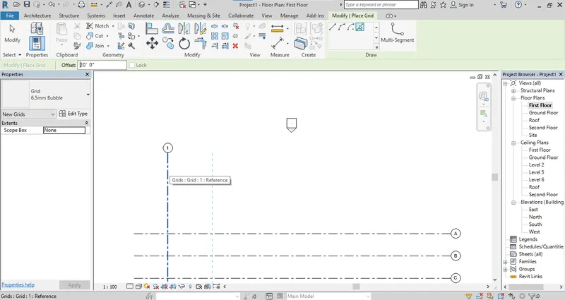
Step 9: Now again go to datum panel and draw the grid or use the shortkey "GR".
Step 10: Go to grid option. There are four method to draw the grid. 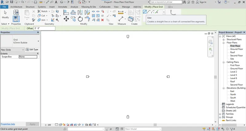
Step 11: Draw the grid in transeverse direction and name it as "A".
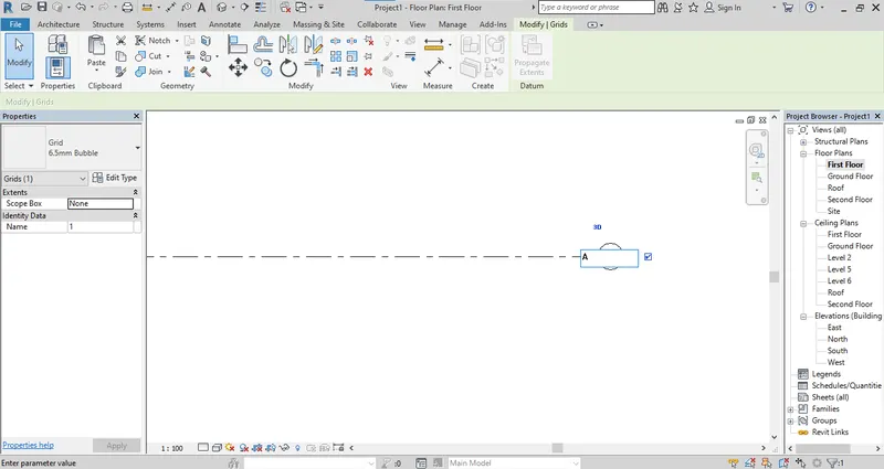
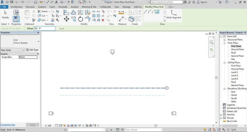
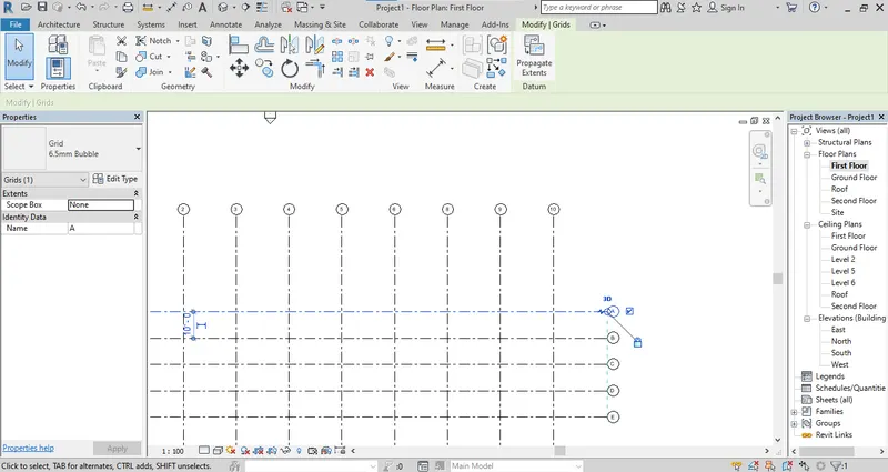
Step 12: Use the Pick a Line method and provide a offset of 10' to draw grids.
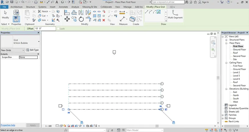
Step 13: Repeat the procedure and draw longitudinal grids in 1 to 10 with 20' spacing.
Q.5 Ans
Step 1: Open the file with architectural template.
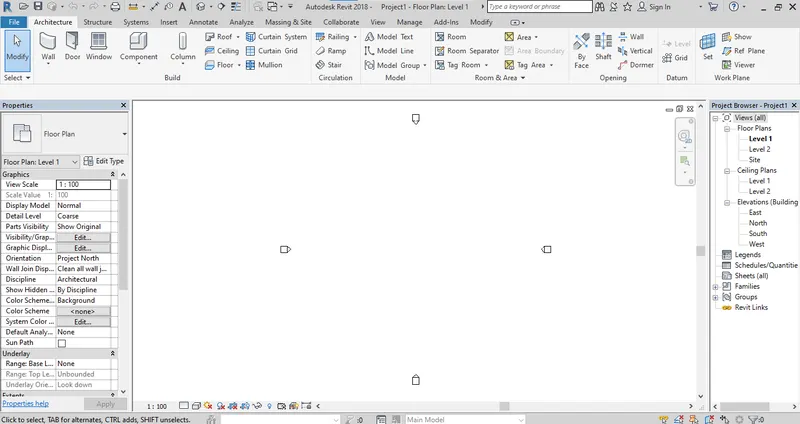
Step 2: Go to elevation and set the levels for height of structure. I am providing 3000mm height.
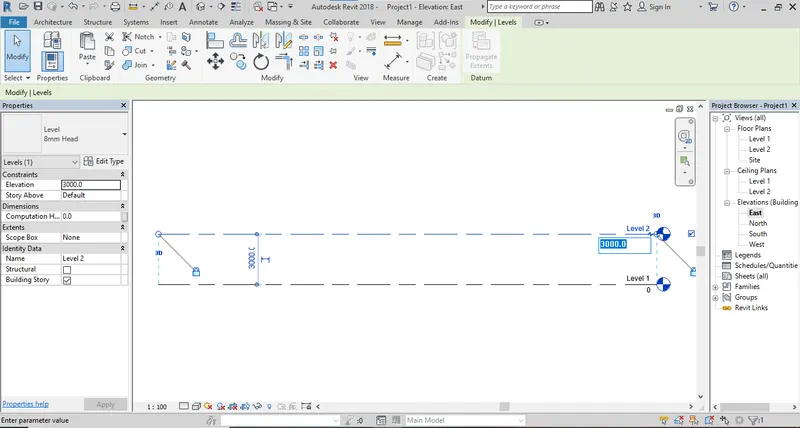
Step 3: Select a wall command to draw the walls or use "WA" shortkey.
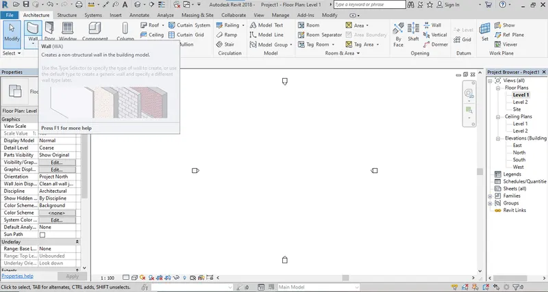
Step 4: Go to Floor plan at "LEVEL 1" to draw layout.
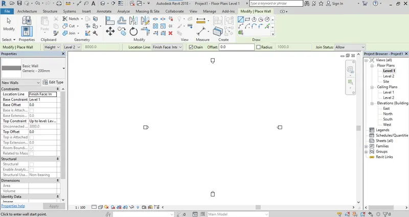
Step 5: I am using rectangular command to draw a room with 300mm wall main wall.
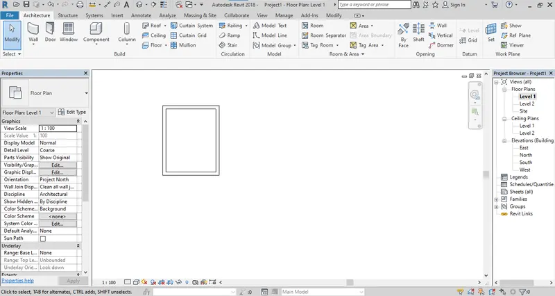
Step 6: Creating another room beside this.
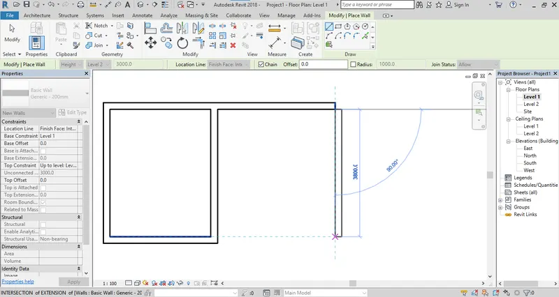
Step 7: Use 150 mm wall for bathroom and w/c.
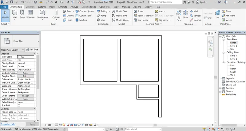
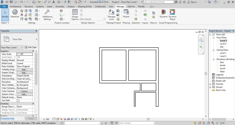
Step 8: Use the boundary wall of 300 mm thickness and draw another rooms besides this.
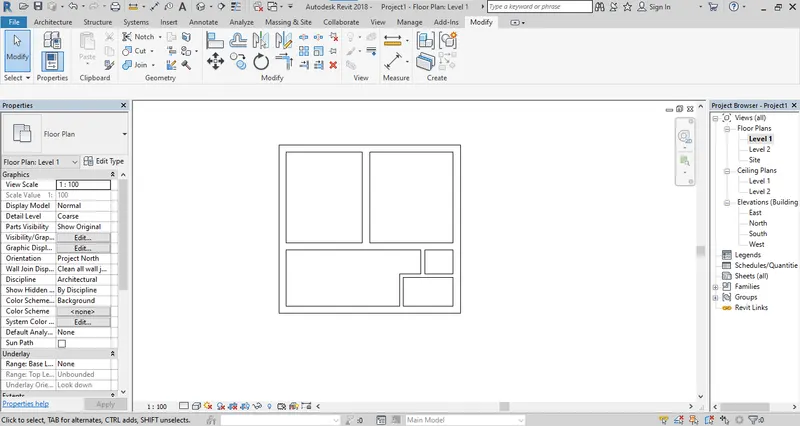
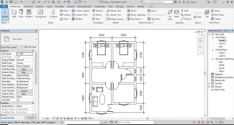
Step 9: The plan is ready now.
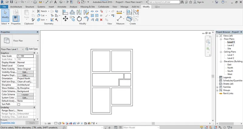
Q.6 Ans
Step 1: Go to annotate and dimension panel and select the Aligned.
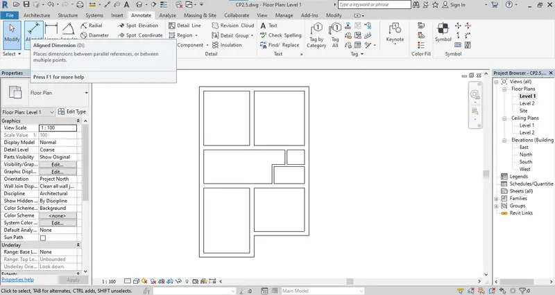
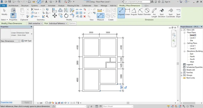
Step 2: I am selecting centre to centre dimension of every room.
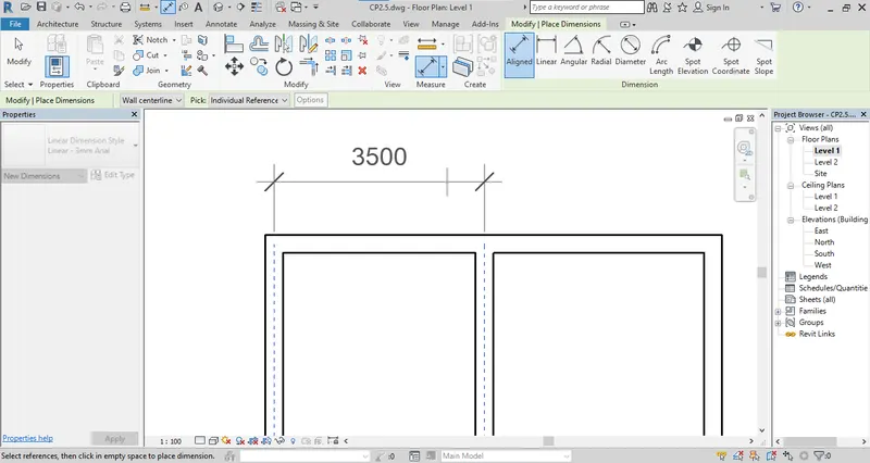
Step 3: Select the dimension of every room.
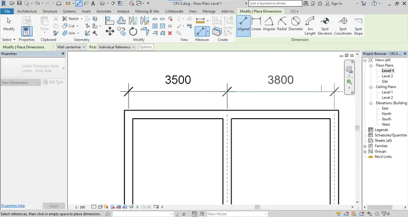
Step 4: Select the dimension of every room one by one.
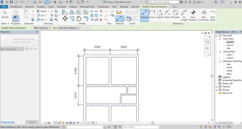
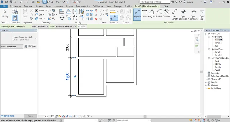
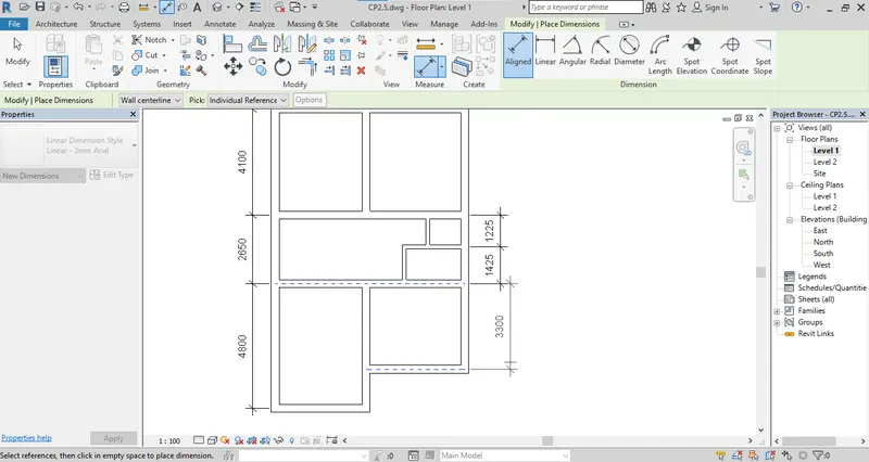
Step 5: Dimension will be provided to all the room.
Q.7 Ans
Step 1: Go to doors from architectural build panel and select doors for the layout.
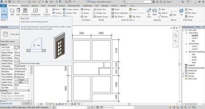
Step 2: If ou need another typr of door go to load family and load the door family.
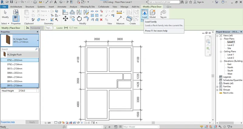
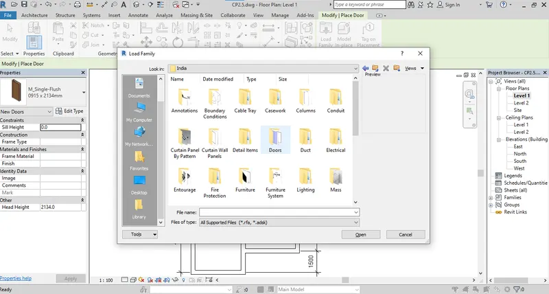
Step 3: I am going to residential category and selecting the Main door type and select th size of door. Provide at the opening.
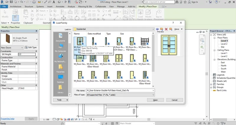
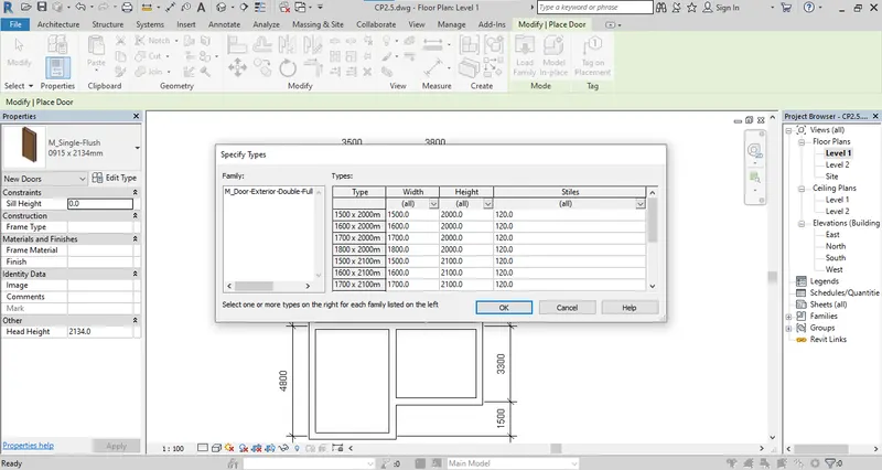
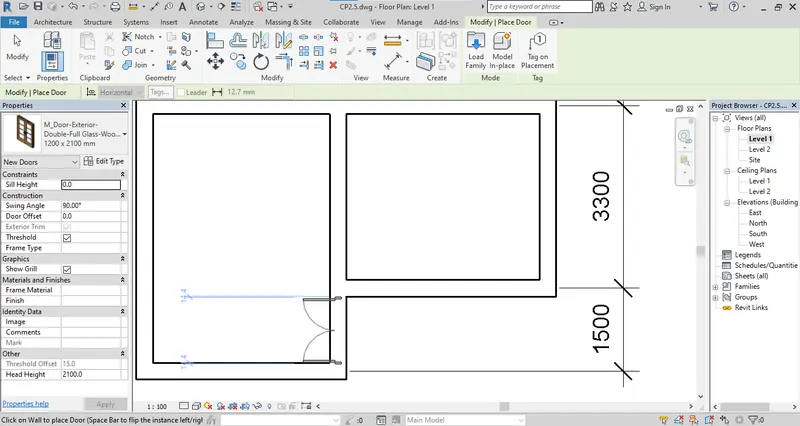
Step 4: Select another type of door fmaily for bed room and kitchen and bath.
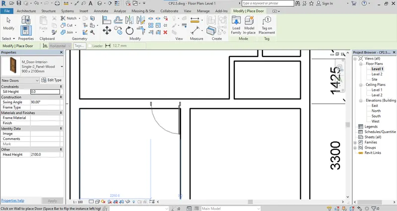
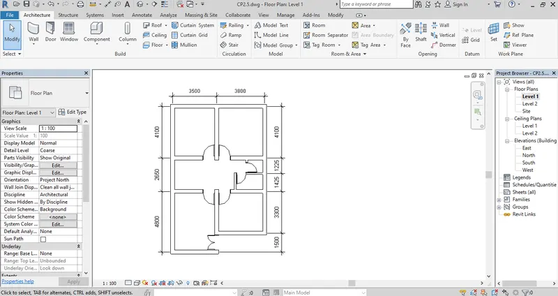
Step 5: Repeat the ame procedure for window and furniture provide the windows where required.
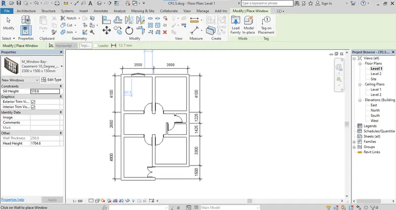
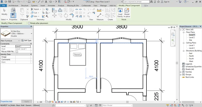
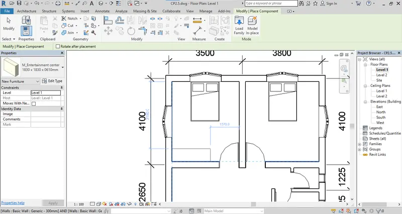
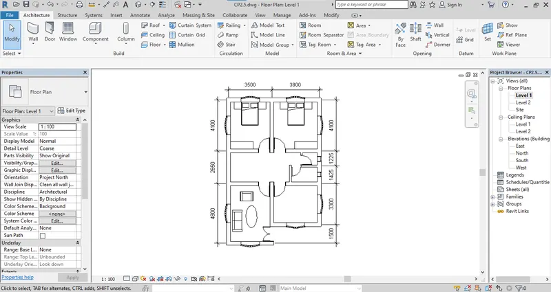
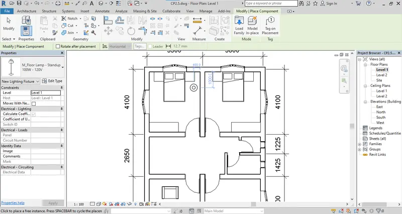
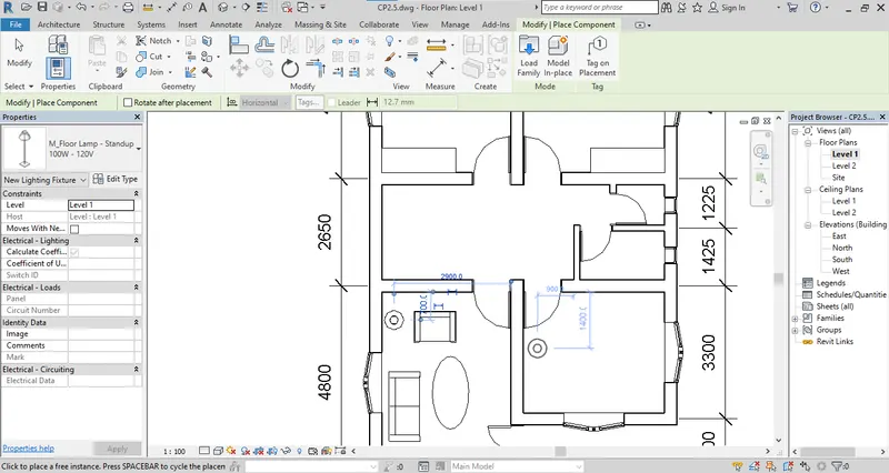
Step 6: After provision of furniture provide the lighting from lighting component and family.