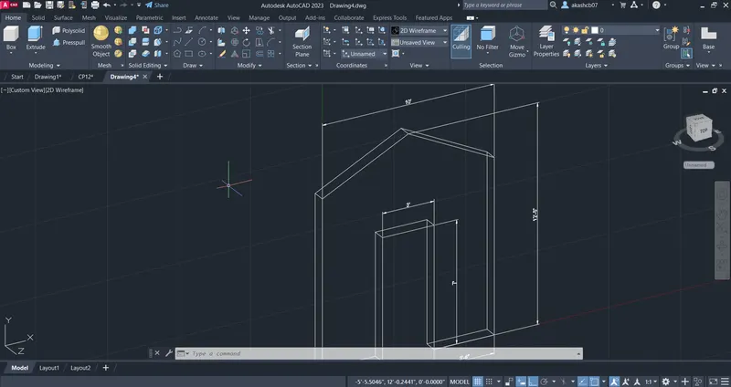
Creating various 3D Models like Furniture, Footing, Girder, Column drop with panel and Gable Wall in AutoCad
Q.1 Ans
Aim: Create a 3D Furniture use the dimension as given.
Procedure:
Step 1:
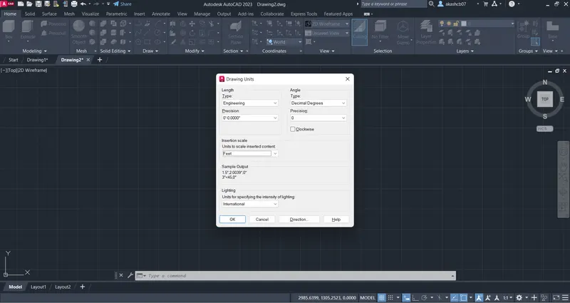
- Open the new AutoCAD file with imperical unit to provide the dimension in feet and inches.
- We have to create a 3D model of furniture so we have to change some setting for 3D.
- Go to Bottom toolbar -> Workspace -> Change the workspace from 2D drafting to 3D modeling. 3D interface will be open now.
- Create a front view of the table by using the "polyline" tool.
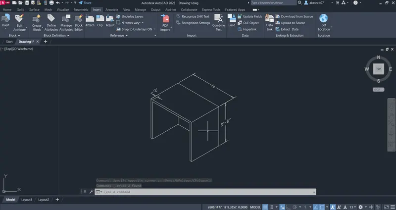
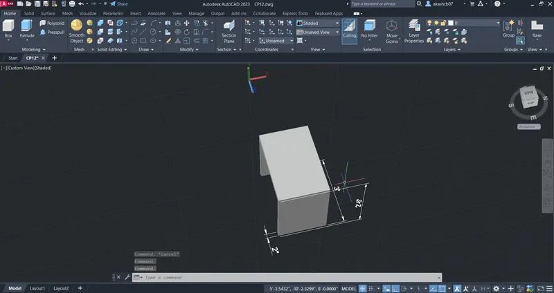
- Create a geometry of table of Height of 2'6" and 3' with 2" thickness.
- Go to extrude command and the extrude the created boundary.
- The table with extrusion is created.
- Go to Annotate -> Dimension and use the linear dimension tool to provide dimension.
- Use UCS command to change the axis of the dimension.
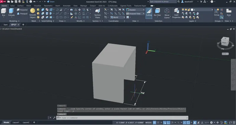
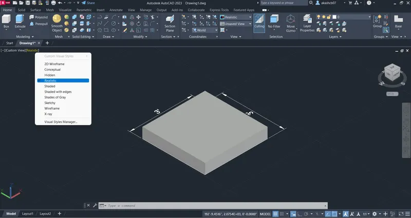
- Go to -> Custom view and change the view as Realistic, conceptual,hidden,shaded etc.
Result:
Q.2 Ans
Aim: Create a 3D model of isolated footing.
Procedure:
Step 1:
-
- Open the new AutoCAD file with imperical unit to provide the dimension in feet and inches.
- We have to create a 3D model of isolated footing so we have to change some setting for 3D.
- Go to Bottom toolbar -> Workspace -> Change the workspace from 2D drafting to 3D modeling. 3D interface will be open now.
- Create a front view of the isolated footing by using the "polyline" tool.
- Create a geometry ofisolated footing first we have to create a bottom portion of the footing.
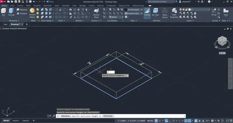
- Create a bottom portion of footing which has a size of 6" thickness as given we have assuming the width of footing as 3'.
- Go to extrude command and the extrude the created boundary.
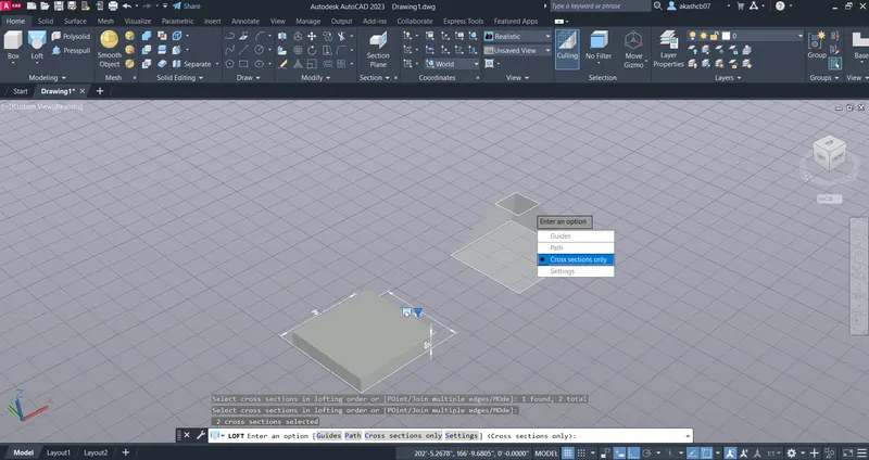
- Use a loft command and create a isolated part of footing which having top size of 1' x 1' and height 2'.
- Move the isolated part to rectangle portion.
- Go to Annotate -> Dimension and use the linear dimension tool to provide dimension.
- Use UCS command to change the axis of the dimension.
- Go to -> Custom view and change the view as Realistic, conceptual,hidden,shaded etc.
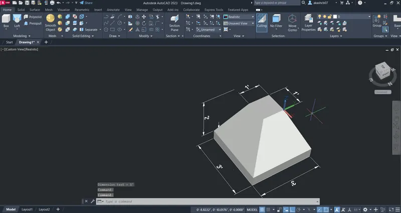
Result:
Q.3 Ans
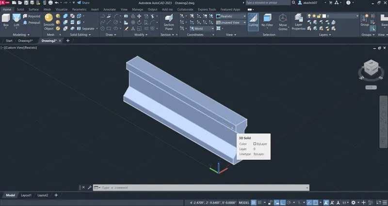
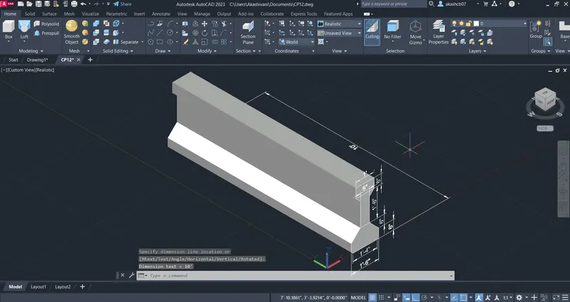
Aim: Create a 3d view of AASTHO type girder.
Procedure:
Step 1:
- Open the new AutoCAD file with imperical unit to provide the dimension in feet and inches.
- We have to create a 3D model of AASTHO girder so we have to change some setting for 3D.
- Go to Bottom toolbar -> Workspace -> Change the workspace from 2D drafting to 3D modeling. 3D interface will be open now.
- Create a front view of the girder by using the "polyline" tool.
- Create a geometry of girder as given in figure.
- Use the chamfer command to show the cutting edges.
- Go to extrude command and the extrude the created boundary.
- Provide the length to the girder 10' with extrusion is created.
- Go to Annotate -> Dimension and use the linear dimension tool to provide dimension.
- Use UCS command to change the axis of the dimension.
- Go to -> Custom view and change the view as Realistic, conceptual,hidden,shaded etc.
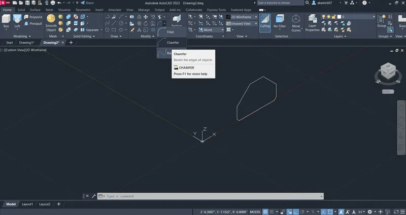
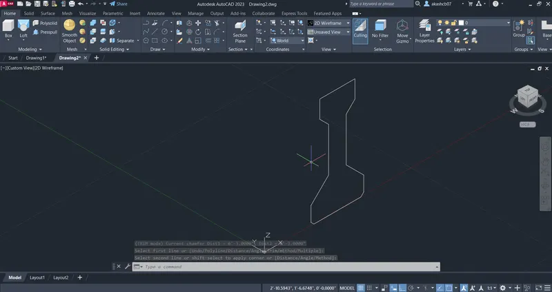
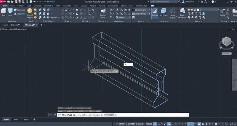
Result:
Q.4 Ans
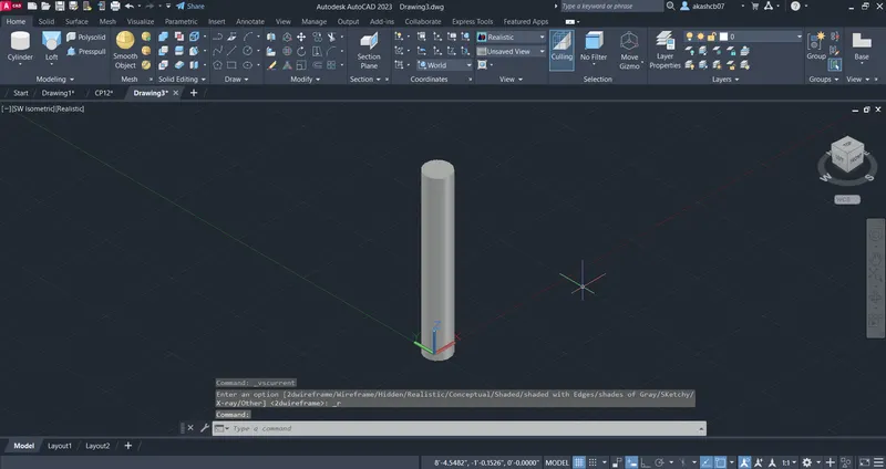
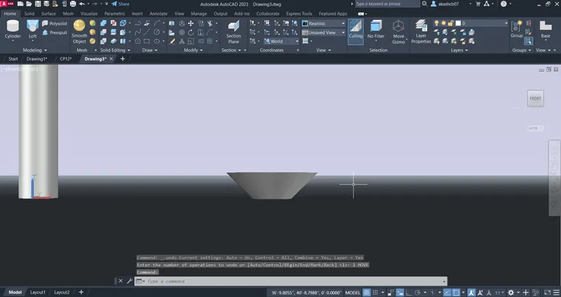
Aim: Create a 3D model of drop column.
Procedure:
Step 1:
- Open the new AutoCAD file with imperical unit to provide the dimension in feet and inches.
- We have to create a 3D model of Drop column so we have to change some setting for 3D.
- Go to Bottom toolbar -> Workspace -> Change the workspace from 2D drafting to 3D modeling. 3D interface will be open now.
- Create a front view of the Drop column by using the "polyline" tool.
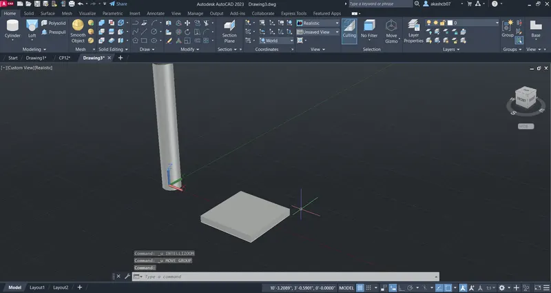
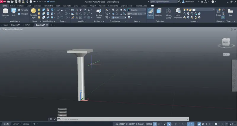
- Create a geometry of Drop column first we have to create a bottom portion of the cylinder.
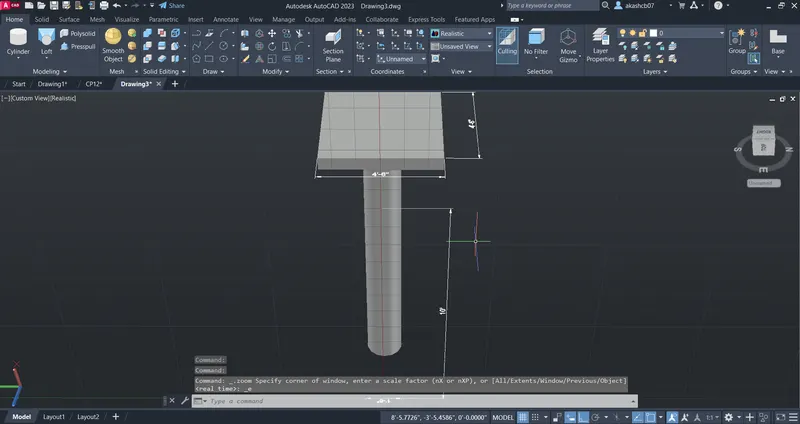
- Create a bottom portion of column which is cylinder which has a size of 1'6" in diameter and height of 10' as given.
- Create a Top portion and add it.
- Go to extrude command and the extrude the created boundary.
- Go to Annotate -> Dimension and use the linear dimension tool to provide dimension.
- Use UCS command to change the axis of the dimension.
- Go to -> Custom view and change the view as Realistic, conceptual,hidden,shaded etc.
Result:
Q.5 Ans
Aim: Create a 3D model of Wall.
Procedure:
Step 1:
- Open the new AutoCAD file with imperical unit to provide the dimension in feet and inches.
- We have to create a 3D model of Wall so we have to change some setting for 3D.
- Go to Bottom toolbar -> Workspace -> Change the workspace from 2D drafting to 3D modeling. 3D interface will be open now.
- Create a front view of the Wall by using the "polyline" tool.
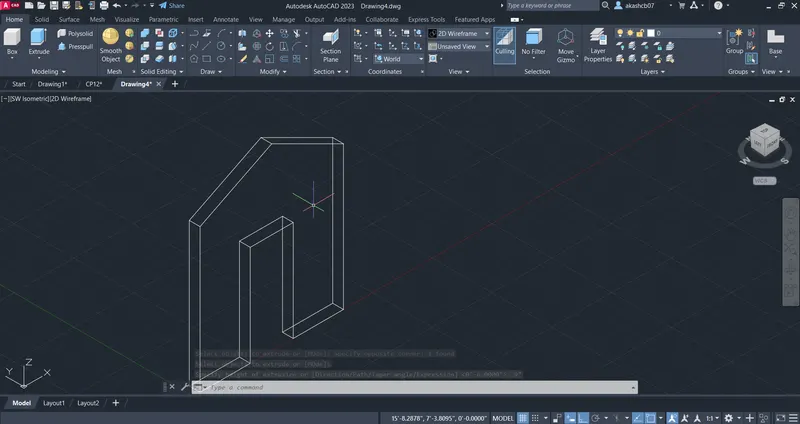
- Create a geometry of Wall first.
- Go to extrude command give the extrusion of 6" and the extrude the created boundary.
- Go to Annotate -> Dimension and use the linear dimension tool to provide dimension.
- Use UCS command to change the axis of the dimension.
- Go to -> Custom view and change the view as Realistic, conceptual,hidden,shaded etc.
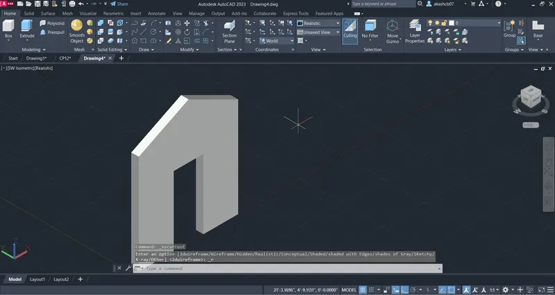
Result: